| |
|
|
Note:
Clicking on any picture or illustration will open a larger version
of that art.
|
|
Diesel
Fuel Additives |
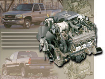
This information
pertains to 1994-2003 vehicles with 6.5L or 6.6L Diesel Engine (VINs
F, P, S, Y, 1 -- RPOs L65, L49, L56, L57, LB7). (fig. 1)
TIP: The use of diesel fuel additives is not required or recommended
for the 6.5L diesel or the 6.6L Duramax® Diesel engine under normal
conditions. The filtering system is designed to block water and contaminants
without the use of additives. However, some customers may desire to
use fuel additives to improve the characteristics of available diesel
fuels.
Water Emulsifiers and Demulsifiers
Fuel additives must be selected carefully. There are two common methods
that fuel additives use to cope with water in the fuel.
Demulsification causes water particles to combine together to form
larger particles, which drop out of suspension. This allows the fuel
filter/water separator to separate the water from the fuel as it is
designed to.
Emulsification keeps water particles suspended in the fuel. Alcohol
is frequently used as the emulsifier. Emulsification can allow water
to get past the fuel filter/water separator, in most cases causing
damage to the fuel system.
IMPORTANT: Only alcohol-free water demulsifiers should be used in General
Motors Diesel engines. Both Racor® and Stanadyne® diesel fuel
additives are alcohol-free and utilize water demulsifiers to cope with
water in the fuel. Other brands may be available in different areas.
Before using them, be sure they clearly state that they are alcohol-free
demulsifiers.
(We believe these sources and their products to be reliable. General
Motors does not endorse, indicate any preference for or assume any
responsibility for the products from this firm or for any such items,
which may be available from other sources.)
COMMON DIESEL FUEL CONCERNS
Fuel Waxing/Icing
Fuel distributors blend number 1 and number 2 diesel fuels for seasonal
requirements in a particular region. No other blending of fuels is
recommended. However, a customer may desire to use a winter fuel additive
to prevent fuel waxing or icing during extreme cold snaps. If a winter
fuel additive is used, it should not contain alcohol or other water
emulsifiers that may compromise the water removal effectiveness of
the fuel filtering system.
Bacteria and Fungi Growth
Bacteria and fungi growth can occur in diesel fuel when there is water
present, especially during warmer weather. The best prevention against
bacteria and fungi growth is to use clean fuel that is free of water.
There are diesel fuel biocides available to kill bacterial growth in
the fuel system. However, the dead bacteria can cause blockages throughout
the fuel system. If bacterial growth is found in the fuel system, the
proper method of removal is to flush the fuel system using service
manual procedures, replace the fuel filter element, and refill the
tank with clean diesel fuel. If a customer desires to use a biocide
after flushing the fuel system, it should not contain alcohol or other
water emulsifiers.
Low Cetane Number
The cetane number is one indicator of a diesel fuel's ability to ignite.
There are many indicators of overall fuel quality such as cleanliness,
specific gravity, volatility, viscosity, detergency, corrosion inhibiting
abilities, and lubricity. Increasing the cetane number alone is not
a fix for poor quality fuel. Additionally, increasing the cetane number
beyond the engine's requirements will not increase performance. However,
the cetane number of diesel fuel is not always consistent and some
customers may desire to use a cetane improver to ensure full performance
of their engine. If such an additive is to be used, it must not contain
alcohol or other water emulsifiers.
Poor Lubricity
The 6.5L diesel and the 6.6L Duramax® Diesel engines are designed
to operate on today's low sulfur fuel without the use of additives.
A fuel additive designed to increase lubricity is not a fix for poor
quality or contaminated fuel, but some customers may desire to use
a lubricity additive to aid in the longevity of their fuel system components.
If such an additive is to be used, it must not contain alcohol or other
water emulsifiers.
FUEL SOURCE ISSUES
If a vehicle is properly maintained but has fuel contamination issues,
consider obtaining fuel from a different source. Purchasing fuel from
a high volume fuel retailer increases the likelihood that the fuel
is fresh and of good quality.
-
Thanks to Andy Sutherland |
figure
1 |
|
|
|
|
|
|
| Tech 2 Replacement
-- Fact or Fiction? |
Did you hear the one about the
guy who bought the latest high-tech (you fill in the blank) and it was
obsolete before he opened the box?
Or version 7.0 of a hot computer game being released before version 6.0
went on sale?
So, naturally you’re skeptical about the life expectancy of the
Tech 2, right? Your shop could really use an additional one, but you
don’t want to buy something that’s going to be obsoleted
right away. What to do?
Designed for Expansion
When the Tech 2 came out in 1996, it had 10 times the mass storage capacity
of the Tech 1 it replaced, and four times the display space on the screen.
The processor went from 8 bits to 32 bits, so it was considerably faster.
That was then; this is now. Is the Tech 2 able to keep up?
To put your mind at ease, remember that the Tech 2 was designed to
be changeable and expandable, right from the start. This is evidenced
by
the fact that it contains two memory card slots. And the fact that
the 32 MB card was released in December 2001 to replace the previous
10 MB
card. With that one step alone, the Tech 2’s storage capacity
was tripled.
REMINDER: The 32 MB card is the primary card to be used. If you have
not already done so, remove the 10 MB card from your Tech 2. The 10 MB
card has been the source of some communication errors.
With the onset of GMLAN (TechLink, Mar. 2003), the CANdi module now enables
the Tech 2 to communicate with a whole new data protocol. Other such
communication modules may be developed in the future, to extend the useful
life of the Tech 2 even further.
Some of the components used in the manufacture of early Tech 2s are no
longer available. So, tool engineers have found ways of redesigning circuits
for later Tech 2s to use currently available components. These
Tech 2s work exactly as the original did. This extra development work was done
to ensure that the Tech 2 did not become obsolete, as parts supplies
changed.
This kind of refinement is costly, and would not be undertaken if the
Tech 2 were approaching the end of its life.
What’s Coming
Many of the operating features of the original Tech 2 resulted from surveys
of retail technicians. This is an ongoing process. At present, surveys
are being used to gain insight into where the handheld diagnostsic computer
needs to go in the future. Should it be a laptop? Or a PDA? Have wireless
capabilities? Have handwriting recognition?
At present, the Tech 2 replacement isn’t even in spec form yet.
There is a lot of research and development needed before anything like
a “Tech 3” becomes a reality. This won’t be soon, and
when it does happen, it won’t be a surprise. There will be plenty
of advance information and notice before a new tool becomes essential.
Diagnostic tools can have a very long lifespan. In fact, the Tech 1 is
still being sold after 13 years!
Diagnostic technology certainly doesn’t stand still. There’s
always a need and a desire to diagnose it faster and display it better.
Research and development are ongoing. But a significant milestone such
as a Tech 2 replacement is not on the horizon.
What Should You Do?
Remember, the Tech 2 isn’t going to be replaced until a vehicle
operating system comes along that the Tech 2 can’t be made to
talk to. This is not in the foreseeable future.
So, if you need an additional Tech 2, you can purchase it with confidence
that it will remain useful and current for a long time to come. Contact
GM Dealer Equipment at 1.800.GMTOOLS (1.800.468.6657).
-
Thanks to Mark Palmer, John Cicala, Jeff Flood and Mark Stesney |
| |
|
Know-How
Broadcasts for May |
| |
 |
| Know-How
Broadcasts for May |
|
Emerging
Issues
|
May
13, 2003
|
9:00
AM, 12:30 PM,
3:30 PM
Eastern Time
|
|
10270.17D
-- 2004 Chevrolet Passenger Cars New Model Features
|
May
29, 2003
|
9:00
AM, 12:30 PM,
3:30 PM
Eastern Time
|
| -
Thanks to Tracy Timmerman |
|
|
|
|
|
Brake
Pipe Flaring Tool
|
GM
has begun installing vinyl-coated double wall brake pipes on some vehicles.
This will eventually spread to other vehicle lines.
The black coating offers additional protection to the metal pipe. However,
it interferes with the flaring process, so it must be stripped from pipes
before flaring can be done.
Some pre-formed brake pipes are available for service replacement. Others
must be fabricated from bulk pipe. If you must fabricate a pipe, or repair
a pipe on a vehicle, you will have to form flares on the ends of the
pipes.
TIP: When installing any brake pipe to the vehicle, be sure to torque
the nuts to the proper specification. Refer to the appropriate SI section
for details.
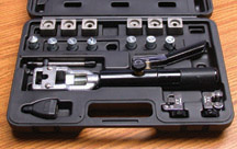
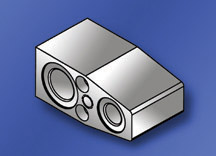
The Brake Pipe Flaring Set J-45505 contains all of the tools necessary
to cut, strip and flare brake pipe (fig. 2). These tools have been made
as small as practical, to permit them to be used in cramped areas on
the vehicle.
TIP: This flaring set will work with non-coated brake pipes as well.
Refer to the photographs. Instructions are included on a label attached
to the lid of the storage case.
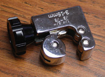
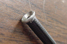
The brake pipe cutter can be adjusted to cut tubing from 1/8-inch to
5/8-inch (3 - 16 mm). (fig. 3)
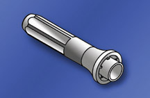
The stripper is equipped with two guide rollers and an adjustable stripping
blade (fig. 4). Simply insert the pipe between the rollers until it contacts
the stop. This controls the length of coating that is removed. Then snug
the rollers and twist the stripper to remove the vinyl coating (fig.
5).
After cutting, it’s necessary to use the deburring tool to remove
burrs from both the inside and outside of the cut end of the pipe.
Select the appropriate die set and install into the hydraulic hand pump.
Install the proper nut on the pipe. Then insert the pipe into the die
and operate the handle. The hydraulic ram creates the properly shaped
flare with minimal effort.
TIP: Be sure to use the proper die type. Past and present GM vehicles
use either single lap (fig. 6) or double lap flares (fig.
7). Using the
incorrect type can lead to brake system failure.
- Thanks to Rich Staton, Stabilus |
figure
2 |
figure
3 |
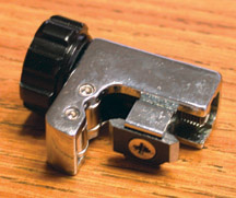 figure 4
 |

figure
5 |

figure
6 |
figure
7 |
| return
to Table of Contents |
| |
| Fuel
Level Sensor |
This
information applies to 2000-2003 Cavalier, Sunfire, Malibu, Alero and
Grand Am with an inaccurate fuel gauge level reading.
If normal diagnostics lead you to replace the fuel level sensor, here
is some late-breaking news.
A new fuel level sensor is manufactured with gold contact surfaces to
provide protection against sulfur and contamination in the fuel.
TIP: The previous sensor/pump module is no longer available.The fuel
level sensor and the fuel pump module are available as separate replacement
parts.
TIP: If you are dealing with an inaccurate gauge condition, install the
sensor. If you are dealing with a fuel system performance condition,
install the fuel pump module.
Details will be given in an upcoming bulletin.
-
Thanks to Steve Oakley
Fuel Level Sensor 22709333 |
Fuel Pump Module (excludes sensor) 88957239 |
|
| |
| |
| return
to Table of Contents |
|
| Blue
Fog Lamps |
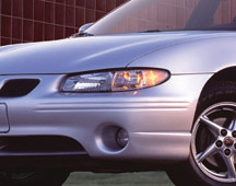
The
2003 Limited Edition Grand Prix has special blue fog lamps. The replacement
bulb is different from current Grand Prix lamps (fig.
8). The replacement
bulb has a wire pigtail and is available from GMSPO under AC Delco
part number 11513798.
TIP: It is not necessary to replace the entire fog lamp when the lamp
burns out. Replace only the bulb.
-
Thanks to Fred Tebbets |
figure
8 |
| return
to Table of Contents |
|
| Instrument
Panel Top Pad Gap |
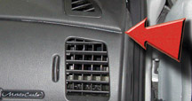
On
2002-03 Impala and Monte Carlo, a gap condition may exist between
the Upper I/P pad to I/P trim plate, which may be objectionable to
a customer (fig.9).
It is possible to correct or improve the appearance of the Upper I/P
pad without replacement. Loosen the attachment screws at or near the
area of the gap and retighten while firmly holding the Upper I/P Pad
down, closing the area of the gap. Repositioning the I/P Upper Pad in
this fashion should eliminate the gap, without requiring the replacement
of the I/P Pad.
-
Thanks to Gary McAdam |
figure
9 |
| |
| |
| return
to Table of Contents |
|
| OnStar
Wake Up Cycle Change |
To create a more streamlined OnStar enrollment process, the vehicle
assembly centers are making a change to the OnStar module wake up
cycle. These will occur according to the schedule in the accompanying
tables.
Remember, in order for OnStar to perform remote functions while the vehicle
is off (door unlock, alerts, theft tracking, etc.) the OnStar module
must wake up at specified intervals and ready itself to receive a call
from the OnStar call center. This wake up cycle is commonly referred
to as DRx (Discontinuous Receive).
Previously, unconfigured OnStar equipped vehicles did not perform this
wake up cycle; the module was always asleep with the ignition off. The
wake up cycle started only after the OnStar system was configured.
Beginning in January of 2003, the following change is being made. Unconfigured
vehicles will wake up every 10 minutes for a period of approximately
1 minute. This wake up cycle starts after each ignition cycle, and ends
after 24 hours. The OnStar module will then return to sleep mode until
the ignition is cycled again. Once the vehicle is configured, the module
will return to the traditional wake up cycle. The vehicle will wake up
1 minute out of every 10 minutes over a 48 hour period following an ignition
cycle.
TIP: Be aware of this change when performing battery parasitic drain
diagnosis.
TIP: The OnStar module can be shut down using the Class 2 Message Monitor
of the Tech 2. This does not affect the DRx cycle; the OnStar module
will still wake up at the scheduled time.
- Thanks to Dale Tripp and Mike Batchik
Models
With Modified Wake-up Cycle beginning Jan. 31, 2003 |
2003 Hummer H2
2003 Saturn ION
2003 Bonneville
2003 Aurora (V8)
2003 Cavalier
2003 Montana
2003 Sunfire
2003 Silhouette
2003 Aztek
2003 Venture
2003 Rendezvous |
2003 LeSabre
2003 Cadillac CTS
2003 Saturn VUE*
2003 Saturn LS/LW*
2003 Monte Carlo*
2003 Impala*
2003 Cadillac DeVille*
2003 Cadillac Seville*
2004 Cadillac SRX*
2004 Cadillac XLR
2004 Grand Prix |
| * Vehicles will be transitioning from Gen 4 OnStar
to Gen 5 OnStar sometime after Jan 31, 2003. The wake up cycle
modification will occur concurrent with this change. |
Models with modified Wake-up Cycle Estimated Dates |
GMC
Savana and Chevrolet Express
Envoy XL, Envoy XUV, Trailblazer EXT
Full-Size Truck (less H2)
Trailblazer, Envoy, Bravada |
Feb.
2003
Feb. 2003
Mar. 2003
Mar. 2003 |
|
| |
| |
|
return
to Table of Contents |
|
| Recent
Essential Tool Shipments |
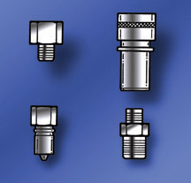
Several
essential tools were shipped to dealers recently.
J-34730-40 Fuel Pressure Gauge Quick Connect Adapters (fig.
10)
Hummer H1
These adapters are used with the J-29658-D Fuel Pressure Gauge kit and
J-34730-1A Fuel Pressure Gauge and Hose Assembly to test and diagnose
the supply and return fuel systems.
J-45268-115 TXV Adapter (fig. 11)
2004 Grand Prix, Impala, Monte Carlo, SLR, Malibu, Corvette
This adapter is used to replace the TXV when doing an A/C flush with
the ACR2000. The TXV must be removed to allow refrigerant to flow through
the A/C system.
J-46405 Seal Installer (fig. 12)
1997-Current Corvette, XLR
The axle shaft seal has been updated for improved performance. The J-36797
Seal Installer no longer fits. The new installer fits both the new seal
and the first design seal.
- Thanks to Ryan Jankowski |
| 
figure
10
|
figure
11 |
figure
12
|
| return
to Table of Contents |
|
| Increased
Steering Effort |
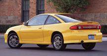
This
condition affects 2003 Chevrolet Cavalier (fig.
13), Pontiac Sunfire,
Grand Am, and Oldsmobile Alero equipped with 2.0 Litre L61 EcoTech
engine (VIN Code F).
A customer may comment on increased steering effort at vehicle start
up on mornings with low ambient temperatures (below 30° F, -2°C).
It may be difficult to confirm this condition, as it may be somewhat
intermittent. Normal testing of the steering system (flow meter, test
drive, etc.) after vehicle warm up may also be inconclusive. The cause
of this condition is a priming issue with the power steering pump. The
problem is not within the steering rack. The correct repair procedure
is to replace the power steering pump.
Delphi Engineering is currently taking steps to identify and resolve
this issue.
- Thanks to Steve Oakley |
|
figure
13 |
| return
to Table of Contents |
|
| Air
Suspension Diagnostic Code |
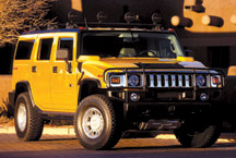
This
condition may occur on a 2003 Hummer H2 (fig.14) with Electronically
Controlled Air Suspension (ECAS).
While using a Tech 2, if you should encounter a DTC 0660 stored in
history, simply delete the code. This can occur upon a rapid ignition
cycle from ‘accessory’ to ‘crank,’ while
the ECU is performing a self test. A ‘green’ engine causes
a significant voltage drop during initial crank. There is no effect
on the function of the air suspension and will not be cause for concern
for a customer.
TIP: The code will disappear on its own after 100 key cycles and should
not reset.
-
Thanks to Terry Nicholas |
figure
14 |
|
return
to Table of Contents |
|
| Delphi
P04 PCM |
The
Delphi P04 Powertrain Control Module (PCM) may set both 5-volt reference
DTCs simultaneously during a specific failure condition. Depending
on the vehicle platform, these are DTCs P1635/1639 or P0641/0651.
The failure condition resulting in both 5-volt reference codes being
set occurs when the Intake Air Temperature (IAT) sensor signal circuit
is shorted to battery voltage during start-up. The most likely failure
will be an IAT sensor signal circuit that is shorted to a switched ignition
voltage circuit. When the PCM circuitry is exposed to this high voltage,
a miscalculation may occur in the analog-to-digital (A/D) counts, used
in the PCM software. If this miscalculation exceeds a calibrated threshold,
the PCM may set both P1635/1639 or P0641/0651.
To correct this condition, test the IAT sensor signal circuit for a short
to voltage and repair as necessary. Be sure to verify that the IAT sensor
itself has not been damaged. Correct and repair any other DTCs or faults
that may be present. There has not been any reported damage to PCMs as
a result of this failure.
Use the table to determine which vehicle platform/engine combinations
are using the P04 PCM:
-
Thanks to Jim Hanna
|
1998 |
1999 |
2000 |
2001 |
2002 |
2003 |
Park
Avenue |
3.8L |
3.8L |
3.8L |
3.8L |
3.8L |
3.8L |
LeSabre |
3.8L |
3.8L |
3.8L |
3.8L |
3.8L |
3.8L |
Firebird |
3.8L |
3.8L |
3.8L |
3.8L |
3.8L |
3.8L |
Camaro |
3.8L |
3.8L |
3.8L |
3.8L |
3.8L |
3.8L |
Impala |
–– |
–– |
|
3.4
/ 3.8L |
3.4
/ 3.8L |
|
Monte
Carlo |
3.1
/ 3.8L |
3.1
/ 3.8L |
3.4
/ 3.8L |
3.4
/ 3.8L |
3.4
/ 3.8L |
3.4
/ 3.8L |
Lumina |
3.1
/ 3.8L |
3.1
/ 3.8L |
3.1L |
3.1L |
3.1L |
3.1L |
Grand
Prix |
3.1
/ 3.8L |
3.1
/ 3.8L |
3.1
/ 3.8L |
3.1
/ 3.8L |
3.1
/ 3.8L |
3.1
/ 3.8L |
Grand
Am |
3.1L |
3.4L |
3.4L |
3.4L |
3.4L |
3.4L |
Bonneville |
3.8L |
3.8L |
3.8L |
3.8L |
3.8L |
3.8L |
Alero |
– |
3.4L |
3.4L |
3.4L |
3.4L |
3.4L |
Malibu |
3.1L |
3.1L |
3.1L |
3.1L |
3.1L |
3.1L |
Regal |
3.8L |
3.8L |
3.8L |
3.8L |
3.8L |
3.8L |
Century |
3.1L |
3.1L |
3.1L |
3.1L |
3.1L |
3.1L |
Venture |
3.4L |
3.4L |
3.4L |
3.4L |
3.4L |
3.4L |
Silhouette |
3.4L |
3.4L |
3.4L |
3.4L |
3.4L |
3.4L |
Transport |
3.4L |
3.4L |
– |
– |
– |
– |
Montana |
– |
– |
3.4L |
3.4L |
3.4L |
3.4L |
Eighty-Eight/LSS |
3.8L |
3.8L |
– |
– |
– |
– |
Riviera |
3.8L |
3.8L |
– |
– |
– |
– |
Intrigue |
3.8L |
3.5
/ 3.8L |
3.5L |
3.5L |
– |
– |
Rendezvous |
– |
– |
– |
– |
3.4L |
3.4L |
Aztek |
– |
– |
– |
3.4L |
3.4L |
3.4L |
Achieva |
3.1L |
– |
– |
– |
– |
– |
Cutlass |
3.1L |
3.1L |
– |
– |
– |
– |
Skylark |
3.1L |
– |
– |
– |
– |
– |
|
| |
| |
| return
to Table of Contents |
|
| Chemical
Damage To Polycarbonate Headlamp Lenses |
This
information applies to 2003 and prior passenger cars and trucks and
2003 Hummer H2. Refer to bulletin 02-08-42-001.
Most late model vehicles have polycarbonate headlamp lenses. This material
is used because of its temperature and high impact resistance.
A variety of chemicals can cause crazing or cracking of the headlamp
lens. Headlamp lenses are very sensitive. Exercise care to avoid contact
with all exterior headlamp lenses when treating a vehicle with any type
of chemical, such as those recommended for rail dust removal. Rubbing
compound and cleaner waxes may also attribute to this condition. This
could result in the need to replace the entire headlamp housing.
Also, crazing or deformations of the lens may occur if a shop mat or
fender cover is draped over the fender and covers a portion or all of
the headlamp assembly while the DLR or headlamps are on. This action
restricts the amount of heat dissipated by the headlamps.
Once heat buildup is generated by the headlamp, a degradation of the
headlamp lens begins. This degradation of the lens can be unnoticeable
at first and eventually show up as spider cracks. In more extreme cases,
it will begin to melt the lens of the headlamp.
-
Thanks to Bob Broughton and Katie Callahan |
| |
| |
| return
to Table of Contents |
|
| Splice
Corrosion |
Owners
of some 2003 Pontiac Sunfires may comment that the left headlamp is
dim, the high beam indicator is on, and the SVS lamp may be illuminated.
The Tech 2 scan tool may reveal a code B2601. Some customers may also
comment on the left or right fog lamp appearing dim or not illuminating.
The forward electrical harness has splices that may be inadequately sealed
from corrosive elements. Road splash, especially during winter months
may force water into the harness causing increased resistance and eventual
separation of the splices.
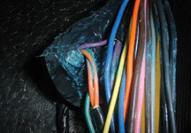
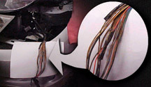
Locating the Affected Splices
TIP: You may be able to locate the affected splices visually before removing
the electrical tape wrap. A green mark or spot may have leeched out through
the tape leaving a visual indicator of where to begin removing the tape
(fig. 15). Carefully cut and remove the electrical tape wrapping the
wire harness.
In the case of dim high beam, investigate splice 107 (pink) and splice
108 (dark blue) for corrosion (fig. 16). These splices are located next
to the windshield wiper reservoir and are associated with circuit 593.
High resistance in these splices can cause the driver side headlamp to
dim.
TIP: Splice number 118 (light blue) is located in very close proximity
to the other splices, and is protected in the same manner. This splice
involves the left front turn signal circuit on the vehicle. It is recommended
that it be repaired and protected at the same time.
In the case of dim fog lamps, investigate splice 213 (purple) and splice
113 (orange).
IMPORTANT: In the same area as the orange and purple splices but more
toward the driver’s side, you will find a black wire splice. Inspect
this splice for signs of corrosion. Do not cut into or in any way disturb
this splice unless you see visual signs of corrosion. If evidence of
corrosion is found, re-splice the connection in the same manner as the
other wires.
Repair Procedure
Strip back the wires until clean non-corroded wire is available.
Resplice the wires, using GM crinp and seal connectors P/N 12089189 only.
These connectors are equipped with an internally knurled crimp joint
and heat shrink tubes.
Insert the bare wires fully into the body of the connector. Using the
J-38125-8 crimping tool, fully crimp the body of the connector.
Using the J-38125-5 Ultra Torch from your J-38125-C Terminal Repair Kit,
progressively heat the connector by waving the torch quickly over both
the plastic shrink tube (to activate it) and body of the connector to
get the internal sealant to flow.
Cut a 3M® Electrical Moisture Sealant Patch in half. Apply the patch
to the splice as indicated on the package.
Refer to an upcoming bulletin for further details.
-
Thanks to Steve Oakley |
figure
15 |
figure
16 |
| |
| return
to Table of Contents |
|
| Neutral
Start Backup Switch |
Some
2001-2003 Sierra and Silverado trucks equipped with Allison Series
1000 Automatic Transmission (M74) may have multiple DTCs including
any or all of the following: P0708, P0847, P0872, P0875, P1711, P1713;
partial or no PRNDL display; and no movement.
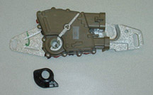
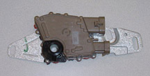
This condition may be caused by water contamination and corrosion inside
the NSBU (Neutral Start Backup switch) located on the side of the transmission.
Install a new NSBU, P/N 29540479 that has better sealing to resist internal
corrosion (fig. 17). Replacement procedures can be found in SI document
652003. Adjustment procedures can be found in SI document 652060.
When replacing this switch, observe these important points.
First, if the NSBU does not easily slide off the selector shaft, use
a file to remove any burrs or raised metal where the selector lever seats
against the shoulder of the shaft. If the new NSBU is forced over this
raised metal, it may fit the shaft loosely, causing possible repeat DTCs.
Second, be sure to install the splash shield that is included with the
NSBU kit (fig. 18). This shield is installed over the manual shaft before
the shift lever and nut are installed. Failure to install this shield
may result in repeat switch contamination.
Finally, before starting the vehicle, be sure to clear all DTCs.
-
Thanks to Mark Gordon
|
figure
17 |
figure
18 |
| return
to Table of Contents |
|
| Exhaust
Boom or Vibration |
Vehicles
with the 4.2L L6 engine may exhibit a boom or vibration coming from
the exhaust, at or near idle.
The following may help reduce the vibration. Unbolt the downpipe from
the exhaust manifold outlet and replace the donut seal. When you tighten
the downpipe to the manifold, have a second technician hold the rear
end of the downpipe so the two exhaust hangers stay centered in the rubber
bushing holes. Keeping the rods centered in the bushing holes makes a
noticeable improvement.
-
Thanks to GM Technical Assistance |
| |
| return
to Table of Contents |
|
| Vehicle
Customization or Personalization Inoperative |
On
2003 Buick Rendezvous and Pontiac Aztek, the Body Control Module (BCM)
was revised to accommodate vehicle system changes. Because of memory
capacity, on vehicles without Driver Information Center (DIC), certain
customization options had to be deleted.
Vehicles with DIC retained customization of some features controlled
by the BCM, depending on vehicle options.
These decisions were made after final editing of Owner’s Manuals
and Service Manuals, so the Owner’s Manual contains customization
information pertaining to earlier models.
Service replacement BCMs contain the revised programming and supercede
previous BCM part numbers.
IMPORTANT: If the original BCM is
replaced in past model year vehicles, previously available customization
features
will be lost.
-
Thanks to GM Technical Assistance
|
| return
to Table of Contents |
|
| Bulletins – MARCH,
2003
This review
of service bulletins released through mid-March lists the bulletin
number, superseded bulletin number (if applicable), subject and models. |
00 – General
Information
03-00-89-001; Paint Code Corrections; 2003 Chevrolet Suburban, Tahoe,
GMC Yukon, XL
03-00-89-002; New Owner Orientation Clinic Materials Now Available Online;
2003 and Prior Passenger Cars, Trucks, Hummer H2
03-00-89-003; GM Goodwrench Limited Lifetime Service Guarantee; 2003
and Prior Passenger Cars, LD Trucks and Hummer H2
02 – Steering
00-02-35-003B; replaces 00-02-35-003; Clunking Noise Under Hood and Can
Be Felt in Steering Wheel (Lubricate Intermediate Steering Shaft Assembly);
specified 1999-2003 Chevrolet, GMC, Cadillac and Hummer H2 Vehicles with
Recirculating Ball Steering
03-02-35-001; Noise/Clunk from Steering Column (Replace Upper Intermediate
Shaft); 2003 Cadillac CTS
03-02-35-002; Minor Scratches to Wood Stering Wheels (Refinish); 2000-03
Cadillac DeVille, Escalade, Seville, CTS with Wood Steering Wheels
03 – Suspension
99-03-10-009A; replaces 99-03-10-009; Wheel Balance Weight Usage; specified
1999-2003 Chevrolet, GMC, Cadillac and Hummer H2 Vehicles
03-03-09-001; Rear of Vehicle Appears to Sit Low, Low D Trim Height Measurement
(Replace Rear Coil Springs); 2003 Chevrolet Tahoe with Off-Road Chassis
Package (RPO Z71), 3rd Row Seat (RPO AS3), and Off-Road Appearance Package
(RPO BHP)
03-03-10-002; Use of Correct Installation Procedure for Loose Hubcab
Assembly; specified 1998-2003 Chevrolet and GMC Trucks
04 – Driveline Axle
03-04-17-001; Whine Noise from Rear Axle (Diagnose and Replace Rear Shaft
with a Tuned Torsional Damper Rear Propeller Shaft); 2002-03 Cadillac
Escalade EXT, Chevrolet Suburban, Avalanche, GMC Yukon XL, Denali
03-04-20-001; Revised Rear Axle Assemble Procedure and Special Tools;
1997-2003 Chevrolet Corvette
03-04-20-002; Revised Output Shaft Seal Replacement Procedure; 1997-2003
Chevrolet Corvette
05 – Brakes
02-05-26-002A; replaces 02-05-26-002; Scraping Noise from Rear of Vehicle
(Replace Parking Brake Shoe Kit and Clean Drum in Hat Rotor); specified
1999-2003 Cadillac, Chevrolet and GMC Trucks
03-05-23-001; Brake Pulsation/Vibration, Contamination/Corrosion Between
Hub and Rotor and/or Drum and Axle Flange (Clean Rotor and Hub and/or
Drum and Axle Flange Mounting Surface), 1999-2003 Chevrolet Tracker
06 – Engine/Propulsion System
99-06-01-012A; replaces 99-06-01-012; Remanufactured Supercharger Replacement
Units; specified 1992-2003 Vehicles with 3.8L Supercharged V6 Engine
(NIV 1 -- RPO L67)
01-06-01-010B; replaces 01-06-01-010A; Polymer Service Pistons; specified
1996-99 Vehicles with 3.1L Engine (NIV M -- RPO L82)
02-06-03-001; Starter Cranks After Key is Released on Cold Start (Normal
Condition); 2003 Chevrolet Silverado, Suburban, Tahoe, GMC Sierra, Yukon,
XL with 5.3L Engine (NIV Z -- RPO L59)
02-06-04-010; 6.6L LB7 Duramax Diesel Fuel Pressure Regulator Replacement;
2001-03 Chevrolet Silverado, GMC Sierra 2500/3500, Chevrolet Kodiak,
GMC Topkick C4500/C5500 with 6.6L Duramax Diesel Engine (NIV 1 -- RPO
LB7)
02-06-04-054A; replaces 02-06-04-054; Increased Accelerator Pedal Effort
(Clean Throttle Body and Adjust Blade); 1999-2002 Chevrolet Silverado,
Suburban, Tahoe, Avalanche, GMC Sierra, Yukon, XL with 4.8L or 5.3L V8
Engine (NIVs V, T, Z -- RPOs LR4, LM7, L59)
03-06-01-002; New Polymer Coated Piston and Rod Assembly; specified 1997-2003
Vehicles with 3.1L or 3.4L V6 Engine (NIVs E, J -- RPOs LA1, LG8)
03-06-01-003; Flywheel/Flexplate Replacement; 2003 Passenger Cars and
LD Trucks
03-06-04-011; Programming/Re-Programming, Setup, Configuration of Modules
(TBCM, BCM, PCM, VTD, Radio, IPC, DTCs) 2002 Chevrolet TrailBlazer, EXT,
GMC Envoy, XL, Oldsmobile Bravada
03-06-04-012; Inspection of All Related Wiring Hrness Connections When
Diagnosing Miscellaneous DTCs, Intermittent Driveability Concerns, Hard
Start, No Start, Incorrect Gauges, Inoperative A/C Systems, SES Lamp
Illuminated, 4WD Lamp Illuminated, IP Gauges Inoperative, Cruise Inoperative;
2003 and Prior Cars, LD Trucks, Hummer H2
03-06-04-013; SES/CEL and/or ABS Warning Light Illuminated, Erratic Speedomter
and/or Erratic Shifting, Multiple DTCs set (Reposition Surge Tank Hose
Clamp and Repair Wires); 2003 Cadillac DeVille
03-06-05-003; Rattle or Buzz Type Noise from Exhaust System (Install
Clamp); 2001-03 Buick Rendezvous, Chevrolet Venture, Oldsmobile Silhouette,
Pontiac Aztek, Montana with FWD only
07 – Transmission/Transaxle
99-07-30-017A; replaces 99-07-30-017; Automatic Transmission Oil Cooler
Flushing and Flow Check Procedures; 2003 and Prior LD Trucks and Hummer
H2
02-07-30-029B; replaces 02-07-30-029A; Powertrain Quality Center for
Engine and Transmission Assembly and Transfer Case Replacement; 2003
and Prior Passenger Cars, LD Trucks, Hummer H2
03-07-30-001; Transmission Slipping or Torque Converter Clutch (TCC)
Inoperative with No SES Light Displayed and No DTC P1870 (Reprogram PCM
and Diagnose Vehicle Using P1870 Diagnostic Table); 2003 Chevrolet TrailBlazer,
EXT, GMC Envoy, XL, Oldsmobile Bravada
02-07-30-012B; replaces 02-07-30-012A; Hydra-matic 5L40-E Serviceable
Components and Labor Operations; 2003 Cadillac CTS with 2.6L or 3.2L
Engine (NIVs M, N -- RPOs LY9, LA3)
02-07-30-052B; replaces 02-07-30-052A; Automatic Transmission Oil Cooler
Flush and Flow Test Essential Tool J-45096 TransFlow; 2003 and Prior
Passenger Cars and LD Trucks with Automatic Transmission, Hummer H2
03-07-31-001; Low Clutch Pedal Reserve, Poor Clutch Pedal Feel, Transmission
Difficult to Shift (Inspect Clutch Cable and Install Clutch Cable Retention
Block); 2003 Chevrolet Kodiak, GMC Topkick with Manual Transmission
03-07-30-002; Transmission Cooling System Service Tool J-45096, TrnasFlow
Information; 2003 and Prior Passenger Cars and LD Trucks with Automatic Transmission,
Hummer H2
08 – Body and Accessories
99-08-64-016A; replaces 99-08-64-016; Use of Silicone for Weatherstrip
Maintenance; 2003 and Prior Passenger Cars and Trucks, Hummer H2
01-08-51-004A; replaces 01-08-51-004; Premature Aluminum Hood Corrosion/Blistering
(Refinish); specified 1999-2003 Buick, Chevrolet, Oldsmobile, Pontiac
models
01-08-64-012C; replaces 01-08-64-012B; Door Glass Sash Out of Run Channel
(Repair Door Glass Sash Channel); 1999-2003 Oldsmobile Alero, Pontiac
Grand Am
01-08-64-018B; replaces 01-08-64-018A; Front Door Window Glass Won’t
Roll Up or Out of Channel (Replace Guide); 1999-2003 Oldsmobile Alero,
Pontiac Grand Am
02-08-44-020A; replaces 02-08-44-020; No Audio Out of Speakers at Times
(Reprogram Radio and/or Replace Amplifier); 2003 Cadillac Escalade, EXT,
Chevrolet Avalanche, Express, Silverado, Suburban, Tahoe, GMC Savana,
Sierra, Yukon, XL, Hummer H2
03-08-42-001; Dome Lamp Replacement Procedure; 2003 Cadillac CTS
03-08-44-002; Radio and/or HVAC Systems Change While DriNIVg (Reprogram
Driver’s Door Module); 2002 Chevrolet TrailBlazer, EXT, GMC Envoy,
XL, Oldsmobile Bravada
03-08-44-003; Revised Radio Poor Reception Diagnostic Information; 2002
GMC Envoy, Oldsmobile Bravada with RPO U84
03-08-46-001; Information Required by Technical Assistance Center from
Dealers Caling with ONStar and/or XM Radio Concerns; 2000-03 Passenger
Cars and Trucks, Hummer H2
02-08-46-010B; replaces 02-08-46-010A; Programming OnStar Module for
Canadian French Voice Recognition; specified 2003 Vehicles with OnStar
03-08-49-002; I/P Cluster Lens May Craze or Crack (Replace I/P Cluster
Lens Only); 2003 Chevrolet Cavalier
03-08-50-003; Seat Heater and/or Memory Power Seat Inoperative (Replace
Memory Seat Control Module); 2003 Cadillac Escalade, ESV, EXT, Chevrolet
Avalanche, Silverado, Suburban, Tahoe, GMC Sierra, Yukon, XL, Denali,
Denali XL, Hummer H2
03-08-50-004; Power Seat Switch Bezel Pops Out, Trim Comes Off (Install
Retainer to Bezel); 2002 Buick Park Avenue, Ultra
03-08-56-001; Shock Sensor Elimination; 1999-2000 Cadillac Escalade,
GMC Yukon Denali
03-08-64-002; Door Locks and/or Power Windows Inoperative (Re-route Wires);
2001-03 Chevrolet Tracker
03-08-64-003; Outside Rearview Mirror Shake or Vibration (Replace Outside
Rearview Mirrors); 1996-2002 Chevrolet Express Van, GMC Savana Van
03-08-66-002; Wind Noise Heard from Rear of Vehicle (Adjust Primary Seal
Flange); 1999-2003 Oldsmobile Alero, Pontiac Grand Am
03-08-66-003; Deck Lid Pull Down Effort too High (Replace Deck Lid Supports);
2003 Cadillac CTS
03-08-67-001; Proper Positioning of Roof Luggage Carrier Crossrails to
Avoid Windnoise; 2002-03 Chevrolet S-10 and GMC Sonoma Crew Cab Pickup
with Sport Appearance Package (RPO ZR5)
|
| return
to Table of Contents |
|
|
| |
|
|
|
| |
|
|
|
| |
|
|
|
|
