| |
|
|
Note:
Clicking on any picture or illustration will open a larger version
of that art.
|
|
Attention
Chevrolet Dealers |
Within the next
few weeks, the 2004 Chevrolet Malibu will begin to ship to dealers
(fig 1). This revolutionary new automobile joins the Cadillac XLR
and Saturn Ion in using the GMLAN (local area network) data communication
system1.
TIP: You can review GMLAN principles and purposes in the March 2003
TechLink.
TIP: You can learn more about the GMLAN system in rebroadcasts of the
Know-How 10270.15D – Tech 2 Functional Diagnostics & GMLAN.
The Malibu will use the GMLAN for everything but the ECM, which is
Class 2.
TIP: The Cadillac XLR uses the GMLAN primarily in the powertrain and
brake systems, while a Class 2 data system is used for body and accessory
controllers.
TIP: The 2004 Cadillac SRX uses GMLAN for the ECM and TCM on both 8
cylinder (LH2) and 6 cylinder (LY7) engines. The remaining modules
on the vehicle are on the Class 2 bus.
Your Tech 2 will require an interface called the CANdi module, to communicate
with the GMLAN. CANdi stands for controller area network diagnostic
interface. The CANdi modules and instructions for use will begin arriving
at Chevrolet dealerships shortly.
TIP: It’s strongly recommended that you perform the Tech 2 functionality
test before you connect the CANdi module.
In preparation for this new Tech 2 use, you must perform a functionality
test on your Tech 2 to be sure the circuits used by the CANdi module
are operating properly.
TIP: An explanation of the functionality test is being sent to Chevrolet
and Cadillac dealers along with this August issue of TechLink.
The software necessary to perform these tests should be available the
last week of August (Tech 2 software version 23.005). You must have
this enhanced software loaded to ensure accurate test results.
To perform the functionality test, you will need:
- Tech 2
- Tech 2 cable
- ALDL loopback adapter
- VCI
The instructions will guide you to perform the following routines built
into your Tech 2:
- VCI Automated Test
- VCI Dual Uart Test
- VCI TPU Option F6 Test
- VCI J1708 Test
These routines verify that a Tech 2 and VCI are working according to
specifications and able to work with the CANdi module. These tests
can also be found on your Tech 2 User Guide CD.
You can perform the functionality test quickly. Do it right away. This
will allow sufficient time if your Tech 2 needs repair.
TIP: The August 2002 issue of TechLink contained a thorough explanation
of how to obtain repair for the Tech 2, whether or not it is in warranty
or under a service contract. Guidance is available at the Techline
Customer Support Center (1.800.828.6860 English or 1.800.502.3222 French).
IMPORTANT: Cadillac dealerships received their CANdi modules in March,
along with instructions for the functionality test.
Copies of the functionality test are being sent again to Cadillac dealers
this month as a reminder.
TIP: If you haven’t run the test yet, do so immediately.
-
Thanks to Mark Stesney, Matt Singer, Craig Jones and Richard
St. Pierre |

figure
1 |
|
|
|
|
|
|
| Fuel
System Diagnostic Tips |
Part
I
Recent TechLink articles have covered:
- Changes in Gen III Engine Fuel Injection System (Jan. 2002)
- MFI Systems (Oct. 2002)
- Testing Fuel Injectors – Misfires (Dec. 2002)
- 3 Step Maintenance Fuel Induction Service Kit (Dec. 2002)
With many of the individual components addressed, it’s time to
examine the operation of the entire fuel system and how the components
interact.
Fuel injected engines require fuel under pressure to ensure correct fuel
delivery from the fuel injectors and to maintain driveability.
TIP: Proper fuel system diagnosis requires a fuel pressure gauge that
reads psi and kPa on a scale that is easy to see. Fuel pressure specifications
vary between platforms and engines. Always refer to SI for the current
fuel pressure specs.
Three types of fuel systems can be found on GM vehicles today.
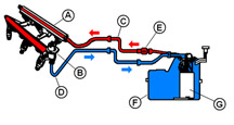
Return System (fig. 2) -- In a return fuel system, fuel travels thought
the entire fuel rail, and unused fuel passes through the regulator and
back to the fuel tank.
A Fuel Rail
B Pressure Regulator
C Pressure Side
D Return Side
E Filter
F Tank
G Pump
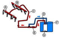
Semi-Returnless System (fig. 3) --
In semi-returnless systems, fuel travels a short distance outside the
fuel tank to an underbody-mounted pressure
regulator/fuel filter assembly. Returned fuel does not travel through
the engine’s fuel rail, decreasing the amount of heat it’s
exposed to.
A Fuel Rail
B Pulsation Damper
C Feed Pipe
D Return Pipe
E Filter
F Regulator
G Pump
Returnless System -- In a returnless system, the regulator is in fuel
tank. Excess fuel returns directly to the fuel tank. The filter may be
in the tank, inside the pump module. Environmental regulations have made
the returnless fuel system necessary. It keeps fuel cooler, reducing
evaporation and excessive hydrocarbon emissions.
The fuel system is divided into two parts, low pressure and high pressure.
In all three types of systems, the high-pressure side begins at the fuel
pump and ends inside the fuel rail. The low pressure side begins at the
regulator fuel bypass port and ends at the fuel reservoir in the tank.
Returnless systems are characterized by a single high-pressure line that
runs to the engine compartment.
The main difference between the three systems is the location of the
fuel pressure regulator. In return systems, the regulator is in the
engine compartment (on or near the fuel rail) and in returnless and
semi-returnless
systems, it’s in or near the fuel tank.
Regardless of location, the fuel pressure regulator regulates system
pressure by bypassing excess fuel back to the tank. In return and semi-returnless
systems, proper diagnosis of pressure concerns requires testing and inspection
of the regulator and verification that the pump or pump module is delivering
adequate fuel. Inadequate fuel flow may be caused by clogged strainers
or filters, rather than pump failure, especially if fuel starvation symptoms
occur only at low fuel levels or during hot weather.
Fuel Pressure Regulator Operation
There are two types of Delphi fuel pressure regulators on GM vehicles,
Universal Pressure Regulator (UPR) and Mini-Cartridge Regulator (MCP).
GM uses regulators from other suppliers, too, but the designs are similar
and operation is identical.
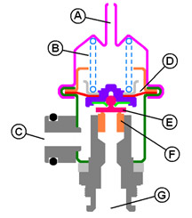
Universal Pressure Regulator (UPR) (fig. 4)
A Vacuum Port
B Spring
C Fuel Out
D Diaphragm
E Valve
F Seat
G Fuel In
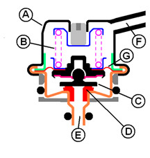
Mini-Cartridge Regulator (MCP) (fig. 5)
A Cover
B Spring
C Valve
D Seat
E Fuel In
F Fuel Out
G Diaphragm
The fuel pump and fuel pressure regulator work in concert to control
fuel pressure supplied to the fuel injectors. At a given voltage, the
fuel pump supplies fuel at a relatively constant rate to the pressure
regulator. Unneeded fuel diverts back to the tank, to match fuel delivery
to engine demand. Fuel flow from the pump varies strongly with voltage.
If system voltage is low, the pump may not receive enough power to fully
pressurize the system or supply the engine at high fuel demand conditions.
Fuel pressure regulators are preset for a particular operating pressure
during assembly, and are not adjustable.
Return System Operation
In most all return systems, the fuel pressure regulator contains a vacuum
chamber that is connected to manifold vacuum and is separated from the
fuel by a diaphragm and valve assembly. The diaphragm has fuel on one
side and engine manifold pressure (vacuum) on the other.
All GM fuel pressure regulators contain a calibrated spring located
in the vaccum chamber side. Fuel pressure in the fuel rail is regulated
by pressurized fuel from the pump acting on the fuel rail side of the
regulator’s diaphragm, pushing against the spring pressure and
manifold pressure (vacuum) on the other side. When the combined force
of vacuum on one side plus pressurized fuel on the diaphragm gets high
enough to overcome spring pressure, the relief valve orifice opens,
reducing rail pressure slightly by bypassing a controlled amount of
fuel to the
fuel tank. When an injector fires, it causes a slight pressure drop
in the rail. In return systems with a vacuum hose connected to the
regulator,
vacuum applied to the regulator keeps the pressure difference (pressure
drop) constant between manifold absolute pressure and supplied fuel
pressure.
Returnless System Operation
Returnless systems operate similarly, but fuel rail pressure decreases
slightly with increasing fuel demand. Fuel pressure does not vary with
manifold vacuum because the regulator is referenced to atmosphere, not
to manifold vacuum. Except for the lack of a vacuum reference, fuel pressure
regulators in returnless systems work just like they do in return fuel
systems. The calibration of the PCM is modified to look at changes in
MAP and vary the pulse width of the fuel injectors to adapt to varying
engine loads.
Fuel Pressure Regulator Common Problems
TIP: These conditions apply to return or semi-return systems.
Leaks -- Regulators can leak internally or externally.
An internal leak is usually caused by a crack in the diaphragm. An
internal leak can be
diagnosed by removing the vacuum hose and checking for fuel seepage
on the outlet tube or the vacuum line. Place a clear piece of vacuum
hose
over the vacuum orifice for a short period of time (15 – 30 minutes).
If fuel rises up in the hose, the regulator is leaking and needs to
be replaced.
Common customer complaints that suggest a leaking regulator are extended
crank and fuel odor. More diagnostic tips will be given later.
Noise -- Regulator related noise may be system oriented or the regulator
itself. Hold a stethoscope on the regulator and listen for the noise
the customer is concerned about. If the regulator is noisy, replace it.
TIP: A noisy regulator may be improperly diagnosed as a noisy alternator.
Disconnecting the alternator is not a good test for isolating noise issues.
System voltage will drop, which causes the fuel pump to create lower
pressure, eliminating the fuel pressure regulator noise.
Temporarily disconnect the vacuum hose from the regulator if it has one,
which slightly raises controlled fuel pressure. If the regulator has
no vacuum hose, connect the fuel shutoff valve special tools listed in
SI and slightly close either valve to alter controlled pressure. DO NOT
fully close either valve when the pump is running, as regulator or pump
damage could occur.
With either procedure, if the noise is gone, the problem is not the alternator.
Be sure to reconnect the vacuum hose if it was disconnected.
TIP: A regulator that is noisy on one vehicle may not be noisy if placed
on another vehicle. And a noisy regulator may be quiet for awhile when
removed and inspected on the same vehicle.
Fuel Injectors
An injector operates on 12 volts and delivers fuel when opened. Voltage
is supplied to the injector when the key is turned on. Some vehicles
have the voltage side of the injector circuit connected to the fuel pump
relay. Therefore the injectors will not receive voltage unless the fuel
pump is energized. The PCM controls the ground circuit to complete the
path for current to flow.
You may suspect an injector is not working if there is a misfire with
a code and a dead skip, and the spark is good. Check for voltage to the
injector and check that the PCM has the ability to pulse the injector
on and off.
TIP: The recommended
test for a complete electrical circuit to the injector utilizes a noid
light. Simply disconnect the wire harness connector,
plug in the noid light, and crank the engine. If the light flashes,
voltage to the injector and the PCM’s ability to turn the injector
on and off are good.
TIP: The noid light does not have the same resistance as the injector
and may not draw the same current. A high resistance circuit may not
affect the noid light as much as it would an injector.
Two causes of intermittent injector operation were covered in past
TechLink articles: ‘fretting corrosion’ in June, 2003 and
injector partially restricted in December, 2002. If you suspect either
of these
conditions, refer to the TechLink article or a bulletin that advises
you on how to test for these conditions.
TIP: If you perform a balance test to find a tricky injector misfire,
be sure to use the kPa scale on your pressure gauge and not the psi scale.
Fuel Pumps
The fuel pump provides fuel flow and pressure to meet engine requirements
under a wide variety of conditions. These functions must be met without
creating undesirable noise, vibration, overpressure, or EMI/RFI in the
vehicle.
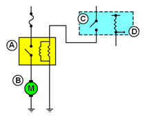
Typical fuel pump schematic (fig. 6)
A Fuel pump relay
B Fuel pump
C Fuel pump relay control
D Fuel level sensor signal
When the ignition key is turned on, the PCM sends voltage to the fuel
pump relay and cycles the fuel pump for 2 seconds. If the PCM does not
see ignition reference pulses, it turns the fuel pump off. Other inputs
may also be involved on some vehicles.
TIP: If you
have concerns about fuel pump operation, go back to the basics, check
the schematic for the vehicle you’re working on, and understand
how the system operates before you start replacing components.
TIP: In the fuel pump circuit, grounds are critical. Ground connections
must be clean and tight.
A fuel pump is designed to operate on numerous fuel compositions in a
global marketplace. The pump must deliver a specific volume and pressure
required for each application. If the pump does not deliver enough volume,
a pressure drop occurs and the vehicle will experience lean combustion
during high fuel demand conditions. If the pump delivers too much flow,
a larger current draw takes place and the fuel that travels through the
system heats up and creates excessive hydrocarbon vapors.
Currently, there are three types of electric fuel pumps used in GM vehicles.
They are the turbine, rollervane and G-rotor types. Although the pumping
section of each of these pumps is different, the main purpose of the
pump is the same -- to provide adequate fuel flow and pressure to the
engine under all operating conditions. For diagnostic purposes, fuel
pressure values are most important for quick and accuate fuel pump diagnosis.
TIP: Current draw readings on the vehicle are not an accurate indicator
of fuel pump condition. There are numerous variables, outside the fuel
pump, which can affect the accuracy of these readings. Electric fuel
pump current values are typically not published for on-vehicle diagnosis.
Modular Reservoir Assembly (MRA) (fig. 7)
A Cover
B Seal
C Reservoir
D Strainer
E Fuel level sensor
F Strainer
G Pump
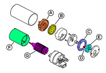
Typical Rollervane Pump (fig. 8)
A Inlet
B Impeller
C Ring (eccentric)
D Roller
E Rotor
F Magnets
G Armature
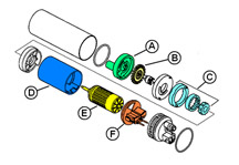
Typical G-Rotor Pump (fig. 9)
A Inlet body
B Impeller
C Gerotor assembly
D Magnet assembly
E Armature
F Brush assembly
Because the fuel pump is located in the fuel tank, quick visual checks
may be difficult. To determine if the fuel pump is working at all, hook
up the Tech 2 and a fuel pressure gauge and cycle the pump on a couple
times. If fuel pressure readings are within specification, you know the
pump is working. If there is no fuel pressure, check for a loss of voltage
to the pump. Wiring can become corroded, loose or broken. Make electrical
repairs according to SI.
If the pump runs when commanded on with the Tech 2 and you still suspect
poor fuel pump performance, look for dirt or rust which could cause the
pump to wear out prematurely.They can also cause the pump check valve
to stick open, leading to hard starting, especially when the engine is
hot. Rust is always caused by water, either from the fuel source, by
condensation or by ingestion of water by the fuel system. If the vehicle
is used under extreme operating conditions (such as off-road), water
and dirt may be ingested through the canister vent system.
Fuel lubricates and cools the pump. Driving the vehicle frequently with
a very low fuel level in the tank can starve the pump of lubrication
and cooling, which can accelerate wear and condensation, two causes of
pump problems.
If you replace a pump that has failed due to dirt or corrosion, clean
out the fuel tank and lines, to avoid the same damage to the new fuel
pump. Also, replace the fuel filter and clean or replace the pickup
screen. Contamination on the screen cannot be seen without magnification.
Newer
vehicles with a pump module usually have two screens, one on the outside
of the module and one on the pump inside the module. Both screens may
block, but the screen on the inside of the module is not serviceable.
So the module must be replaced even if the pump itself is still functional.
Dirt visible inside the module “bucket” is an indication
that both strainers may be blocked. If contamination is in the fuel tank,
it’s most likely to be in other locations in the fuel system. It’s
a good idea to check for contaminants in the fuel rail and fuel lines
also.
Watch for Fuel System Diagnosis, part II, in an upcoming issue.
- Thanks to Dan Wimer and Bob Halsall
|
figure
2
|
figure
3 |
figure
4 |
figure
5
|
figure
6 |
| |
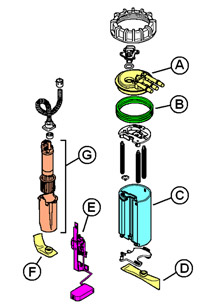
figure 7 |
figure
8
|
figure
9 |
| |
|
|
Floor
Pan Repair Kit
|
This
information applies to various Buick LeSabre and Riviera, Cadillac
Seville and DeVille, Oldsmobile Aurora and Pontiac Bonneville models
between 2000 and present.
For these vehicles, Bulletin 99-06-03-009A contains information for repairing
the floor pan in the area where the battery is located. Damage may result
from weeping of acid from the battery or dislodged vent tube.
To complete this repair, you will need the materials in the table below.
Follow the procedure in the bulletin.
- Thanks to Bill Denton
Part Number |
Description |
12482411 |
Panel Kit -- Floor Pan Repair |
12378567 (US) or 88901675 (Canada) |
GM Metal Bonding Adhesive* |
* or Fusor 108B Metal Bonding Adhesive (Medium Set)
and applicator 103. Contact Fusor at 1.800.234.3876, ext. 3, or
www.fusor.com. |
|
|
|
| return
to Table of Contents |
| |
| Coolant
Loss, Milky Oil |
This
condition can affect some 2000-03 Buick LeSabre, Park Avenue, Regal,
Chevrolet Impala, Monte Carlo, Pontiac Bonneville, Grand Prix with
3.8L V6 Engine (VIN K -- RPO L36).
According to bulletin 03-06-01-016, coolant may leak past the intermediate
intake or throttle body gaskets.
Owners may comment about various symptoms of lost coolant, including
a milky substance on the oil fill cap or dipstick.
The repair kit includes both gaskets. It’s recommended to replace
the thottle body nuts with a new design that improves torque retention.
Medium strength threadlocker is also required.
TIP: Do not replace the upper intake manifold unless a specific driveability
condition and related DTC are noted.
-
Thanks to John Fletcher |
| |
| return
to Table of Contents |
|
| Module
Application and Programming for 2003 |
There
are a number of modules included on cars and trucks that need to
be configured to the vehicle when a replacement is installed. For
your convenience, the accompanying table (click
here) covers all
cars and light duty trucks for the 2003 model year. The table indicates
the type of action required; you must refer to SI for procedures
and details.
The modules listed across the top of the table require configuring to
the vehicle after installation. All of the vehicles are listed in the
left column. Here’s how to interpret the symbols in the table.
- S indicates need for SPS (service programming).
- O indicates set-up required with or without Tech 2
- A indicates actuator set-up is required.
- T indicates an on-vehicle tire pressure monitor programming procedure
is required using special tool J-41760
- # indicates vehicles produced after January 31, 2003 which no longer
require SPS programming
These symbol interpretations are also given in the bottom-left corner
of the table.
The following modules may be installed on certain vehicles, but require
no action, so they are not included in the table:
- Heated Seat Module
- Head Up Display
- Rear Park Assist
- Driver Information Center
- CD Changer
-
Thanks to Lindsey Beauchamp |
| return
to Table of Contents |
|
| New
Monthly Feature Coming |
Beginning
with the September issue, look for the Programming and Setup Corner.
This new feature will discuss a different programming or setup issue
each month.
TIP: This new feature will supplement related supporting information
in SI.
|
| |
| return
to Table of Contents |
|
| GMLAN
Wire Repair |
Beginning this year, a number of GM vehicles will be equipped with a
new serial data system called GMLAN (TechLink, March 2003). Much
new information will be shared about GMLAN and how it functions,
from the GM Technical College and other TechLink articles. Two types
of GMLAN Serial Data Networks can be applied to a vehicle, Low Speed
GMLAN and High Speed GMLAN.
Low Speed GMLAN carries body control serial data messages around the
vehicle. This network is wired with a single wire between modules and
functions at a relatively low speed. For higher priority messages, High
Speed GMLAN may be employed to provide serial data messaging between
different powertrain and chassis controllers. The High Speed GMLAN Network
is wired with two wires in a twisted pair configuration.
TIP: This twisting is critical to protect the network from
outside RF signals and also to prevent radiation of RF interference from
the network.
These problems exist on class 2 serial data networks, but are more critical
on GMLAN Networks, and are extremely critical on the two-wire High Speed
GMLAN network.
A vehicle with GMLAN may have two different serial data networks (the
2004 Chevrolet Malibu). Some vehicles may have only one GMLAN Network
(the 2004 Cadillac XLR, some 2004 Cadillac CTSs and the 2004 Cadillac
SRX).
This article is to remind you that repair of GMLAN wiring must maintain
the integrity of the original network to minimize the risk of outside
RF interference with messaging on the network(s) or having the network
cause noise audible through the radio.
The key things to remember are:
1. Wire repair procedures remain the same as for any other wire repair.
2. The network wire length after repair must be the same length (or very
close to the same) as before the repair.
3. If the network is made up of a twisted pair of wires, the twist must
be maintained or re-created after the repair -- usually one twist per
inch (25 mm).
When making a wire repair such as an open circuit, use the appropriate
crimp and seal splice, and maintain the twist in a High Speed GMLAN circuit
as much as possible.
If splicing a pigtail to a Low Speed GMLAN circuit, use care to maintain
the original length of the circuit. If the circuit is a High Speed GMLAN
twisted pair, then factor that into the amount of wire you use from the
pigtail. Also be sure to offset the crimp and seal splices and position
them to maintain the one twist per inch (25 mm).
A service terminal may be used, as long as you do not untwist any more
than is necessary in a High Speed GMLAN circuit to make the repair.
- Thanks to John Roberts |
| |
|
return
to Table of Contents |
|
| Front
Stabilizer Shaft Installation |
This
condition affects 2003 TrailBlazers, Envoys and Bravadas with the
4.2L L6 engine, with the stabilizer shaft running through the frame.
TIP: On earlier models, the stabilizer is mounted to the front of the
frame.
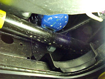
On these vehicles, it is possible to install the front stabilizer shaft
upside down. If this occurs, the shaft may contact and damage the engine
oil filter (fig. 10).
There is a bend in the shaft for clearance in the area of the oil filter.
When the shaft is installed correctly, it should bend away from the engine.
TIP: There may be a label on the shaft. If so, it should be on the LH
side.
- Thanks to Steve Hathaway |
| 
figure
10
|
| return
to Table of Contents |
|
| Diesel
Engine Training |
The
interim 2004 Duramax 6600 diesel engine (RPO LLY) becomes available
January 2004. Though similar to the current production Duramax 6600,
this engine offers some significant differences. The GM Service Technical
College (STC) will offer an updated Diesel Engine Performance course
to reflect the changes. Refreshed and updated CBT, IDL, and Hands-on
course components will be released successively beginning April 2004.
To enable technicians to promptly offer service to customers with the
new LLY Duramax 6600 engine, GM STC will release a supplemental video
course in December of 2003 that focuses on this new engine configuration.
Technicians with credit in any of the current Diesel Engine Performance
2001 course components may take this video course to receive a cross-credit
to the updated course components.
Technicians are encouraged to participate in opportunities to complete
the training components within the Diesel Engine Performance curriculum
path. This curriculum path provides the foundation for December’s
supplemental video. This strategy will not only increase the dealership’s
overall Service Training Standard score, but will help ensure that the
technicians are prepared for LLY Duramax 6600 customer concerns and able
to fix them right the first time. Dealers that complete the current standards
before December will be in an excellent position to address the needs
of the LLY Duramax 6600 customers. Additional communication about the
new courses will be available a few weeks before their release.
- Thanks to Steve Sternicki
Current
Course |
Supplemental
Course
(Released December 2003) |
Updated
Course
(First component released
April 2004) |
Diesel
Engine Performance
2001 (W, D, H) |
Duramax
6600: 04i Engine Performance Updates
(Video and Booklet) |
Duramax
6600: Diesel Engine Performance |
|
|
|
| return
to Table of Contents |
|
| Compass
Erratic or Inaccurate |
According
to upcoming bulletin 03-08-49-008, owners of some 1999-2001 Blazers,
Jimmys and Bravadas may comment that the compass is erratic or inaccurate
while operating the power sunroof. The compass may stay erratic or
inaccurate while the power sunroof is open.
The sunroof module cable may become magnetized with the operation of
the roof, producing a false signal to the compass sensor. Relocate the
compass sensor by replacing the compass sensor bracket with part number
15106819.
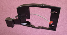
TIP: The compass sensor is located to the right side of the original
bracket; it is located forward of the replacement bracket (fig.
11).
TIP: The supply is limited, so do not order parts for stock.
It is necessary to remove the driver information center and lower the
headliner for access to the compass sensor mounting bracket.
While the headliner is lowered, follow the instructions in the bulletin
for notching the headliner to provide clearance for the compass sensor.
Refer to the appropriate SI documents for component removal and installation.
-
Thanks to Dan Oden and TJ Smith |
figure
11 |
return
to Table of Contents
|
|
 Car
Issues – Fix It Right The First Time Car
Issues – Fix It Right The First Time |
Model
Year(s)
|
Vehicle
Line(s) --
Condition
|
Do
This
|
Don’t
Do This
|
Reference
Information / Bulletin
|
2001-2003
|
3800
L36 – Coolant Leak at Intake Manifold
|
Replace
the intermediate (upper) intake gasket
|
Replace
the intake manifold assembly
|
Bulletin
in process
VME to field 5/30/03
TechLink article in June
|
1998-2003
|
Seville – Rear
Seat HVAC Controls
|
Replace
the knob only
|
Replace
the entire rear seat blower switch assembly
|
03-01-39-001A
|
2000-2003
|
Cavalier/Sunfire/Grand
Am/Alero/Malibu – Inaccurate Fuel Gauge
|
Replace
sensor card for fuel gauge – accuracy issue
|
Replace
fuel sender/pump assembly
|
01-06-04-008D
|
1999-2003
|
Grand
Am/Alero – Window Disengagement, Broken Clips
|
Replace
sash clip only
|
Replace
door glass assembly
|
01-08-64-018
|
1997-2003
|
Grand
Am/Alero/Malibu – Brake Pulsation
|
Turn
rotor and brake align procedure
|
Replace
brake rotor for pulsation
|
00–05-23-002
01-05-23-001 (Know How Video #15040.01B)
|
1997-2003
|
Venture/Montana/Silhouette –Windshield
Water Leaks
|
Refer
to specific bulletin procedures for diagnosis
|
Assume
that leak came from the windshield sealing
|
01-08-57-006
|
1997-2003
|
Century/Regal – HVAC
Operation, No “Auto” Light
|
Normal
in full heat or cold setting
|
Replace
HVAC control head for “Auto” light
|
99-01-39-007B
|
1999-2002
|
Corvette – Fuel
Gauge Intermittently Goes to Empty
|
Install
revised software
|
Replace
fuel senders or I/P cluster
|
02-06-04-010
(2002 MY)
1999-2001 MY software released – bulletin not yet updated
|
2003
|
All
cars with 4T40/45E, 4T56E and 4T80E – Code P0742
|
Replace
TCC PWM Solenoid
|
Replace
transmission or valve body assembly
|
02-07-30-039B
|
2002-2004
|
L61
EcoTech 4 Cylinder – Engine
|
Replace
Cylinder Bore Liner
|
Replace
Engine
|
03-06-01-018
|
|
| return
to Table of Contents |
|
|
 Truck
Issues – Fix It Right The First Time Truck
Issues – Fix It Right The First Time
|
Model
Year(s)
|
Vehicle
Line(s) --
Condition
|
Do
This
|
Don’t
Do This
|
Reference
Information / Bulletin
|
2003
|
Fullsize
Pickups and Utilities – Transfer Case Service Light
|
Replace
encoder motor sensor and reprogram TCCM
|
Replace
the module, encoder motor or transfer case for DTCs C0327,
P0836, P0500
|
03-04-21-001B
|
1999-2002
|
Fullsize
Pickups and Utilities – Throttle Body Sticks
|
Clean
throttle body adjust blade and insert plugs
|
Replace
throttle body
|
02-06-04-054B
and parts restriction
|
2003
|
Fullsize
Pickups – 6.6L Diesel Engine ECM
|
Follow
SI and bulletins for proper diagnostics for P0181. Refer to
the Owner’s Manual (block heater and front cover)
|
Replace
ECM (DTCs P0540 and P0181) unless diagnostics confirm need
to replace
|
02-06-04-048,
03-06-04-021, 02-06-04-058 and parts restriction
|
2003
|
Silverado,
Sierra, Savana, Express > 8600 GVW – ABS Lamp On
|
Reflash
for code C0550
|
Replace
ABS module
|
03-05-25-003
|
2002-2003
|
Envoy,
Envoy XL, Bravada with G67 – Low in Rear
|
Replace
check valve service kit
|
Replace
air suspension compressor
|
02-03-99-001
|
2002-2003
|
All
TrailBlazers, All Envoys, Bravada – Mirror Erratic Return
|
Replace
mirror actuator and reprogram module
|
Replace
outside mirror assembly
|
02-08-64-008
02-08-64-021
|
1999-2003
|
Fullsize
and Midsize Utilities – Sunroof
|
Install
clip or mechanism kits. GMSPO has component parts.
|
Replace
sunroof
|
02-08-67-009
03-08-67-004
|
1999-2003
|
Fullsize
Pickups and Utilities, Midsize Utilities – Noise on Steering
|
Lube
I-Shaft
|
Replace
I-Shaft
|
00-02-35-003B
02-02-35-006A
|
1999-2003
|
TrailBlazer,
Envoy, Bravada without G67 – Moan/Boom
|
Replace
rear coil springs
|
Repurchase
vehicle for rear axle vibration/boom noise
|
02-03-09-002A
|
2002-2003
|
All
TrailBlazers, All Envoys, Bravada – Inoperative Tail
Light
|
Replace
tail lamp circuit board and bulb
|
Replace
rear tail lamp assembly for brake light
|
03-08-42-006
|
|
| return
to Table of Contents |
|
|
|
Know-How
Broadcasts for September
|
| |
 |
| Know-How
Broadcasts for September |
|
10270.09D
Emerging Issues
|
September
11, 2003
|
9:00
AM, 12:30 PM,
3:30 PM
Eastern Time
|
|
10270.21D – New
Model Features - 2004 Colorado and Canyon
|
September
25, 2003
|
9:00
AM, 12:30 PM,
3:30 PM
Eastern Time
|
| -
Thanks to Tracy Timmerman |
|
|
| return
to Table of Contents |
| |
