|
|
Note: Clicking
on any picture or illustration will open a larger version of that art.
|
|
Corvette
Z06 Dry Sump Oiling System |
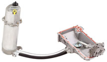
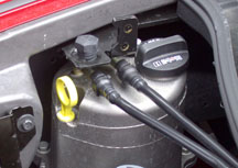
The
Corvette Z06’s LS7 engine (fig. 1)
has a dry sump oiling system designed to keep the engine fully lubricated
during the high cornering loads the Corvette Z06 is capable of producing.
Ths LS7’s dry sump system was developed and tested on racetracks
in the U.S. and Europe, including Germany’s famed Nürburgring.
And while dry sump oiling is common in racing cars, the Corvette Z06
is one of just a handful of production vehicles -- and the only production
Corvette -- to incorporate such a high-performance oiling system.
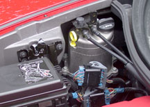
What is a Dry Sump Oiling System?
Most automotive engines use a wet sump sytem, in which all of the engine
oil is stored inside the crankcase in the oil pan. In a dry sump oiling
system (fig.2), engine oil is stored in
a reservoir external to the engine, so the crankcase contains only a
minimal amount of oil at all times.
What are the Advantages of a Dry Sump System?
In an engine with a conventional wet sump oil pan, the oil can slosh
away from the oil pump pickup tube during high dynamic maneuvers like
cornering, braking and accelerating. This starves the engine of oil,
causing bearing damage or catastrophic engine failure.
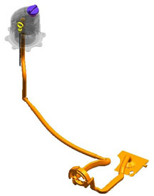
The dry sump system stores engine oil in a tall and narrow oil reservoir
(fig. 3). This shape prevents oil from
sloshing away from, or uncovering, the oil pickup, even under extremely
high dynamic maneuvers. The dry sump system enables increases to the
dynamic capabilities of the vehicle, which is why racing cars and exotic
sports cars use this type of oil system.
Additionally, oil aeration is lower in a dry sump system, because the
oil spends less time in the presence of the crankcase windage. Oil delivered
to the bearings is typically superior to that of a wet sump system.
Finally, without the need for a conventional sump, the engine can be
placed lower in the vehicle, effectively lowering the center of gravity
of the vehicle.
How Does a Dry Sump System Work?
In the LS7 engine, two oil pump sets (scavenge pump and supply pump)
are located in the same housing on the nose of the crankshaft. The location
is common with the oil pump in other small block engines.
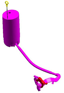
The scavenge pump removes engine oil and air from the sump and pumps
both to an external reservoir for conditioning and storage
(fig. 4).
The oil is directed to the top of the reservoir, where it is allowed
to spill onto a spiral-shaped baffle. Crankcase gases and air are separated
from the oil and are returned by the PCV system to the engine, where
they are burned. The deaerated and conditioned oil collects in the bottom
of the reservoir, ready for use.
The supply pump (fig. 5) draws the conditioned
oil from the reservoir, pressurizes it, and feeds it to the engine by
way of the oil filter and oil cooler. After the oil passes through the
engine, it again flows into the sump to be returned by the scavenge
pump to the reservoir once again.
Checking the Oil Level
The engine must be warmed up. Cold oil will not give a correct oil level
reading.
After the engine is warmed up to at least 175°F (80°C), shut
off the engine. Checking the oil with the engine running will result
in an incorrect reading.
Wait for 5 minutes (but not more than 20 minutes), to allow the oil
to drain and settle.
Pull the dipstick with the yellow handle (fig.
6) from the reservoir, and clean it with a lint-free cloth. Then
push it back in all the way until it stops. Remove it again, keeping
the tip down, and note the oil level on the crosshatched area.
An oil level within the crosshatched area is normal. If the level is
below the crosshatched area, add 1 quart (0.96 L) of 5W30 Mobil 1 synthetic
oil through the black oil reservoir fill cap (fig.
6) and take another reading.
TIP: Do not overfill the reservoir, as this may
result in excessive oil consumption. Oil levels above the crosshatched
area may degrade lubrication system performance.
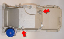
Oil Change Procedure
Remove the two drain plugs from the engine oil pan
(fig. 7). One is located on the left side of the oil pan near
the oil filter. This plug drains the small amount of residual oil from
the engine oil pan, approximately 1 quart (0.96 L). The other drain
plug is located on the front of the oil pan. This plug drains the external
reservoir and hose assembly. Also remove the engine oil filter.
Once the oil has been drained from the engine and reservoir, replace
the engine oil filter with a new PF48 oil filter and tighten to 25 Nm
(18 lb ft).
Replace both oil drain plugs and tighten to 25 Nm (18 lb ft).
Fill the oil through the oil fill cap in the top of the dry sump reservoir.
The total service fill, with a dry filter, is 8 quarts (7.57 L) of 5W30
Mobil 1 synthetic engine oil.
Replace the oil fill cap and start the engine. Let it run at idle for
at least 15 seconds to circulate the fresh engine oil through the lubrication
system. (This is similar to running an engine after a radiator fill,
to purge air from the system.)
Check the oil level according to the instructions above. The oil change
is now complete.
TIP: The owner’s manual may contain a slightly
different procedure, which calls for filling 7 quarts, running the engine
then shutting off, and finally filling 1 additional quart. This procedure
may be used, although it is not necessary.
TIP: There is a cap on the right valve cover under
the decorative cover. Attempting to remove this cap can break the retaining
tabs, requiring removal of the valve cover to retrieve broken pieces.
Under no circumstances should you attempt to fill the engine oil system
through this cap.
-
Thanks to Dan Hommes and Ron Minoletti |

figure
1 |
figure
2 |
figure
3 |
figure
4 |
figure
5
|
figure
6
|
figure
7 |
| return
to Table of Contents |
|
|
| Tech
2 Extended Warranty |
Your Tech 2 automatically comes with a two-year manufacturer’s
Express Exchange Warranty. Did you know that you can ensure the same
reliable service on your Tech 2 by extending the manufacturers warranty?
GM Dealer Equipment (GMDE) is offering a special promotion on extended
warranties during the third quarter of 2005. Purchase a two-year extended
warranty and get the third year free.
|
Warranty
Service
(with Express Exchange Warranty) |
Regular
Repair
(without warranty) |
| Repair Time |
24 hours (replacement
units shipped to arrive the following morning for requests received
before 3:00 pm PST |
4-6 days |
| Administration |
None: One phone
call gets you a replacement unit the next day and return shipping
arrangements |
Delays in getting
repaired unit; i.e., issuing checks, etc. |
Costs --
U.S. |
1 Year $150.00
2 Year $280.00
3 Year $407.00 *
* Purchase during 3rd Quarter 2005 and pay only $280.00 |
Approximately
$785.00 average repair plus return shipping. Dealership service
department losses due to not having Tech 2 for 4-6 days |
| Costs -- Canada |
1 Year $214.00
CD
2 Year $409.00 CD
3 Year $598.00 CD*
* Purchase during 3rd Quarter 2005 and pay only $409.00 |
Approximately
$973.00 CD average repair plus return shipping. Dealership service
department losses due to not having Tech 2 for 4-6 days |
During
the term of your warranty coverage, not only are there no charges for
repairs performed to your Tech 2, you will be guaranteed a 24 hour express
exchange warranty replacement service (warranty does not cover cables,
adapters and the 32 meg card). If you have a problem with your Tech
2, simply call the GM Techline Customer Support Center (TCSC) at 800.828.6860
and you will receive an express exchange replacement unit the next business
day at no additional charge.
Contact 1.800.GM.TOOLS (468-6657, option 1, option 3) for answers to
any questions.
TIP: Please provide
the following promotional code to receive this great offer: DES3RDT2.
- Thanks to Sue Sulewski |
|
|
| |
|
|
Programming Tips |
Technicians
continue to report occasional problems with incomplete programming events
or errors. This leads to damaged controllers and unnecessarily high
warranty. Here are tips that may help prevent some of these problems.
Insufficient Battery Voltage -- The proper battery
voltage is critical to programming. If voltage drops too low at the
end of the programming event, calibration files or VIN data may not
be written, causing problems or failure.
Be sure the battery is fully charged before starting the programming.
If the battery voltage is questionable, you can use a Midtronics PSC
charger during programming (July 2005 TechLink). At this time, GM has
not validated any other charger for this purpose.
Not Turning Accessories Off -- Before programming,
turn off all electrical devices, such as headlights, radio, HVAC, etc.
And during the programming event, do not turn on any electrical devices.
Not Using Current Software -- You must use the most
current Tech 2 software release and the most current TIS software release.
To be sure you are always using the latest data, you must update your
Techline terminal as soon as you receive the new software.
Not Waiting -- Before performing a programming event,
you must turn the ignition key on. Do not begin programming right away.
It’s critical to wait until all modules on the vehicle have “awakened”
before beginning. (This is the same principle as waiting for any computer
to “boot up”. You cannot start to access applications on
your PC until it fully boots up. The same applies for any vehicle systems
with multiple modules.)
If you try too soon, you will get a No Communication message on the
Tech 2. A good rule of thumb is to observe the instrument panel lights
and tones. When everything stops, you can safely proceed. Plug in your
Tech 2 (and CANdi module if required).
Not Cycling Ignition -- When working on a GMLAN system,
you must cycle the ignition off and back on after programming each module.
Do not begin programming a second module without turning the ignition
off and on.
TIP: During the ignition OFF time, avoid opening
and closing the doors for 30 seconds until the controller can write
the new values.
Voltage Held in Components -- Some components contain
capacitors, which can store voltage after being turned off. If stored
voltage is released by a module while you programming another module,
it could cause confusion on the data bus, causing U codes to set. To
prevent this, you may be instructed to disconnect the battery cables
and touch them together. This drains the stored voltage from capacitors.
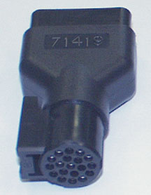
Using the Wrong Tech 2 Adapter -- There are three 16-pin
adapters that have been used with the Tech 2. At a glance, they all
look the same (fig. 8).
Do not use adapter p/n 71419.
You can use either of the adapters numbered GM 3000098. They have been
manufactured by two different vendors. One of them is coded VTX 02002955,
and the other is coded HP 5063-3255. Either of these will work with
CANdi modules.
-
Thanks to Mark Stesney |
figure
8
|
| return
to Table of Contents |
|
| Radio
Labor Code |
When servicing a radio under warranty, be sure to use the correct labor
code. Do not use the XM radio receiver code when sending a regular or
navigation radio.
-
Thanks to Jim Hughes
Radio
Type |
Labor
Code |
Definition |
Regular
Radio or Navigation Radio |
R0760 |
Remove,
Repair and Replace |
R0762 |
Remove |
R0763 |
Reinstall |
XM
Radio Receiver |
R5600 |
Replace |
|
| |
| return
to Table of Contents |
|
| Remote
Vehicle Start Accessory Kit Followup |
The June 2005 issue of TechLink
introduced you to the Remote Vehicle Start Accessory Kit, which can
be dealer-installed on certain vehicles. Here are some reminders and
some new information to help the installation go well.
During Installation
- Be sure you are using the latest version of Tech 2 and TIS software.
- The vehicle’s battery must be fully charged before programming
the module.
- The kit comes with two additional key fobs (fig.
9) (the vehicle was delivered with two original key fobs). When
programming the fobs using the Tech 2, you should program the new fobs
in slots 1 and 2, to permit diagnosis of the new fobs (Impala, Monte
Carlo, and Lucerne only). You can program the original fobs in slots
3 and 4.
TIP: Remember,
the original fobs can be used only for remote lock and unlock; they
cannot be used for remote start.
After Installing
Here are some points to keep in mind when checking system operation
after installation.
- The hood must be closed for remote start to operate. If you attempt
to check the installation with the hood open, the system will not work.
- Each remote start event times out after 10 minutes of engine operation.
Then the key fob must be pressed again.
- Remote start can be used only twice, then the system must be reset.
Do not interpret this as a malfunction. Turn the ignition on with the
ignition key to reset the system.
-
Thanks to Mark Stesney |

figure
9
|
| return
to Table of Contents |
|
Enhanced
Master Technician Certification Program for 2005
(not applicable in Canada) |
Becoming
a GM Master Certified Technician means you’ve earned the right
as a GM expert in a certification area and have demonstrated you have
the skills and knowledge to “fix it right the first time.”
The GM Service Technical College (STC) is introducing simulations as
part of some 2005 GM Master Technician Certification (MTC) Assessments,
to challenge and evaluate technicians’ diagnostic skills.
GM service technician training is structured around a standard, performance-based
curriculum. The curriculum blends in-dealership training with training
at various off-site locations. In the dealership, the technician acquires
component, systems, and diagnostic knowledge via Web Based Training
(WBT) and Interactive Distance Learning (IDL). The technician can then
practice and demonstrate the application of skills at various training
locations by attending Hands-On courses. The capstone of this standard
curriculum is GM Master Technician Certification (MTC) in each automotive
or body service area.
It is very important that you are adequately prepared for the GM MTC
Assessment. Here are a few tips on preparing for this challenging event:
- If traveling, arrive the day before the assessment.
- Review all WBT courses already taken
- Review all IDL materials received
- Talk to the service manager about any area that could be improved,
including Service Repair documentation
- Review GM MTC Assessment Prep Guide at http://www.gmstc.com/home.asp
- Review the Service Information website, specifically for the Strategy
Based Diagnostics (SBD) process.
- Find an expert at the dealership who can assist in the certification
area
- Investigate and complete ASE certification in the subject matter area
IMPORTANT: If
you have never taken a Hands-On course, or an on-line Hands-On simulation,
you should complete one in the subject matter area before attending
the Certification Assessment. If an on-line Hands-On simulation is not
offered in the subject matter area, familiarize yourself with a simulation
as close to that area as possible.
The following Master Technician Certification categories include a Hands-On
Simulation:
- Brakes
- Gas Engine Performance
- Diesel Engine Performance
- Mechanical / Electrical Body
- Electrical / Electronics
- Steering & Suspension
To access and utilize the GM STC Hands-On simulations, follow these
instructions:
1. Access the GM Training Website at www.gmtraining.com
2. Select Catalog>Catalog Search at the main menu and perform a search
as illustrated below (fig. 10)
3. Select “Course Number” from the drop down menu
4. Select “Ends with”
5. Type in “S” for simulations
6. Select W-Web-Based Training (CBT) from the drop down menu
7. A complied list of results will show at the bottom of the screen.
NOTES:
- The Certification Assessment is similar to the structure of a Hands-On
course, but without the guidance from an instructor, or in the case
of a simulation, a play-by-play coach. Experiencing the Hands-On training
offered today gives the technician a much better idea of what to expect
in Certification Assessment.
- The Master Technician Certification Assessment program has been revised
to include up to seven technicians per session, rather than the previous
five technicians per session.
For more information regarding GM MTC certification, please refer to
the GM Training Website at www.gmtraining.com,
Menu>Resources>Certification.
-
Thanks to Rebecca Farrand |
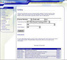
figure 10
|
| return
to Table of Contents |
|
| Common
Architecture |
Common architecture is a term that is being used to describe the next
level of vehicle data communication in GM cars and trucks.
It starts with a common Body Control Module (BCM) that will be used
on numerous GM vehicle platforms. This is combined with an updated version
of GMLAN (the revisions are transparent to the field, and relate to
serial data message size).
The new BCM is flexible, able to accommodate a wide range of vehicle
content and features. It will work on both car and truck platforms,
with or without door modules, with either standard ignition or EZKey
(i.e., XLR or STS).
Common Architecture Rollout
Common architecture will launch in 2006 with the Chevrolet Impala/Monte
Carlo, the Cadillac DTS and the Buick Lucerne. Application expands in
2007 to include all full-size utilities.
Common Architecture BCM Basics
There will be only two BCM variants in production. These two controllers
will be used in multiple applications, reducing the number of service
parts required.
TIP: Always order
the correct part for the vehicle being serviced.
Here are some of the new BCM’s features:
- Seven connectors with 169 terminals.
- Approximately 100 DTCs, depending on vehicle configuration.
- Over 200 Tech 2 data list parameters.
- Approximately 40 Tech 2 output controls (depending on vehicle configuration).
- I/O (input/output) is reconfigurable. For instance, the DTS park brake
switch input is on a different terminal in a different connector than
in the Impala.
- All configuration is via SPS and “as built” data (much
like Powertrain Controllers).
- All BCMs use the same set of core operational software.
- All configurations are determined by calibration files in flash memory.
Different calibrations account for various options and accessories.
Set-Up Procedures
There are only two Tech 2 set up procedures:
- BPP Sensor Calibration
- Setup SDM Primary Key in SDM
TIP: The service
part is non-functional before SPS programming. It will not communicate
with other on-board devices, and the vehicle will not start.
Benefits of Common Architecture
Designed with flexibility in mind, common architecture will bring consistency
to body control systems. Because functionality will be consistent across
many GM platforms, it will be less likely to drive customer complaints
based on normal operation. Reduced service part numbers are another
benefit. In the future, this hardware and software will be easily transportable
to new platforms.
-
Thanks to Gary Clark |
| |
| return
to Table of Contents |
|
| Parking
Brake Light |
Owners
of some 2004-05 Cadillac DeVilles may comment that the brake light on
the instrument panel (I/P) stays illuminated after releasing the parking
brake. This may be caused by a weak return spring located at the rear
of the parking brake cable.
If this conditon occurs, repleace the rear parking brake cables. Rear
parking brake cables (p/n 15236959) contain a more robust return spring.
Refer to Bulletin 05-05-26-001 for details.
-
Thanks to Bill Denton |
| |
| return
to Table of Contents |
|
| Product
Quality Center |
The
Product Quality Center (PQC) was put in place to help GM improve the
quality of its products.
Before the PQC existed, the assembly return program asked dealerships
to attach information to the returned assembly, explaining the concern
and describing what diagnostics were done. Fewer than 25% of the returned
units had any documentation attached. Most of the information was incomplete.
When PQC was instituted, dealers were required to call before the replacement
of an engine, transmission or transfer case assembly. Now, PQC is able
to collect the necessary information in a database.
All current model engines, transmissions and transfer case assemblies
must be returned 100% (and also a sample of past model units). When
Engineering disassembles these units, they refer to the PQC case file.
This gives them all the information they need to determine the root
cause of the failure. In this way,
Engineering has been able to more quickly identify the causes of assembly
failures. In some cases, Engineering contacts the service technician
directly to further understand the cause of a specific failure.
Engineering then makes improvements in the product to eliminate the
cause of the failures. This process has reduced assembly replacements
in GM products by over 30% in three years.
This process has been so effective that it has been expanded to include
other components, including body and IP wiring harnesses. These restrictions
are usually much shorter in duration.
The PQC will continue to be an important part of the engineering failure
analysis process. This, combined with the outstanding cooperation from
dealers, will help GM reach the goal of manufacturing the highest quality
vehicles available in the market.
-
Thanks to Jim Colyer |
| |
| return
to Table of Contents |
|
| Oil
Capacity Chart |
A new oil capacity chart has been posted on the TechLink website. It
includes GM cars and trucks from 1996 through 2006.
On the website, click on the Reference Guides button, then scroll down
to Oil Capacities for 1996-2006. Click to open the
chart.
TIP: An earlier
Oil Capacities chart is still available in the Reference Guides for
GM cars and trucks from 1988 to 2005.
When the chart opens, scroll down the list to locate the vehicle, then
locate the appropriate engine. The oil capacity is listed in both liters
and quarts.
TIP: Pay attention
to footnotes and other supplemental information.
- Thanks to Jerry Garfield |
| |
|
return
to Table of Contents |
|
| Fuel
Filter Clarification |
External fuel filters were used only on C/K trucks
with an L59 engine (E85). These engines were used on utility models
only, from 2002 to 2004.
-
Thanks to Jerry Garfield |
|
return
to Table of Contents |
|
| Integral
Connector Position Assurance (CPA) |
Many
vehicle systems are using connection systems with an integral connector
position assurance (CPA). In Supplemental Inflatable Restraint (SIR)
applications, these CPAs are used to lift the shorting bars from contacting
the connector terminals. This allows the airbag to be shorted before
the connector is removed, to prevent unwanted deployment. After installation,
if the CPA is not in the firmly locked position, a DTC will set for
low resistance.
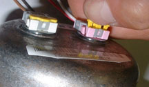
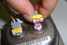
The example here shows a connector and CPA on the inflator assembly
of the 2005 midsize trucks. This is an FCI connection system called
ABX4 which will soon appear on other vehicles. If not operated properly,
this CPA can easily be damaged during removal, which can cause DTCs
to set after the CPA is reinstalled. The information provided here is
to aid in the proper installation and removal of this connector and
CPA.
TIP: An article
in the December 2004 TechLink described a similar situation where the
steering wheel coil assembly CPA is integral to the system and causes
the setting of DTCs when damaged or removed.
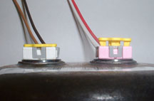
Connector Removal
With your finger or terminal release tool 12094430 from the J-38125
Terminal Repair Kit, apply an upward force on the CPA until the CPA
is in the pre-lock position (approximately 1.7 mm) (fig.
11 and 12).
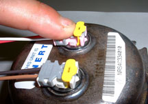
IMPORTANT: Do
not pull the CPA completely out of the connector. If the CPA
is removed completely from the connector assembly, it will be damaged
and must be replaced with a new one.
TIP: Replacement
CPAs will be available in the SIR tray in the terminal repair kit (J-38125)
later this year. Until available, if the CPA needs to be replaced, order
part number 88988974 RETAINER, INFL RST WRG HARN CONN (CPA AT DRIVER
AIRBAG).
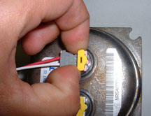
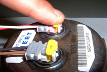
Remove the connector by squeezing the locking tabs while lifting the
connector body (fig. 13 and 14).
TIP: Do not pull
on the harness cable or the yellow CPA as a means of removing the harness
connector. Potential damage could result.
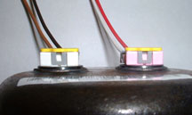
Connector Installation
Align the keyway of the connector to the mating side at the airbag module
initiator (fig. 15).
Press the connector body with your finger to engage the connector (a
tactile feeling or audible click will indicate when it is seated) (fig.
16). Typical mating force is approximately 25 N (5.5 lbs).
TIP:
The CPA must not be moved to the locked position until
the connector is fully mated to the inflator assembly.
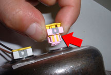
Only after the connector is seated, press the CPA with your finger to
engage the CPA (a tactile feeling or audible click will indicate when
it is seated) (fig. 17 and 18).
TIP: To prevent
damage to the connector and CPA, do not exceed 75 N (16.5 lbs) of force.
Important Finishing Steps
After any SIR system repair, remember to follow these steps.
Reconnect all SIR system components.
Verify that all components, connectors and connector position assurances
(CPAs) are properly mounted.
Use the scan tool to clear the DTCs.
Operate the vehicle within the Conditions for Running the DTC as specified
in SI to ensure that the DTC does not reset.
-
Thanks to Chad O’Brien |
|
figure
11
|
figure
12
|
figure
13
|
figure
14
|
figure
15
|
figure
16
|
figure
17
|
figure
18
|
|
return
to Table of Contents |
|
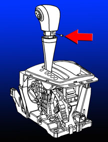
| Loose
Shift Knob |
Some owners of the 2004-06 Chevrolet Malibu and
Malibu Maxx may comment about a loose shift knob.
1. Remove the shift control shaft trim by sliding it downward on the
shift control assembly shaft.
2. Remove the shift knob setscrew and raise the shift knob off of the
shift control assembly shaft (fig. 19).
3. Clean the shift knob setscrew with a wire brush, and apply thread
locking compound Loctite® 242 (GM p/n 12345382, 10953489 in Canada)
to the setscrew.
4. Install the shift knob on the shift control shaft and reinstall the
setscrew. Tighten the shift knob setscrew to 2.5 N·m (22 lb in).
5. Install the shift control shaft trim by pushing up until it snaps
onto the lower portion of the shift knob.
-
Thanks to David MacGillis |
figure
19
|
| return
to Table of Contents |
|
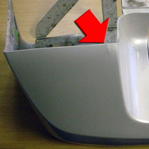
| Running
Board End Cap Installation |
On
2004-05 Cadillac Escalades, running boards are assembled to the vehicle
at the time of vehicle assembly without end caps. The end caps are shipped
loose inside the vehicle with an instruction sheet and necessary fasteners.
TIP: End cap
installation is part of the dealer PDI process and is incorporated in
the PDI time for this vehicle.
The adjustment of the main part of the running board must be performed
during end cap installation. The design of the end cap is sensitive
to the position of the main part of the running board relative to the
vehicle.
The 8 fasteners that secure the boards to the vehicle must be loosened
before installing the end caps. Loosening the boards helps install the
end caps without stress on the part and allows for proper alignment
to the vehicle. Failure to properly align the board to the vehicle during
end cap installation will cause the end cap to crack (fig
20).
-
Thanks to David Roland |
figure
20 |
| return
to Table of Contents |
|
| Service
Brake Booster Message |
This information applies to all full-size 2004 Cadillac, Chevrolet and
GMC trucks and utilities with Hydroboost brake system.
The Service Brake Booster message is used to notify the driver of a
Supplemental Brake Assist (SBA) concern on vehicles equipped with a
vacuum boost brake system. There have been reports of the Service Brake
Booster Message being displayed on vehicles equipped with a Hydroboost
brake system.
During normal diagnostics, a DTC C0136 may be present in the IPC. This
DTC will not be in SI for Sport Utility vehicles, because all Sport
Utilities use Hydroboost brake systems starting in 2004.
This message could be caused by the IPC being programmed incorrectly.
If the IPC was replaced on a previous unrelated repair and was not SPS
programmed, this message will be displayed after the IPC does not receive
a valid state of health signal from the SBA for 5 consecutive ignition
cycles.
To correct this concern, SPS program the IPC. To be sure the vehicle
is repaired, cycle the ignition to off and on at least 5 consecutive
times, delaying in each position at least 30 seconds.
-
Thanks to Jim Will |
| |
| return
to Table of Contents |
|
| Heated
Seats Turn Off |
Owners
of some 2003-2005 Silverado and Sierra trucks equipped with the 6.6L
diesel engine may experience the heated seats turning off after 3 to
5 minutes of operation and DTC B3941 sets. This concern will occur only
on the first start in the morning and both the passenger and drivers
heated seats are turned on at start up. After the heated seats inadvertently
turn off, they can be turned back on and will continue to operate normally
the remainder of the drive cycle.
To correct this concern, reprogram the DSM (Driver Seat Module) with
service calibrations available from Techline on TIS2000 version 6.5
or later available June 13, 2005.
-
Thanks to Jim Will |
| |
|
return
to Table of Contents |
|
| Driveline
Vibration at Highway Speed |
Owners
of some 2005 Chevrolet Kodiak and GMC Topkick C4500/C5500 Conventional
4x4 models with 152-inch wheelbase ( RPO EG9) may experience a driveline
vibration when driving at highway speeds.
These models are built with a single rear propshaft. Engineering has
determined that the original rear axle pinion angle is not the optimum
design angle for the 152-inch wheelbase and may result in some driveline
vibration.
Change the rear axle pinion angle from the as-built 8.1° to the
new 6.1° angle by replacing the original rear axle spring seats
with the following spring seats available from GM Service Parts. Refer
to SI document 1202795.
-
Thanks to Jim Will
| DESCRIPTION |
GM
P/N |
QUANTITY |
Rear Axle Spring Seat
(6.1° pinion angle) |
15640807 |
2 |
|
| |
| return
to Table of Contents |
|
| Transfer
Case Stops Shifting |
This
information applies to 1999-2005 trucks and utilities with an RPO NR4,
NP1, or NP8 transfer case.
The electronic transfer case may stop shifting if the driver tries repeated
shifts in a short period of time.
The software in the transfer case control module has a shift abuse lockout
mode to protect the module and encoder motor. This concern will occur
if the module senses repeated shift requests in a short period of time.
If the driver continuously tries to shift in and out of different modes,
the transfer case control module will stop trying to shift for several
seconds to prevent abuse damage to occur.
Cycling the ignition off for 30 seconds or more should allow the transfer
case to resume normal operation.
-
Thanks to Rusty Sampsel |
| |
| return
to Table of Contents |
|
 Car Issues
— Fix It Right the First Time (new issues in bold) Car Issues
— Fix It Right the First Time (new issues in bold) |
Model
Year(s) |
Vehicle
Line(s) /
Condition |
Do
This |
Don’t
Do This |
Reference
Information / Bulletin |
2004-2005 |
Grand
Prix (June 2004, 2005), Allure (2005) – Blower Motor Inoperative
or Intermittent, Blower Speed May Drop or Blower Continues to
Run After Key Off |
Install
330MFD capacitor between LPM circuit and ground. |
Don’t
replace LPM, blower motor or HVAC control head. |
05-01-39-001A |
2002-
2005 |
LeSabre
– Front Door Window Binds/
Inoperative/Moves Slowly |
Adjust glass. |
Don’t replace window regulator. |
05-08-64-011 |
2002-2006 |
Cavalier,
Sunfire, Grand Am, Classic – Vehicle Hesitates, No Start,
Lack of Power, Low Fuel Pressure |
Before
replacing fuel pump module, replace fuel pump strainer using kit,
P/N 88967293. |
Don’t
replace fuel pump module. |
05-06-04-026A |
2001-2003 |
Aztek,
Rendezvous – Window Regulators Separate from Window Motors |
Use window regulator clips and procedure outlined in bulletin. |
Don’t
replace window regulator assemblies that are serviceable and only
have broken clips. |
03-08-64-015 |
2003-2004 |
Cavalier,
Sunfire – Difficult to Adjust HVAC Control Head Mode Dial |
Replace
foam which delaminated from mode door and is causing bind. |
Don’t
replace HVAC control head, module or cables unless damaged. |
03-01-38-005B |
2005 |
Equinox
LT/LS (AWD Only) – Moan, Bind or Growl Coming from Rear
During Low Speed Parking Lot Turns |
Replace
RDM coupling (clutch pack) with proper sealers. Fill with Versatrak
fluid. |
Don’t
replace complete rear drive module. |
04-04-20-004 |
2002-2005 |
Cars
and Trucks – Multiple Driveability Symptoms/ Clogged Fuel
Injectors |
Clean
fuel injectors as described in bulletin |
Don’t
replace fuel injectors. |
03-06-04-030A |
2000-2003 |
Century,
Regal, Lumina, Impala, Monte Carlo, Grand Prix, Intrigue with
3.8L L36 Engine – Coolant Leak |
Replace
upper intake manifold gasket only. |
Don’t
replace upper intake manifold assembly for coolant leak. |
03-06-01-016 |
1999-2004 |
All
Cars and Trucks – Brake Warranty, Service and Procedures |
Issue
One: Refinish brake rotor.
Issue Two: Measure for LRO |
Issue
One: Don’t replace brake rotors.
Issue Two: Don’t measure for LRO |
00-05-22-002F |
|
| return
to Table of Contents |
|
|
 Truck
Issues — Fix It Right the First Time
(new issues in bold) Truck
Issues — Fix It Right the First Time
(new issues in bold)
|
Model
Year(s) |
Vehicle
Line(s) --
Condition |
Do
This |
Don’t
Do This |
Reference
Information / Bulletin |
2002-2005 |
Escalade, Yukon -- Stains on Rear Bumper Step Pad |
Apply
Armor-Dillo to rear step pad. |
Don’t
replace rear step pad. |
03-08-43-002A |
2004-2005 |
Colorado/Canyon – Side Door Window Glass Clips Fall Off
Glass/Window Inoperative |
Replace
door window glass. |
Don’t
re-attach door window glass clips. |
04-08-64-022 |
2002-2004 |
Silverado, Suburban, Tahoe, Sierra, Yukon/XL, Escalade EXT –
Rough Idle, Misfire, MIL DTC P0300 |
Measure
intake manifold for warpage across two runner ports only. Replace
upper manifold gasket with teal-green color gasket. |
Don’t
measure intake manifold for warpage across all four intake runner
ports. Do not replace upper intake manifold gasket with orange-colored
gaskets. |
05-06-04-029 |
2000-2003 |
Tahoe,
Suburban, Yukon, Yukon XL – DTC P0446 Set SES Illuminated |
Replace
EVAP vent solenoid. |
Don’t
replace EVAP canister. |
04-06-04-055 |
2003-2004 |
SSR – Return of Cooling Fans to WPC -- NTF |
Replace
cooling fan fuse (37) and/or repair cooling fan wiring harness. |
Don’t
replace cooling fan |
04-06-03-004A |
2004-2005 |
Midsize
and Fullsize Pickups and Utilities – CD Issues |
Load new software calibration. |
Don’t
exchange or replace radio |
|
| 2002-2005 |
Tahoe,
Suburban, Yukon, Escalade, Avalanche, H2 – Exhaust Pop/Ping
Noise |
Replace
heat shield. |
Don’t
replace exhaust system |
03-06-05-008B |
| 2004 |
Tahoe,
Suburban, Silverado, Yukon, Yukon XL, Sierra, Escalade, Escalade
EXT, Escalade ESV, H2 – Passenger Door Module and RKE Inoperative |
Re-flash
passenger door module. |
Don’t
replace passenger door module. |
04-08-52-005 |
| 2001-2003 |
Fullsize
Pickups – Injector Replacement for High Flow Rates |
Use
Corporate Bulletin Number 04-06-04-007A for injectors with high
fuel return rates. Use Special Policy 04039 for all 01-02 vehicles. |
Don’t replace 8 injectors for any complaint other than high
fuel return rates. All other injector failures are fix as failed. |
Special
Policy 04039 |
2004-2005 |
All
Cars and Trucks – State-of-Charge Upon Delivery of New Vehicle |
Check
battery’s state-of-charge per revised PDI using J-42000
or J-42000-EU |
Don’t
remove and replace battery. |
02-06-03-009A |
|
| return
to Table of Contents |
|
|
| Know-How
Broadcasts for September |
| |
 |
| Know-How
Broadcasts for September |
| 10290.09D
Emerging Issues |
September
8, 2005, 9:30 AM and 12:30 PM Eastern Time |
| New
Model Features |
For
Web NMF courses, log on to the GM Training Website (www.gmtraining.com).
Select Service Know-How from the menu, then choose New Model
Features for a selection of courses. |
| -
Thanks to Tracy Rozman |
|
|
| return
to Table of Contents |
|
