| |

|
Note: Clicking
on any picture or illustration will open a larger version of that art.
|
| BREAKING
NEWS
|
Now
you can upgrade some 1999-2004 1500-series trucks, with dealer-installed
20-inch wheels and tires. Ten wheel styles available from GMSPO. Some
restrictions apply. Factory warranty. Requires VCI recalibration. See
bulletin 03-03-10-006 and January TechLink for more details. |
| return
to Table of Contents |
|
|
Attention:
GM Dealership Users of the Service Information (SI) Web Site |
United States
Only
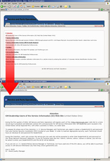
During the first quarter of 2004, GM Service and Parts Operations will
migrate users of the http://service.gm.com web site to a more secure
log-in procedure and eliminate common IDs and passwords for GM Service
Information (SI) (fig. 1). GM dealership
users located in the United States will be affected first, with other
customers to follow at a later date.
Access for U.S. Service Managers and Technicians
To prepare for phase one of the transition, U.S. service managers and
technicians are urged to obtain a DealerWorld ID and password from your
Partner Security Coordinator (PSC) located at your dealership (fig.
2 and 3). In order to maintain appropriate security, each technician
should have an individual ID and password for DealerWorld.
During the transition, users who access the service.gm.com
web site will be prompted to enter their DealerWorld ID and password
at the “Enter Network Password” dialog box.
TIP: If your
ID presently looks like this -- si2kncr, si2kwwr, si2kscr, si2kser or
si2kner -- you will now be asked to enter your DealerWorld ID. The old
ID will be deleted.
How to Purchase Access
If you are not a U.S. General Motors service manager or technician,
but have used one of the IDs above, you will be able to purchase access
to GM Service Information (SI) from http://www.gmtechinfo.com.
-
Thanks toBob Savo and Lisa Scott |
figure
1 |
figure
2-3 |
| return
to Table of Contents |
|
|
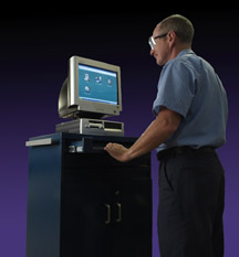
| Transitioning
from Windows 98 To Windows 2000/XP |
GM Service Operations will end testing support for the following PC
operating systems:
- Windows 98 Second Edition
- Windows Millennium
- Windows NT 4.0
End of support will be effective January 15, 2004. This end of support
follows the GM ACCESS end of support announcement for Windows 98SE in
the GM Messenger announcement VSG20030967.
What End Of Support Means. GM Service Operations discontinues
validation testing of current and future software releases on these
operating systems. Also, Techline Customer Support Center (TCSC) 1.888.337.1010
prompt 3 will provide only limited troubleshooting support on issues
that may be operating system related.
Microsoft Ends Support. With Microsoft no longer supporting
these operating systems, updates for virus protection, fixes and enhancements
will no longer be available.
GM ACCESS Network Administration / Management. With
the GMA 2 servers deployed to all NAO dealerships, network administration
for Techline clients will become more complex, as individual user identification
/ password (ID / PW) credentials must be issued rather than the previous
'generic' Techuser account. (See the accompanying article for more information
on individual ID / PWs.) Supporting this administratively at the dealership
and GM ACCESS levels on Windows 98SE clients is cumbersome and not endorsed
by GM ACCESS.
Technology Lifecycle. PCs that are running Windows
98SE and Millennium are commonly Pentium II and Pentium III systems
in their 3rd and 4th year of effective life cycle. Many of these systems
will not have adequate processor speed or memory to run Windows XP or
Windows 2000 efficiently. In addition, Techline applications function
more efficiently on Windows XP and Windows 2000.
The following specification is the minimum PC configuration:
- Intel Pentium III 600 MHz
- 128 MB SDRAM
- 16 MB DRAM Video Memory
- 16x CDROM
- Windows 2000 Professional/Internet Explorer 6.0
- Windows XP Professional/Internet Explorer 6.0
Systems that do not meet or exceed this minimum specification should
NOT be considered for upgrade but rather replaced.
TIP: It is recommended
to use a full operating system installation rather than an upgrade.
Use of an upgrade may affect proper functionality of SI.
Refer to http://service.gm.com for
current Techline hardware specifications or contact the Techline Customer
Support Center (TCSC) for assistance in selecting the correct Techline
PC.
TIP: If you attend
NADA 2004, stop by the GMSO exhibit for more details.
-
Thanks to Bob Savo and Mike Waszczenko |
|
|
|
| Labor
Operation for Reprogramming |
When
you program a module under warranty, bulletin 02-06-04-057C reminds
you to use the labor operation that most accurately reflects the module
that is being programmed.
GM uses warranty information to make decisions on which components require
engineering changes to assure that customer needs are being met.
Refer to the bulletin for details, including labor times. The bulletin
also explains how to determine the correct code for exceptions. The
accompanying table is a summary.
- Thanks to Marty Case
Module
Being Reprogrammed |
Labor
Operation Number |
Engine
Control Module |
J6354 |
Body
Control Module |
N4808 |
Transmission
Control Module |
K5364 |
Transfer
Case Control Module |
N8521* |
HVAC
Module |
D4707* |
Driver
or Passenger Door Module |
N8520* |
Instrument
Panel Cluster Module |
N4199 |
* Do not apply to
C4500-C8500 vehicles |
| |
return to Table of Contents |
| |
| GMLAN
Update |
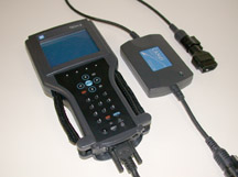
This
is an update on the GMLAN (Local Area Network) article which first appeared
in the March 2003 TechLink. Since then, more GM vehicles have begun
utilizing GMLAN data communication systems. These vehicles require the
use of a CANdi (Controller Area Network diagnostic interface) module
for Tech 2 communications (fig. 4). At
present, the 2004 Cadillac XLR and CTS, Chevrolet Malibu, Saturn ION,
and Buick Rendezvous with LY7 engine all use GMLAN for a portion of
their data communications. These vehicles continue to use Class 2 communications
along with GMLAN.
During Tech 2 communications with a GMLAN equipped vehicle, the CANdi
module must be installed in the data cable between the Tech 2 and the
DLC. Class 2 data will pass through the CANdi module, so it can stay
in place when communicating with GMLAN or Class 2 data. Failure to install
the CANdi module can result in communication errors with the Tech 2.
These errors may lead to misdiagnosis, or unnecessary calls to the Technical
Assistance Center.
TIP: Perform
the Tech 2 functionality test before using the CANdi module for the
first time. This will assure all of the circuits used by the CANdi module
are functioning properly. The March 2003 issue of TechLink explains
this funtionality test. For further support, call the Techline Customer
Support Center at 1.800.828.6860 (1.800.503.3222 in French).
-
Thanks to Russ Gilbert |
figure
4
|
| |
| return
to Table of Contents |
|
| ABS
or TCS Light On |
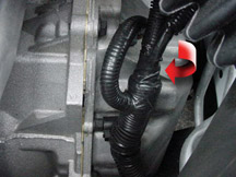
If
the ABS or TCS light is on intermittently in a 2003-04 Buick Regal,
check the electronic brake module harness (EBTCM). If it is positioned
wrong, it may rub on the transaxle rib (fig. 5).
Make the necessary repairs to the wiring, and reroute the harness away
from the rib.
-
Thanks to Wayne Zigler |
figure
5 |
| return
to Table of Contents |
|
| Tire
Rotation Additional Information |
An
article in the October TechLink referred to tire rotation on the 2004
Cadillac SRX. It pointed out that, because of dissimilar sizes, tires
cannot be rotated between front and rear.
TIP: Side to
side rotation, while technically possible, is not needed. |
| |
| return
to Table of Contents |
|
| Vehicle
Data Recorder |
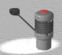
A
completely redesigned version of the J-42598 Vehicle Data Recorder (VDR)
has just been released (fig. 6).
The most important reason for revising the VDR is that GM has introduced
the GMLAN communication system (see TechLink March 2003). The earlier
VDR, which was Class 2 based, could not communicate with the new GMLAN
vehicles. So a redesign was necessary. The new VDR will communicate
with both Class 2 and GMLAN vehicles without need for any adapters.
Do not discard your current VDR. It will still be supported by the same
software release as the new VDR CAN+. The old VDR will be supported
as long as Class 2 vehicles are available.
As before, the VDR has the same snapshot recording capabilities as the
Tech 2. It’s designed to capture data during an intermittent driveability
condition, while the customer drives the vehicle. The VDR can be programmed
to be triggered by specific conditions, or it can be triggered by the
driver pressing the lighted button on the tool.
The VDR has the capacity to receive and record four 30-second snapshots.
If a fifth recording is attempted, the oldest one is overwritten.
The VDR is now shaped like a beverage container, so it fits into the
cupholder included in most new vehicles. When not in use, the data cable
can be wrapped around the VDR for convenient storage.
The VDR is rugged and able to withstand contact with engine and transmission
oil, coolant, brake fluid, and degreasers found in service areas.
As before, you will be able to program the VDR using your Techline terminal,
which must have the latest program installed from the CD Revision 9.0
which comes with the tool. You will also use your Techline terminal
to download, display, store and print the data recorded by the VDR.
And finally, the new VDR is capable of recording data from not only
the powertrain and transmission modules but also from chassis modules
as well. Additional chassis coverage will be available in future software
releases.
-
Thanks to Mike Banar |
figure
6 |
| |
|
return
to Table of Contents |
|
| Steering
Wheel SIR Inflator Module (Air Bag) Replacement Clarification |
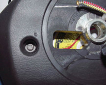
This
information applies to the Chevrolet Venture (U van) from 1997 through
2001. For these model years, the air bag is retained to the steering
wheel with Torx bolts.
To remove the air bag, remove the bolts from the back side of the steering
wheel (fig. 7). Temporarily remove the
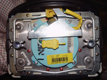
clips from the back of the air bag, to free the pins from the air bag.
Install the clips on the air bag, where they came from (fig.
8).
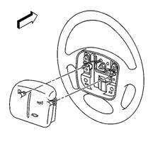
To install the air bag, first install the pins to the steering wheel
with the Torx bolts. After the pins are installed to the steering wheel,
simply push the air bag onto the wheel until the clips snap into place
on the pins (fig. 9).
TIP: For 2002
and later, the Chevrolet Venture uses an air bag retained by clips,
the same as Oldsmobile and Pontiac models. This type of air bag requires
special tool J-44298 to release the clips, following SI procedures.
- Thanks to Bill Trainor and Tom Gahl |
figure
7 |
figure
8 |
figure
9 |
| return
to Table of Contents |
|
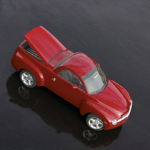
| Chevrolet
SSR Pre-Delivery |
Refer
to bulletin 03-00-89-035 for the complete pre-delivery story on the
new Chevrolet SSR (fig. 10 and 11). Performing
a quality pre-delivery inspection is one of the most important functions
your dealership can do for the customer. A quality PDI is essential
to improving a customer’s perception of your dealership and increasing
satisfaction with the new vehicle. Here are highlights from the bulletin
as well as service tips to help understand some of this vehicle’s
unique features.
Wheels and Tires
Set the tire pressure to 30psi (207 kPa) to achieve the intended vehicle
ride and handling characteristics for normal driving.
TIP: The Owner’s
Manual states that if the vehicle is driven at high speeds of 100 mph
(160 km/h) or higher, where it is legal, set the cold inflation pressure
to the maximum inflation pressure shown on the tire sidewall, or to
35 psi (244 kPa), whichever is lower.
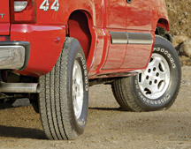
To avoid damage to the silver-painted flangeless aluminum wheels, hand
wash the vehicle or use a rail-free car wash.
TIP: Also be
careful not to damage the wheels on the side rails of a flat-bed hauler
when transporting the SSR.
Because the wheels are different sizes (19 inches in front and 20 inches
in rear) the tires should not be rotated. Each tire and wheel should
be used only in the position it is in.
TIP: The SSR
has a tire inflation kit; no spare tire is included.
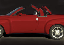
Miscellaneous Prep Tips
Cycle the retractable hard top to ensure proper operation (fig.
12). The cargo cover must be closed before the top will operate.
Check SI for diagnosis and repair if the top does not operate properly.
Driver Information Center messages and DTCs are useful in diagnosing
improper operation.
In the Driver’s Information Center, reset the average fuel economy,
range, and trip odometer.
Center the exhaust tips if necessary.
Install loose-shipped parts and RPAs.
- Floor mats
- Spare keys
- Owner’s manual and Getting to Know guide
- Top release tool in the pen holder loop of the owner’s manual
portfolio
- Front license plate option VK3 if necessary
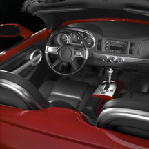
TIP: You must
use tool J-45999 to remove the cupholder or the coinholder. Using any
other tool will result in damage to the right knee bolster trim.
Remote Keyless Entry
The Tech 2 must be used for this procedure. When “building”
the vehicle, specify 2003 Pontiac Grand Am. Then follow SI procedures
to complete the process.
HVAC
When the mode knob is turned all the way clockwise to the full defrost
position (yellow), the fan runs at the highest speed and the temperature
is at max. This is regardless of where the other knobs are set. When
the mode knob is moved from max defrost, operation returns to normal.
The fan speed can be changed manually in the max defrost mode as well.
Tailgate and Cargo Cover Operation
To open the tailgate, open the cargo cover using the remote keyless
entry transmitter or the cargo cover release button in the glovebox.
Pull up on the handle inside and lower the tailgate.
To close the tailgate, close the cargo cover before closing the tailgate.
Push the tailgate upward to return it to its upright, latched position.
Push and pull on the tailgate to make sure it is secure.
-
Thanks to Dan Oden
|
figure
10 |
figure
11 |
figure
12
|
|
return
to Table of Contents |
|
| Sit-N-Lift™
Power Seat Now Available |
With the Sit-N-Lift power seat, GM becomes the only automotive manufacturer
in the U.S. to offer a fully motorized, rotating lift-and-lower passenger
seat (fig. 13).
The innovative Sit-N-Lift power seat is available on extended wheelbase
Chevrolet Venture, Pontiac Montana and Oldsmobile Silhouette minivans
with second row captain’s chairs. It’s a regular production
accessory (RPA), installed at the dealership.
TIP: The equipment
is shipped from the factory separately from the vehicle. It is identified
with the vehicle’s VIN. Installation instructions are shipped
with the equipment, along with an owner's manual supplement that covers
operation of the Sit-N-Lift Power Seat.
TIP: Service
information for the Sit-N-Lift components is available in SI under Body
- Seats.
More information on Sit-N-Lift and GM Mobility is available at http://www.gmmobility.com.
- Thanks to Bill Trainor and Bob Jubenville |
 figure
13
figure
13 |
|
return
to Table of Contents |
|
| Fuel
Gauge Conditions |
Bulletin
03-08-49-014A contains revised information for fuel gauge conditions
on 2001-03 Blazers and Jimmys, and 2001 Envoys. The conditions are model
year related.
TIP: For 2001-02
models, the information applies to 4-door models only.
A new service calibration was released on TIS2000, version 9.0 or later.
Use this calibration to reprogram the PCM.
TIP: If the cluster
part number is required, you can obtain it using the Tech 2. DO NOT
remove the cluster.
- Thanks to Dan Oden |
| |
return
to Table of Contents |
|
| Quadrasteer™
Service Update |
Here
are some service tips for the Quadrasteer system (fig.
14). For complete information, refer to the appropriate sections
of SI.
Understanding the Features of Normal Quadrasteer Operation
- Rear steering angle is limited to 5° in Park (with no vehicle
speed). Once the vehicle attains forward speed, the system is capable
of 12°.
- Rear steering angle is limited to 5° when driving in Reverse
- The system defaults to 2WS if in Neutral for more than 4 seconds.
The 2WS mode light will illuminate and the light for the previously
selected mode will flash. When shifted out of Neutral, the system will
automatically return to the previously selected mode.
- Quadrasteer will change modes only when the steering wheel passes
through center. Until that occurs, the indicator for the requested mode
will flash. (2003 and newer models will switch modes immediately if
speed is 0).
Vehicle Requirements for Quadrasteer to Operate
- Engine must be running
- Generator / Charging system must be functional. If a fault is detected
by the Generator / Charging system, the Quadrasteer system will become
inoperable to minimize battery drain.
- System voltage must be within a 9 – 16 volt range.
- System voltage is supplied by one high-current connection, one low-current
connection, and one ignition line.
- Valid vehicle speed information from the PCM (hard-wired and Class
2 message) and ABS (Class 2 message) must all correlate.
- Valid hand wheel steering shaft position information must be received.
Analog information from the Truck Body Controller (TBC) Body Control
Module (BCM) via Class 2 and digital information is obtained from phase
A, phase B, and Marker pulse of the position sensor wired directly to
the Quadrasteer control module.
- Valid signals from rear position sensor.
Most Common Mis-Diagnosed Quadrasteer Issues
- Quadrasteer does not operate and all three mode lights illuminated
solidly
Control module needs to be programmed (‘03 model year and above)
and/or needs Tech 2 alignment to be performed. No Class 2 information
is available until the module is programmed.
- Quadrasteer does not operate and mode lights are blinking.
The vehicle may be in Neutral. Quadrasteer will return to normal operation
when shifted out of Neutral and steered through straight ahead.
- C0550 DTC -- internal controller fault
May be caused by a loose 125 amp Mega-fuse, shorted Lat / Yaw combo
sensor, or water intrusion into rear position sensor.
- C0522 DTC and/or C0532 DTC – Rear Wheel Sensor and Rear
Sensor to Hall Comparison
May be caused by shorted Lat / Yaw combo sensor, or water intrusion
into rear position sensor.
- C0455 DTC – Handwheel Position Sensor (HWPS)
May be caused by improper terminal tension at HWPS connector, loose
or damaged ground at circuit G203 (‘03 model year and above),
or damaged harness between C201 and HWPS connector.
- Quadrasteer inoperable with no DTCs present
May be caused by missing required vehicle signals such as Ignition (541),
Batt2 (2640), Engine Run message (Class 2) or faulted Charging System.
See Vehicle Requirements for Quadrasteer Operation above.
TIP: Clearing
History DTCs from the controller is NOT required to restore normal operation
during troubleshooting. Please leave codes stored in the module. This
will aid in root cause analysis.
- Thanks to Steve Love |
figure
14 |
| |
| |
| return
to Table of Contents |
|
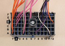
Damaged
Electrical Terminal |
Some
2001-04 Buick Century and Regal models may have a combination of the following
intermittent conditions:
- Inoperative IP cluster
- Inoperative SES, TCS ABS lights
- Inoperative air bag light
- Inoperative power windows
- Inoperative sunroof
- Inoperative radio
- Inoperative turn signals
- No crank
- Security light on
- BTSI stuck in PARK (2003-04 only)
- DTCs: U1000, U1016, B1422, B2957, B2958, and possibly others
These may be caused by a damaged terminal in the Underhood Accessory Wiring
Junction Block (also sometimes called the Underhood Bussed Electrical
Center or UBEC). This terminal provides voltage from the IGN 1 30-amp
fuse to nine circuits in the vehicle’s interior.
If the condition is intermittent, and normal diagnosis does not lead to
a conclusive failure mode, perform these steps.
Remove the Underhood Accessory Wiring Junction Block from the bracket
at the right strut tower. Loosen the bolt in the center of connector C2
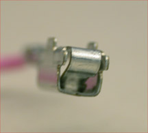
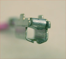
and pull the connector loose. Check terminal D2 for damage (fig.
15). A good terminal is shown in figure 16
and a damaged one in figure 17.
If the terminal is damaged, obtain a replacement (p/n 12110844) from tray
4 of the J-38125 Terminal Repair Kit. Install it according to proper SI
procedures.
-
Thanks to Wayne Zigler |
figure
15 |
figure
16 |
figure
17 |
return
to Table of Contents |
|
| Product
Feedback Processes |
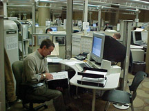
In
today’s competitive market, vehicle quality is a key factor in
retaining customers and creating customer enthusiasm for our products.
Because dealership personnel are in contact with customers and vehicles
on a daily basis, you’re in an excellent position to be up to
date about current concerns. GM wants to hear what you have to say (fig.
18).
That’s why an important part of GM’s continuous quality
improvement process is collecting information from the field. Engineers
use the data collected to decide how to improve product quality and
modify assembly plant procedures.
Another spin-off is that the information can be distributed to the field
in the form of service bulletins, VME messages, TechLink articles and
the Fix It Right the First Time information (see page 8 of each issue
of TechLink).
When you in the field and engineers at GM are able to work together
to share information, quickly respond to customer concerns and address
product quality issues, everyone wins. Particularly the customers, which
is directly reflected in CSI, and other consumer surveys.
Here’s a brief summary of the various processes presently in use.
These processes were developed with an eye toward creating minimum interference
with workflow in your dealership. We appreciate the effort your dealership
takes to help us in this ongoing quest to maximize the quality of our
products.
General Motors Sentinel Dealers -- These are specific
dealers in key geographic locations across the county who supply Repair
Order information electronically from their dealerships on a daily basis.
Part Restrictions -- In this process, Product Quality
Center and TAC restrict a particular part number or labor operation.
Before proceeding, the dealerships must contact either TAC or PQC, who
collect specific information on the issue. Even if your dealership has
the part in stock, the PQC should be contacted first. These restrictions
can last from a few weeks to 90 days or more -- whatever is required
to permit Engineering to gather enough data to determine the root cause
of the issue.
We are careful not to have too many restrictions going on at one time.
But, the cost and inconvenience of the restriction at both the dealership
level and General Motors is more than offset by the value of improved
product quality. Parts restriction has proven to be one of the most
effective sources of product information we have developed.
Action Centers -- The Action Centers are set up to
gather information for the assembly plant of a new product. The Action
Center takes phone calls from dealers that need help with one of these
new products. The information is then directed to the assembly plant
and improvements are made very rapidly.
Field Engineering Investigation Process -- In this
process, Engineering uses the VIS system to explain what they are looking
for. The Service Advisor prints out the instructions in VIS for the
technician. The technician is requested to contact TAC after following
the directions. A specific labor operation is provided to pay the technician
for this effort in helping the Field Engineering Investigation process.
PQC will process this specific labor operation with prior approval so
the dealership gets paid for the activity.
Warranty Parts Center Process -- All parts of a new
vehicle are returned to the WPC for six months after the vehicle is
launched. In addition, Engineering and Brand Quality can request the
return of a specific part number when the part is replaced on a warranty
claim. Returned parts are analyzed to determine root causes for why
the parts were replaced, and improvements are pursued.
The Field Service VME System -- This provides two-way
voice communication on product issues between GM Service and the dealers.
In the normal course of vehicle repair, if you come across something
that you think will help us improve the repair and quality of our vehicles,
you can use the Field VME Product Feedback system to let us know.
-
Thanks to Jim Colyer, Melissa Suhy, Jack Pantaleo and Ann Briedis |
figure
18 |
| |
| |
|
return
to Table of Contents |
|
| Transaxle
Electrical Connector |
Be
on the lookout for bulletin 02-07-30-022B, which is being re-issued to
include 2004 model year vehicles.
The bulletin applies to numerous carlines which use the 4T65-E, 4T40-E
or 4T45-E transaxles.
Some customers may comment that the SES lamp is illuminated, accompanied
by extremely harsh shifts. The conditions may be caused by an intermittent
connection at the transaxle 20-way connector (fig.
19).
The bulletin lists six potential causes:
- harness stretched tight
- terminals not fully seated
- male terminals bent
- female terminals loose
- terminals insufficiently crimped to wire
- connector not properly seated and locked
Perform an inspection and make the necessary repairs.
-
Thanks to Bob Martin |
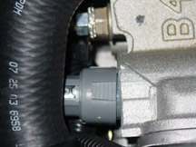
figure
19 |
| |
| return
to Table of Contents |
|
| A/C
Compressor Diagnostic Tips |
The information here deals with two conditions that appear to be contradictory.
In the first case, compressors may have been replaced unnecessarily, and
in the second case, compressors may need to be replaced. Here are the
details.
1993-Present Cars and Trucks
Refer to bulletin 01-01-38-013A, which provides information to consider
before replacing an A/C compressor for noise, vibration or insufficient
cooling. Only highlights are given here.
The bulletin lists numerous system conditions (other than the compressor)
that can cause these symptoms. High on the list is the state of refrigerant
charge, either too low or too high. Others include loose attachment hardware,
worn drive belt, grounded refrigerant lines, improper or insufficient
airflow, contamination, and improper oil charge.
TIP: Perform a
thorough visual inspection before performing tests or repairs.
TIP: Use the ACR
2000 Tool to recover and weigh the refrigerant charge to help accurately
diagnose a charge level condition.
If careful diagnosis legitimately leads to compressor replacement, be
sure to follow the bulletin guidelines to determine which of the following
may be appropriate: oil balance, suction screen filter, flushing, addition
of fluorescent dye.
TIP: Bulletin 01-01-38-006B
provides additional information on flushing procedures.
G-Vans and C/K Trucks from January 2002 through April 2003
All of these vehicles use a Denso compressor (fig.
20). Customers with these vehicles may comment on underhood noises
or insufficient cooling.
TIP: If proper
diagnosis pinpoints the compressor as the cause, replacement is the appropriate
repair. Compressors built between the dates listed may be more susceptible
to these conditions.
TIP: A redesign
in April 2003 addressed the reed valve and retainer gasket. Compressors
built after April 2003 are redesigned, revalidated and significantly improved.
These can be easily identified: the serial number begins with 5E.
Part Numbers for Redesigned Compressor
| C/K |
15100337
/ 338 / 339 / 340 |
| G Van |
15106396 /
397 |
The symptoms may be caused by a condition called “liquid slugging.”
In a properly operating A/C system, the refrigerant may be either liquid
or gas, depending on where it is in the system. At the compressor, the
refrigerant is supposed to be gaseous. If liquid refrigerant enters
the compressor, slugging occurs. Because liquid is not compressible,
pressures become extremely high and damage can occur to the reed valves
and retainer gasket.
TIP: The A/C
systems on large vehicles such as vans and utilities contain a larger
amount of refrigerant, and the lines have a greater number of bends,
both of which provide extra opportunities for liquid refrigerant to
return to the compressor. Also, on some of these vehicles, the A/C compressor
is low-mounted, which increases the opportunity for liquid to pool.
-
Thanks to Steve Haar and Saundra Massingille
|
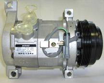
figure
20 |
| return
to Table of Contents |
|
| Loud
Pop or Snap Noise From I/P in Hot Ambient Temperatures |
On
some 2001-03 Chevrolet Impalas and Monte Carlos, a loud popping or snapping
noise may occur at the windshield or I/P pad area. It is often described
as sounding similar to a stone hitting the windshield.
The noise most often occurs shortly into a drive cycle after the A/C begins
cooling the interior, after the vehicle has been sitting in high ambient
temperatures, usually above 90° F (32° C). The noise originates
from the metal plates riveted to the underside of the Upper I/P Pad over
the Instrument Cluster and Passenger Side Airbag.
Once the condition is confirmed, replace the Upper I/P Pad with a new
part from GMSPO. The new pad has eliminated the plate over the Instrument
Cluster and should correct most ocurrences of this condition. Additional
Field Product Reports regarding the successful repair of vehicles using
this procedure would be appreciated.
-
Thanks to Phil Race |
| |
| return
to Table of Contents |
|
| Flywheel
Bolt Holes |
When
replacing the flywheel on a GEN III V-8, you may notice the bolt holes
for the crankshaft in the replacement flywheel are larger than the holes
in the original part.
The original part was superseded. The new flywheel has slightly larger
bolt holes. New bolts with washers have a 22.3 mm conical design and will
provide sufficient clamp load to install the new flywheel. The new bolts
part number 12563533 and flywheel are applicable only on LQ4 engines or
LR4 engines for 1999 and 2000. Install the flywheel using the appropriate
Service Information procedure.
-
Thanks to Sean Garrison |
| |
| return
to Table of Contents |
|
| Tire
Pressure Monitor System Message Displayed On DIC |
On
some 2004 Pontiac Grand Prix models, a customer may comment that there
is a Check Tire Pressure message on the DIC. There may not be any DTCs
or visible defects and no malfunction can be identified in the system.
Inspect the rear wheel speed sensor harnesses 5-10 inches (12-25 cm) inboard
of the suspension knuckles for the presence of either an orange or white
tape label on the left rear harness. If it is on the left harness, the
sensor is installed incorrectly and should be swapped with the right side,
where it belongs. Both rear wheel speed sensors share the same connector
and have harnesses of simliar length.
-
Thanks to Phil Race |
| |
| return
to Table of Contents |
|
| Supplemental
Brake Assist Noisy and May Run Continuously |
On
some 2003 C/K vehicles, the Supplemental Brake Assist (SBA) motor is noisy
and runs when the brake pedal is depressed and may run continuously when
the brake pedal is released.
Use P/N 89040236 to correct this customer concern.
-
Thanks to Dana Evanoff
|
| return
to Table of Contents |
|
| Poor
or No HVAC Heat |
Owners
of some 2004 Cadillac CTS and SRX models may experience poor or no HVAC
heat.
Check the thermostat housing (P/N 12573977) for casting flashing. Remove
the flashing from the thermostat housing. If the material cannot be removed
without damaging the housing, replace the housing.
- Thanks to Duane Raymond
|
| return
to Table of Contents |
|
 Car Issues – Fix It Right The First Time
 |
Model
Year(s) |
Vehicle
Line(s) --
Condition |
Do
This |
Don’t
Do This |
Reference
Information / Bulletin |
2000-2004 |
Cavalier/Sunfire
-- Grinding Noise on Clutch Apply. Very low mileage |
Replace
clutch hydraulic line. |
Don’t
replace clutch/bearing |
02-07-31-003A |
2003-2004 |
Vibe
– Normal Exhaust Odor |
Provide
a copy of the service bulletin to the customer. |
Don’t
replace the catalytic converter |
06-05-006 |
1997-2004 |
Grand
Am / Alero / Malibu – Brake pulsation |
Turn
rotor and use brake align procedure |
Don’t
replace rotors for pulsation |
00-05-23-002
01-05-23-001 Know How 15040.01B) |
2001-2003 |
Venture
/ Montana / Silhouette/Rendezvous/ Aztek – Rattle or Buzz
from Exhaust System |
Install
clamp |
Don’t
replace catalytic converter |
03-06-05-003
dated 01/28/03 |
2004 |
Grand
Prix with Monsoon System -- Speaker Buzz |
Re-Pin
Speaker wires in the IP fuse panel connector |
Don’t
replace the Speaker, Amplifier or Radio |
03-08-44-015 |
2000-2004 |
Impala
/ Monte Carlo -- Condensation in Headlamp |
Normal
when limited to fog or fine mist appearance in high humidity conditions |
Don’t
replace headlamp assembly when no water droplets evident |
01-08-42-001
Sept 2000 TechLink |
2003-2004 |
CTS
– Variable Effort Steering (VES) “Service Steering
Message” DTC C1241 or C0450 |
Replace
VES solenoid only |
Don’t
replace entire steering gear |
03-02-36-001 |
2003 |
All
cars with 4T40/45E, 4T65E and 4T80E – Code P0742 |
Replace
TCC PWM
solenoid and valve asm. |
Don’t
replace transmission or valve body assembly |
02-07-30-039B
(Part numbers in bulletin have been superceded) |
2002-2004 |
All
cars with 4T40/45E and 4T65E with DTC P0716, P0717 and other misc
codes |
Disconnect,
inspect, and reconnect transaxle wiring harness at the transaxle. |
Don’t
replace input speed sensor. |
02-07-30-022B(Oct
2003)
Sept 2003 TechLink |
2004 |
L61
EcoTech 4 Cylinder 2.2L Engine |
Replace
Spark Plug Sets |
Don’t replace PCM or ignition cassettes |
03-042
Recall |
|
| return
to Table of Contents |
|
|
 Truck Issues – Fix It Right The First Time
|
Model
Year(s) |
Vehicle
Line(s) --
Condition |
Do
This |
Don’t
Do This |
Reference
Information / Bulletin |
1999-2004 |
Vehicles with HomeLink Universal Transmitter – Programming
Diagnosis |
Use
J41540 HomeLink Tester, follow SI, refer customers to owners manual |
Don’t
replace HomeLink Transceiver without validating internal fault |
01-08-97-001B |
1999-2003 |
Silverado, Sierra, Savana, Express 8600 GVW – ABS lamp on |
TIS
Version 4.0 Re-flash for code C0550 H2504 |
Don’t
replace ABS Module |
03-05-25-003 |
2003-2004 |
FullSize Pickups and Utilities – Door Trim Panel |
Remove
front door panel, then remove switch bezel retaining screw. |
Don’t
pry switch bezel out of door trim panel without first removing
retaining screws |
Service
VME
03-08-64-022 |
2003-2004 |
Fullsize
Pickups and Utilities – Servicing Wide Load Mirrors (RPO
DPF) |
Replace
individual parts as needed |
Don’t
replace complete mirror assembly |
03-08-64-028 |
2003 |
Fullsize Pickups and Utilities – Transfer Case Service Light |
Replace
encoder motor sensor and reprogram TCCM |
Don’t
replace module, encoder motor or transfer case |
03-04-21-001B |
2003 |
Fullsize
Pickups – 6.6L Diesel Engine ECM |
Follow
SI and bulletins for proper diagnostics for P0181, refer to the
Owner’s Manual (block heater and front cover) |
Don’t
replace ECM unless diagnostics confirm need to replace |
02-06-04-048,
03-06-04-021, 02-06-04-058 and parts restriction |
2002-2003 |
TrailBlazer,
Envoy, Bravada -- Squeak Rub/Scrub Type Noise in Steering Column |
Lubricate
and remove material per bulletin |
Don’t
replace upper or lower intermediate shaft |
02-02-35-006A |
2002-2004 |
TrailBlazer,
Envoy, Bravada, Rainier – Tail Lamp Socket Circuit Board |
Replace
both tail lamp circuit boards |
Don’t
replace complete assembly |
Service
VME 9/22/03
03-08-42-006A |
2002-2003 |
TrailBlazer,
Envoy, Bravada – Windshield Washer Nozzle |
Replace
windshield washer nozzle |
Don’t
replace complete cowl assembly |
Service
VME 06/25/2002 |
2002-2004 |
TrailBlazer,
TrailBlazer EXT – Wavy Front Fascia |
Repair
fascia with Dual Lock |
Don’t
replace front fascia |
02-08-62-004 |
| 2002-2004 |
TrailBlazer,
Envoy, Bravada – Mirror Erratic Return |
Replace
mirror actuator and reprogram module |
Don’t
replace outside mirror assembly |
02-08-64-008
02-08-64-021 |
|
| return
to Table of Contents |
|
|
| Know-How
Broadcasts for January |
| |
 |
| Know-How
Broadcasts for January |
| 10280.01D
Emerging Issues |
January
15, 2004 |
9:00
AM, 12:30 PM,
3:30 PM
Eastern Time |
| 10280.13D
Brakes - Town Hall |
January
29, 2004 |
9:00
AM, 12:30 PM,
3:30 PM
Eastern Time |
| -
Thanks to Tracy Timmerman |
|
|
| return
to Table of Contents |
| |
