|
 |
Note: Clicking
on any picture or illustration will open a larger version of that art.
|
|
Brake
Service |
Part
1 -- Background, Measuring, and Cleaning
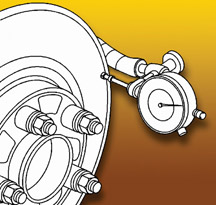
Earlier this year, bulletin 00-05-22-002D was released for the purpose
of updating and centralizing all of GM’s standard brake service
procedures and policy guidelines for brake rotor and brake pad service
and wear (fig. 1). If you haven’t already done so, refer to this
bulletin before performing your next GM brake service.
Over the next few months, TechLink will provide several brake articles
featuring information from this bulletin, and in some cases expanding
on it. You must observe the practices contained in the bulletin and
in SI.
WHAT CONSTITUTES A SUCCESSFUL BRAKE SERVICE?
Five steps must be performed to complete a successful brake service.
1. Measure and document rotor thickness -- specifications in SI
2. Clean hub, rotor and wheel mating surfaces
3. Perform proper rotor refinish and documentation
4. Measure, document and correct lateral run out (LRO)
5. Reassemble with proper torque and document final rotor thickness
NECESSARY AND UNNECESSARY BRAKE SERVICE
Rotors
Contrary to general understanding, many rotors can be resurfaced rather
than replaced. Rotors should not be replaced for “lot rot.” In
a recent study, low mileage rotors were cleaned up with minimum of
77% of life remaining.
Rotors should not be replaced for pulsation. In a recent study, rotors
under 12,000 miles (19,000 km) were cleaned up with minimum of 70%
of life remaining.
TIP: Replacement for rotor flaking should be handled on a case by case
basis.
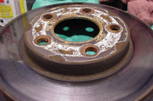
Pads
Pads should not be replaced unless excessively worn, contaminated or
damaged (fig 2).
TIP: If replacement is necessary, always replace disc brake pads in
axle sets using OEM pads if repaired under warranty.
Brake pad replacement necessary under warranty:
- Substantial premature pad wear (see specific pad specifications/gaps/wear
sensor information in SI).
- Damaged pad friction surfaces (cracks, fractures, separation from
mounting plates or other issues that could impair brake performance).
- Uneven vehicle side-to-side/premature pad wear due to caliper issue
requiring repair issue.
- Pad material contamination (oil, grease, etc.)
TIP: If pad replacement for one of these causes is performed, also
perform and document repair to correct the cause of the concern.
Brake pad replacement unnecessary under warranty:
- Pads generally should not be replaced for noise concerns, unless
specifically directed by a Bulletin addressing customer’s concern
- Pads should not be replaced just because rotors are being serviced.
DEFINITIONS OF CORROSION
Corrosion is caused by normal oxidation (rust) that is not cleaned
off of the rotor by the pad but is impacted into the rotor.
Corrosion may cause owner complaints of pulsation or noise.
Corrosion may range from very light to heavy scaling.
Light Corrosion
Rusting on the rotor braking surfaces may occur when a vehicle is not
driven for extended periods. Light surface rust is often cosmetic and
can be eliminated during a few normal driving stops.
Perform 15 moderate stops from 35-40 mph (62-75 km/h) with cooling
time between stops.
Light “Delamination”
“
Delamination” looks like a layer of paint flaking off the rotor.
This layer is composed of rust and pad material. “Delamination” is
NOT rotor surface degradation. Light flaking can normally be corrected
by refinishing the rotor.
TIP: Pads generally do not require replacement for this condition.
Heavy Corrosion / Delamination
Heavy corrosion is characterized by rust scaling and deep pitting.
This type of rotor corrosion may be too deep to machine and may require
replacement of the rotor.
WHEN SHOULD A ROTOR BE REPLACED?
A rotor should not be replaced or refinished for:
- Noise/squeal
- Cosmetic corrosion
- Routine pad replacement
- Discoloration/hard spots
A rotor should be refinished for:
Severe scoring -- depth in excess of 0.060 inch (1.5 mm).
Pulsation concerns from:
- Thickness variation in excess of 0.001 inch (0.025 mm).
- Excessive corrosion on rotor braking surfaces.
BRAKE PULSATION
Pulsation is caused by thickness variation. Thickness variation is
caused by corrosion or rotor lateral run-out.
Remember, a caliper floats in the steering knuckle. Parallel surfaces
(no thickness variation) will NOT produce brake pulsation even with
0.010 inch (0.25 mm) or more lateral run-out.
Wear-induced thickness variation usually occurs 2,000-10,000 (3,200-16,000
km) after miles after rotor service. Lateral run-out can be cut into
the rotor with an improperly maintained brake lathe.
On brake apply, a rotor with thickness variation will push the brake
pads apart resulting in hydraulic movement through brake piping to
the master cylinder and to the brake pedal.
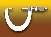
CRITICAL DIMENSIONS OF A ROTOR
Here are some details about measuring a rotor.
TIP: Thickness measurements should be done with a brake micrometer
(fig. 3), which has a pointed anvil and a deep throat.
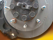
Brake Rotor Thickness
SI provides three dimensions:
- New (original)
- Minimum after machining
- Discard (fig. 4)
TIP: If you subtract the minimum thickness after refinishing from the
new thickness, the result is the amount of useful rotor life left.
TIP: Brake rotor thickness should be checked a final time just before
you put the wheel back on the vehicle.
Rotor Thickness Variation
TIP: This measurement is used when addressing brake pulsation concerns.
The rotor should be measured in at least four places in the pad contact
surface area.
SI calls for correction if the thickness variation exceeds 0.001 inch
(0.025 mm).
Brake Rotor Scoring
Scoring greater than 0.060 inch (1.5 mm) requires correction. Scoring
greater than 0.060 inch (1.5 mm) after machining requires rotor replacement.
Lateral Run-Out
Install a dial indicator, following SI procedures. Generally, the indicator
is attached to the steering knuckle, with the plunger contacting the
rotor braking surface at a right angle, and 0.25 inch (6.35 mm) from
the outer edge (fig. 5).
On most GM passenger cars, if LRO is 0.002 inch (0.050 mm) or less,
no correction is necessary. If LRO is over 0.002 inch (0.055 mm), correction
is required.
TIP: An exception is the N-car specfication of 0.0015 inch (0.038 mm).
Always check SI for specifications for the vehicle you’re working
on.
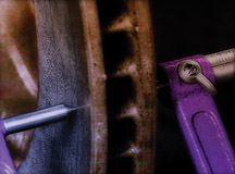
CLEANING BRAKE COMPONENTS
One of the causes of excess lateral run out is foreign material between
mating surfaces of rotor, hub, and wheel (fig.
6). These include debris,
corrosion, flaking and grease.
You need to obtain clean metal-to-metal contact to get repeatable results.
Pits aren’t so much of a problem as raised surfaces.
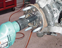
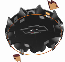
Clean rotor to hub mating surfaces using J-42450 Wheel Hub Resurfacing
Kit. The configuration of the tool permits it to fit over the mounting
stud, to remove corrosion that cannot be reached by other methods (filg
7).
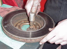
And, 80-grit abrasive discs and holder are available in the J-41013
Wheel Hub Cleaning Kit. This is useful in cleaning mounting surfaces
in general (fig. 8).
FUTURE ARTICLES
Watch for future articles that will cover refinishing, LRO correction,
final measurement and final assembly tips.
- Thanks to North Central Region Service Engineers and Field Warranty Specialists |
|
figure
1 |
| |
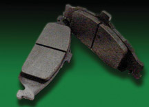
figure 2 |
| |
figure
3 |
figure
4 |
figure
5 |
figure
6 |
figure
7 |
figure
8 |
| return
to Table of Contents |
|
|
| Door
Module Programming |
This information applies to the 2005 Cadillac CTS and SRX. Although
these two vehicles share the same part number for the Door Zone
Module (DZM), their outside rearview mirrors are wired differently.
So, the production DZM is configured to identify which vehicle
it’s installed in and ensures proper mirror operation.
The service replacement DZM is defaulted to the SRX. If a service replacement
DZM is installed in a CTS, the mirrors will not operate properly.
To ensure proper mirror operation, the service replacement DZM needs
to be configured by performing the following module set up procedure.
- Connect the Tech 2 to the vehicle
- Build the vehicle (either SRX or CTS)
- Body
- Door Modules
- Select Driver Door Module or Passenger Door Module
- Set Options
- Vehicle Type
TIP: The service replacement DZM will be defaulted to SRX. Select CTS
to configure the DZM for use in a CTS.
Although the DZM does not ordinarily need programming for use in the
SRX, provision exists in the Tech 2. This will be needed in case a
module is moved from a CTS to an SRX.
SI document 1554825 and the Tech 2 special function software have been
revised to accommodate this condition.
TIP: The rear door modules are not affected by the Vehicle Type set
up because they do not operate mirrors.
EXPORT VEHICLES
The DZMs for use in export vehicles will need a VIN Relearn performed
for all four door module service parts. To learn the VIN, perform the
following procedure.
- Connect Tech 2 to vehicle
- Build the vehicle
- Body
- Door Module(s)
- Select module being replaced
- Special Functions
- Door Zone Module VIN Relearn
TIP: If the door module that is being replaced is a front door module
in a CTS that is an export, both the VIN Relearn and the Vehicle Type
set up procedures will need to be performed.
- Thanks to Tom Lawther |
| |
| |
|
|
Oil Life System Reset Procedures -- Trucks (revised) |
2004-
05 Canyon
2004- 05 Colorado
The following information clears up some confusion regarding how to reset
the Oil Life System on these trucks. There are two methods.
TIP: The Driver Information Center (DIC) is standard equipment and is
located in the lower center of the IP cluster.
Reset Stem Method
1. Turn the ignition to RUN but with the engine off.
2. Press and release the reset stem in the lower center of the IP until
the Oil Life message is displayed.
3. Once the alternating Oil Life and Reset message appears in the display,
press and hold the reset stem until several beeps sound. This confirms
the oil life system has been reset.
4. Turn the key to Lock.
If the CHANGE/OIL message comes on when you start the engine, the engine
oil life system has not reset. Repeat the procedure.
Alternate Method
1. Turn the ignition key to RUN with the engine off.
2. Fully press and release the accelerator pedal 3 times within 5 seconds.
Several beeps sound. This confirms the oil life system has been reset.
3. If the CHANGE/OIL message comes back on when you start the engine,
the engine oil life system has not reset. Repeat the procedure.
-
Thanks to Bret Marshall at Applegate Chevrolet, Flint MI and Jerry
Garfield |
|
return to Table of Contents |
|
| Water
Drip on Driver’s Foot |
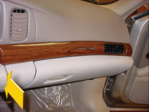
Owners
of some Cadillac CTS, STS and SRX models may experience water drips
falling on the driver’s right foot. This results from condensation
forming on the TXV assembly above the accelerator pedal.
To correct this condition, install a piece of butyl, p/n 89023394 to
the location shown in figure 9. This doubles the amount of butyl originally
installed on the TXV assembly, to further insulate it and prevent moisture
buildup.
TIP: Do not R&R or repair the HVAC module to address this condition.
-
Thanks to Chris Semanisin |
figure
9
|
| return
to Table of Contents |
|
| Top
Tier Gasoline Update |
Three
additional gasoline brands from the ConocoPhillips group have been
added to the Top Tier list. Gasolines marketed under the brands of
Conoco, Phillips, and 76 all meet the Top Tier detergent criteria.
These brands have been added to the running list on the TechLink website.
-
Thanks to Jay Dankovich
|
| return
to Table of Contents |
|
| Automatic
Climate Control |
Owners
of some 2004-05 LeSabre or Bonneville vehicles with automatic climate
control may comment that it is difficult to maintain the inside temperature
or that the blower speed stays too high.
Maintaining Temperature -- In some cases, the aspirator hose may fall
off the aspirator due to the size of the hose and the aspirator tube.
If you should encounter such a condition, remove 0.5mm of material from
the locking tab on the aspirator to allow a tighter fit (fig.
10). If
the aspirator hose is connected, the blower module will need to be reprogrammed.
Blower Speed -- A service bulletin will be released to address the high
blower speed concern.
-
Thanks to Bill Metoyer
|
figure
10
|
return
to Table of Contents
|
|
| Returnless
Fuel Systems |
Increasingly stringent evaporative emission
regulations have caused GM to introduce returnless fuel systems. In
a returnless design, no fuel is sent back to the fuel tank from the
engine. All fuel leaving the tank flows through the fuel injectors.
Returnless systems have been in production since 1998 (Trans Am, Camaro
and Corvette). A significant migration toward returnless fuel systems
began in the 2004 model year. By 2007, the majority of GM vehicles
will be converted to the returnless design.
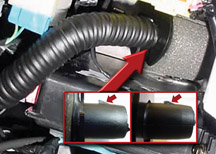
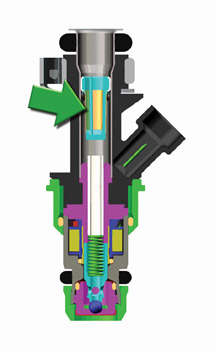
Any contamination (including rust) that is built into or forms in the
fuel line will find its way to the fuel injectors. A filter at the
inlet to the fuel injector filters out small contaminants, including
rust (fig. 11). If enough debris accumulates on the injector filter,
it will start to restrict flow. This will have a negative effect on
performance and driveabilty.
For the 2004 model year, there has been an increase in the number of
injectors returned with rust in the injector filter. The rust appears
to be coming from several sources:
- the chassis fuel line
- the crossover pipe on the Gen III fuel rail.
Both pipes are made of low-carbon steel, and the inside of the pipe
is not coated. If water gets into the fuel system, it has the potential
to rust the line.
When diagnosing driveability symptoms due to clogged fuel injectors,
follow the procedures outlined in bulletin 03-06-04-030A. If the bulletin
procedures lead to replacing an injector, inspect the removed injector
for evidence of rust contamination. If rust is plugging the fuel injector,
replace it, because a procedure for removing rust from the injector
filter has not been developed.
If rust remains in the fuel line, there is a chance that the injector
filter will plug up again. Whenever rust is observed in an injector,
flush the fuel lines. If the fuel line cannot be completely flushed
of rust, replace it.
A small amount of rust in the fuel tank will typically not cause a
problem. The fuel filter will prevent the rust from getting to the
injectors. The capacity of the filter is large enough to keep it from
plugging up. There is also a strainer (“sock”) at the inlet
to the fuel pump. The strainer prevents contamination from getting
into the fuel pump and causing problems. However, rust in the fuel
tank is a sign that water may be in the tank. If rust is observed in
the fuel tank, empty it and flush with hot water, according to SI procedures.
-
Thanks to Matt Hamilton |
figure
11
|
|
return
to Table of Contents |
|
| CPA
Incorrectly Installed |
This
information applies to the 2004 Chevrolet Malibu, 2005 Chevrolet
Cobalt and Pontiac G6, and future applications.
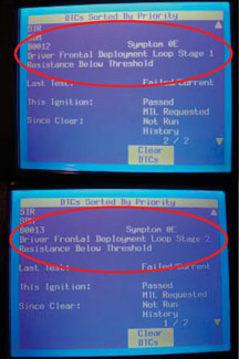
The condition begins with the SIR lamp being displayed, and codes for
driver stage 1 and stage 2 are current.
During SIR system diagnosis, the Tech 2 may display “driver frontal
deployment loop stage 1 resistance below threshold,” along with “driver
frontal deployment loop stage 2 resistance below threshold.” These
are diagnostic codes B0012 and B0013 with symptom code 0E (fig.
12).
TIP: There are two deployment loops, for stage 1 and stage 2. Each loop
has a separate circuit, but they share the same connector to the steering
wheel module coil.
If this condition exists, it may be caused by a missing or incorrectly
installed connector position assurance (CPA) in the steering wheel module
coil connector. When the CPA is removed, the shorting bars that “safe” the
driver airbag from deployment make contact to both circuits causing the
below-threshold DTCs to set.
TIP: If the connector is entirely unplugged, the Tech 2 display message
is “driver frontal deployment loop stage 1 open circuit, ” along
with “driver frontal deployment loop stage 2 open circuit.” These
are diagnostic codes B0012 and B0013 with symptom code 04.
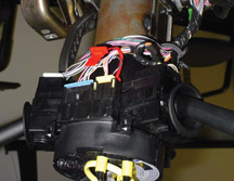
This is the connector on the top of the steering column that connects
the steering wheel module coil to the vehicle harness (fig.
13).
TIP: The CPA is bright red.
Be sure the CPA is completely plugged into the connector. Refer to SI
for the proper procedures.
TIP: Be sure to follow the instructions for disabling and enabling zone
3 in the SIR system while servicing the coil connector.
-
Thanks to Chad O’Brien |
figure
12 |
figure
13
|
| return
to Table of Contents |
|
| Engine
Coolant Heater and P0116 |
Owners
of some 2005 V8 trucks and V6 cars with the factory optional engine
coolant heater (also known as a block heater) may comment that the
heater does not work unless the air temperature is very low. This
is normal operation, intended to avoid setting a DTC P0116.
TIP: This operation is described in the owner’s manual.
The power cord has a built-in thermostat that allows operation only
if the temperature of the surrounding air is at or below 0°F (-17°C).
Also, the heating element has a low power rating to limit the amount
of heat in generates.
TIP: The air temperature thermostat is part of the cord set, not the
heater.
A DTC P0116 may set if the vehicle has an aftermarket engine block heater
installed that is more powerful than the factory-installed one and/or
that is not equipped with the thermostatic AC power cord.
Explanation of Rationality Check
The P0116 diagnostic (engine coolant temperature sensor rationality check)
can fail if the indicated coolant temperature is too high at engine startup,
after an extended time sitting without the engine running.
After a vehicle has been parked for a number of hours, the engine coolant
temperature is typically very close to ambient air temperature. This
is the definition of a cold start. After startup, OBD regulations require
that the PCM look at the rate at which the coolant temperature sensor
heats up, from a certain starting point. If the coolant temperature sensor
does not heat up according to expectations, a DTC P0116 will set.
The new heater described above has been designed to keep the coolant
temperature sensor operation outside the range that would cause a DTC
to set.
- Thanks to Jack Woodward and Guy Winohradsky |
|
| return
to Table of Contents |
|
| Roof
Rack Cross Rail Noise |
Some customers may comment about wind noise
generated by the presence of roof rack cross rails on 2005 Trailblazer/Trailblazer
EXT, GMC Envoy/Envoy XL/Envoy XUV, and Buick Rainier. The disturbance
becomes more noticeable if the cross rails are placed in positions
over the driver and passenger seating areas.
The optimal locations of the cross rails to minimize wind disturbance
are:
- front cross rail in line with the rear edge of the rear door
- rear cross rail 2 inches (5 cm) forward of the rear edge of the side
rail.
Cross rails will be placed in these locations in production on vehicles
ordered with them.
TIP: Roof rack cross rails for the GMC XUV are a Regular Production
Accessory, and will be received at your dealership separately for your
installation before delivery. Use these cross rail positions when roof
rack cross rails are installed during predelivery inspection.
- Thanks to BJ Lackey |
| |
|
return
to Table of Contents |
|
| Squeaks
and Rattles |
Owners of some Buick LeSabres may encounter
noises. GM’s Squeak and Rattle Task Force has identified the
following areas.
Instrument Panel Squeak -- Applying clear plastic tape or equivalent
between the trim panels will eliminate the noise (fig.
14).
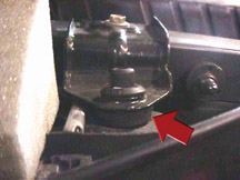
Under-Hood Clunking Noise -- This noise may be caused by excessive
clearance between the radiator hold down retainer and bushing. To correct
this condition, split another bushing and install to eliminate the
excessive clearance (fig. 15).
-
Thanks to Bill Metoyer
|
figure
14 |
| 
figure
15
|
|
return
to Table of Contents |
|
| AIR
Pump Ingesting Water |
Owners
of some 2000-04 DeVilles may comment that the MIL is being illuminated,
accompanied by the following:
- DTC P0410 is set
- evidence of water in the AIR pump
- pump shorted or seized.
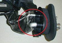
This condition may be due to water being ingested at the AIR pump inlet
hose, causing the pump to short out or seize up. A new inlet hose p/n
25768965 has been developed and released to repair this condition.
Refer to bulletin 02-06-04-024A for details.
- Thanks to Bill Denton |
|
|
| return
to Table of Contents |
|
| Master
Cylinder O-Ring |
Owners
of some 2005 Sierra or Silverado 1500 trucks may comment that they
have a Service Engine Soon light illuminated. DTC code P0171 and/or
P0174 (Lean Fuel Trim) may be set.
The cause may be a damaged or missing seal (O-ring) between the master
cylinder and the brake booster. At idle, the vacuum leak may be audible.
TIP: Because the engine generates sufficient vacuum to overcome a leak
at the seal, the driver likely won’t notice any effect on braking
performance.
TIP: Here’s how to diagnose for a leak at the seal. On your Tech
2, observe the fuel trim numbers. Unplug the vacuum hose from the booster
and plug off the vacuum hose with your thumb. If the numbers change,
there is a leak at the seal.
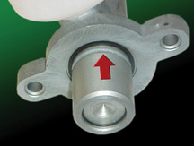
If the seal is missing or damaged, replace the seal (p/n 89059131). When
installing the master cylinder, hold the master cylinder flush to the
brake booster and torque the nuts to 36 Nm (27 lb ft).
TIP: Be sure the O-ring is against the master cylinder, not in the groove
(fig. 16).
TIP: If the booster is being replaced, be aware that the new booster
doesn’t come an O-ring, which must be obtained separately.
- Thanks to Steve Love |
| 
figure
16 |
| return
to Table of Contents |
|
| Steering
Gear Noise |
This
information applies to 2004 Pontiac Grand Prix. Some owners may comment
about a click/tick/pop noise that occurs while turning the steering
wheel when the vehicle is stopped or moving very slowly.
This condition is covered by bulletin 03-02-32-048A, which explains how
to install a new two-piece sleeve and spacer to the steering gear mounts.
TIP: In the bulletin, a part number (11588641) for the 12mm nut is incorrect.
The correct part number is 11588541 and that part is available from GM
SPO. The bulletin has been corrected in SI.
There are two other important facts related to this repair procedure.
1. The noise covered by the bulletin does not occur above parking lot
maneuver speeds and is not caused by driving over uneven road surfaces
or through potholes. A noise that occurs under those conditions may be
caused by loose ball studs in the front stabilizer bar link. This issue
has been corrected by the supplier.
2. Numerous steering gears have been replaced in an attempt to correct
the condition described in the bulletin. Although gear replacement may
cause the noise to go away, it is only a temporary fix because the steering
gear bolts were retorqued. The noise will return in 2,000-5,000 miles
(3,200-8,000 km). Do not replace the steering gears for this noise condition.
- Thanks to Fred Tebbets |
| |
| return
to Table of Contents |
|
| SSR
Center Caps Loose |
On
some 2004-05 Chevrolet SSRs, the center caps are loose and rotate.
Then they do not align with the spokes on the wheels. This condition
occurs most often on the rear wheels. Although it can happen to both
painted and chrome wheels, it is much more common on chrome.
To increase rotational friction, add polyurethane tape to two opposing
legs on the center cap (fig. 17). The recommended polyurethane tape is
3M p/n SJ-5816. Cut the tape into 8 x 10mm (0.3 x 0.4 in.) rectangles
and use 2 pieces per center cap on opposing legs.
-
Thanks to Dan Oden |
figure
17 |
| return
to Table of Contents |
|
| Lift
Gate Handle Flex |
Owners
of some 2004-05 Cadillac SRX vehicles may have concerns of liftgate
handle flex and/or high pull effort.
This condition can be verified by a simple test: First, unlock the vehicle
doors by activating the RKE fob twice, or use the interior door trim
power unlock switch.
TIP: Customers should be aware that the liftgate is unlocked only when
the rear doors are unlocked.
Second, attempt to open the gate with your hand or fingers on the left-most
part of the lift gate handle. If the handle flexes and the lift gate
does not open from the left-most position (but does open when pulled
from the center or right side of the handle), and may exhibit a popping
noise as it opens, perform the following procedure.
TIP: Do not replace the liftgate latch or the handle.
To correct this condition, adjust the liftgate striker. Refer to SI document
896082 to gain access the striker. Note the location of the striker,
then loosen the fasteners enough to allow adjustment.
TIP: The striker location is fixed with spring pressure as well as the
fasteners and may require additional force to move it.
The striker is adjustable both fore and aft as well as left to right.
Relocate the striker a few millimeters rearward to prevent the latch
bind condition. In rare cases, the liftgate interior trim may need to
be removed to inspect the latch-to-striker position and to finesse the
location of the striker to obtain the best fit.
After the opening and closing effort has been corrected by striker adjustment,
the liftgate wedgeblocks on either side of the liftgate opening may require
re-adjustment: Loosen the wedge blocks in the liftgate opening and move
them to the most rearward position. Close the liftgate to locate them
in the correct position. Open the gate and tighten the fasteners to specifications.
TIP: If closing effort is high, or pop noise is heard when opening, the
wedges are over-adjusted. Be sure to check for proper liftgate weathersrip
compression after adjustments are completed.
- Thanks to Dave King
|
| |
|
return
to Table of Contents |
|
| Unable
to Remove Ignition Key |
Some
owners of 2004-05 Cadillac SRX vehicles may not be able to rotate
the ignition key to the Lock position in order to remove the key,
but can rotate the key to other positions.
TIP: Do not confuse this condition with a jammed ignition lock cylinder,
in which the key cannot rotate in any direction at all.
The ignition lock cylinder actuator in the steering column allows the
key to rotate to Lock only when the transmission is in Park. Refer to
SI document 1326309 for schematics and 826492 for description and operation.
Most cases of this condition are caused by low battery voltage, transmission
linkage misadjusted, or transmission shifter problems. On V8 equipped
SRXs, do not replace the ECM or TCM for this condition.
-
Thanks to Dave King |
|
|
| return
to Table of Contents |
|
| Setting
Radio Clock |
Owners
of some 2005 Corvettes may state that the clock reads in 24 hour
time (military time) on vehicles equipped with the RPO US8 or US9
radios.
If the customer wishes to switch between military time and 12 hour time,
follow this procedure.
1. Press and hold the hours button for 2-3 seconds.
2. Turn the radio tuner knob left or right to toggle between military
time and regular time. Release the knob for 30 seconds for the change
to occur.
TIP: The Navigation radio (RPO U3U) can be changed from military time
to regular time by accessing the clock menu.
-
Thanks to Paul Radzwilowicz |
|
|
| return
to Table of Contents |
|
| Clunk
Noise On Start In Park |
Some
2001-05 full-size trucks equipped with the Allison LCT1000 transmission
may experience a clunk type noise on start up with the vehicle in
Park. The condition may be intermittent.
The noise is a result of internal transmission clutch drag, which is
sufficient enough to load the output planetary carrier. The resultant
load on the output planetary carrier can result in park pawl gear tooth
impact against the park pawl and cause the clunk noise. The magnitude
of the noise is dependent on the position of the park pawl gear relative
to the park pawl.
This condition is considered an operating characteristic of the Allison
LCT1000 transmission. Repairs or replacement of the transmission will
not correct this condition.
-
Thanks to Rusty Sampsel |
|
|
| return
to Table of Contents |
|
| Rear
Wiper Arm Position |
This
information applies to the 2004 GMC Envoy XUV.
The rear endgate wiper arm may not rest in the park position, and in
some cases may be found in any position of the wipe pattern.
If the wiper arm is stripped at the motor output shaft, replace the arm
as necessary. Also replace the wiper arm nut with p/n 11516075 and torque
to 71 lb. in. (8 Nm).
-
Thanks to Dino Poulos
|
| |
| return
to Table of Contents |
|
| UV
Glass |
This
information applies to 1999-2005 Chevrolet/GMC/Cadillac Full Size
Trucks and Utilities.
Owners may question the percentage of UV protection offered by the
windshield or side glass.
Windshield reduces UV rays down to 4%. Front side door glass reduces
UV rays down to 35%. Rear doors or 1/4 glass reduces UV rays down to
20%.
-
Thanks to Jim Will
|
| |
| return
to Table of Contents |
|
| Blower
Speed Changes |
Owners
of some 2002-05 Chevrolet, GMC, Oldsmobile and Buick mid -sized utilities
may experience the HVAC blower motor fan speed changing on its own.
The CJ3 HVAC system has the ability to open and close the fresh air
door at any time. This controls evaporator temperatures and prevents
evaporator freeze. When the fresh air door opens or closes, air flow
rate will change in the HVAC case. The blower motor will change pitch
and may sound as if it has increased or decreased blower speed. This
is a normal condition and no repairs should be performed.
- Thanks to Dino Poulos |
| |
| return
to Table of Contents |
|
 Car Issues — Fix
It Right the First Time (new issues in bold) Car Issues — Fix
It Right the First Time (new issues in bold) |
Model
Year(s) |
Vehicle
Line(s) --
Condition |
Do
This |
Don’t
Do This |
Reference
Information / Bulletin |
2002-2005 |
All
Cars and Trucks – Multiple Driveability Symptoms Due
to Clogged Fuel Injectors |
Clean
fuel injectors as described in bulletin. |
Don’t
replace fuel injectors. |
03-06-04-030 |
1999-2004 |
Park
Avenue, LeSabre – Ash Tray Will Not Remain Closed |
Use
I/P ash tray as service repair. |
Don’t
replace complete ash tray assembly. |
03-08-49-005
(Park Avenue)
03-08-49-016 (LeSabre) |
2004-2005 |
Grand
Prix – Outside Rearview Mirrors |
Replace
mirror glass or motor, whichever is defective. |
Don’t
replace complete mirror assembly. |
04-08-64-009 |
2004 |
Grand
Prix – Steering, Suspension or Cradle Click Noise |
Re-torque
right steering gear mount. |
Don’t
replace steering gear or cradle. |
03-02-32-048 |
2000-2003 |
Century,
Regal, Lumina, Impala, Monte Carlo, Grand Prix, Intrigue with
3.8L L36 Engine – Coolant Leak |
Replace
upper intake manifold gasket only. |
Don’t
replace upper intake manifold assembly for coolant leak condition. |
03-06-01-016 |
2001-2004 |
Aztek
(01-04), Rendezvous (FWD, 02-04), Venture/Montana/Silhouette
(01-04) – Pop and/or Rattle in Exhaust Down Pipe |
Follow
procedure in bulletin using clamp P/N on down pipe to correct
rattle/buzz noise. |
Don’t
replace converter assembly for rattle/buzz noise without completing
instructions in bulletin. |
03-06-05-003 |
2000-2004 |
All
Cars with 4T40/4T45E and 4T65E – Light On/Various Transmission
Codes Stores |
Check
transmission 20-way connector for secure connection (disconnect
and reconnect). |
Don’t
replace transmission, TCC PWM, VSS, PCS or valve body. |
02-07-30-022B |
2000-2004 |
Cavalier,
Sunfire, Alero, Grand Am – Inoperative Sunroof Module |
Retime
module or replace only motor for inoperative complaints. |
Don’t
replace entire sunroof module assembly. |
03-08-67-009A |
2003-2004 |
Cavalier,
Sunfire – Air Conditioning Compressor Noisy |
Inspect
for ground out conditions that can cause A/C compressor noise
complaints. |
Don’t
replace A/C compressor for excessive noise complaint without
inspecting for ground outs. |
03-01-38-012 |
1999-2004 |
All
Cars and Trucks – Brake Warranty, Service and Procedures |
Issue
One: Refinish brake rotor.
Issue Two: Measure for LRO |
Issue One: Don’t replace brake rotors.
Issue Two: Don’t measure for LRO |
00-05-22-002D |
|
| return
to Table of Contents |
|
|
 Truck
Issues – Fix It Right The First Time (new
issues in bold) Truck
Issues – Fix It Right The First Time (new
issues in bold)
|
Model
Year(s) |
Vehicle
Line(s) --
Condition |
Do
This |
Don’t
Do This |
Reference
Information / Bulletin |
2003-2005 |
Tahoe,
Suburban, Avalanche, Silverado, Yukon/XL, Sierra, Escalade – Snap/Popping
Noise from Front of Vehicle |
Slot
left side mounting holes on front crossmember. |
Don’t
replace crossmember. |
03-08-61-002D |
2004 |
Fullsize Pickups, Utilities, H2 – Passenger Door Module and
RKE Inoperative |
Re-flash
passenger door module. |
Don’t
replace passenger door module. |
04-08-52-005 |
2002-2004 |
Chevrolet Silverado, GMC Sierra – Accumulator/Accumulator
Bracket |
Replace
accumulator and/or accumulator bracket. |
Don’t
replace compressor. |
02-01-38-007C |
2001-2003 |
Fullsize
Pickups – Injector Replacement for High Flow Rates |
Use
Corporate Bulletin Number 04-06-04-007A for injectors with
high fuel return rates. Use Special Policy 04039 for all 01-02
vehicles. |
Don’t
replace 8 injectors for any complaint other than high fuel
return rates. All other injector failures are fix as failed. |
Special
Policy 04039 |
2004-2005 |
All Cars and Trucks – State-of-Charge Upon Delivery of
New Vehicle |
Check
battery’s state-of-charge per revised PDI procedure using
Midtronics Conductance Tester. |
Don’t
remove and replace battery. |
02-06-03-009A |
2002-2004 |
Fullsize
and Midsize Pickups and Utilities – Labor Operation Assignments
for Control Module Reprogramming |
When
submitting claims for reprogramming an electronic module, use
the correct labor operation that reflects the module being
programmed. |
Don’t
use K5364, which is for reprogramming a transmission control
module (TCM), when reprogramming a TCCM. |
02-04-21-006D
02-06-04-057D
|
| 2002-2004 |
Fullsize
and Midsize Pickups and Utilities – Sleepy New Venture
Gear Transfer Case Control Module |
Verify
sleepy module as primary cause. Reprogram TCCM with latest software
released 3/11/04. |
Don’t
replace encoder motor or transfer case. Replace the module only
if C0550 DTC shows as current or in history. |
02-04-21-006D |
| 2002-2003 |
Chevrolet
Avalanche and Cadillac Escalade EXT – Cargo Covers and
Cladding Faded or Stained |
Thoroughly
clean, dry and treat components with “Armor-dillo.” |
Don’t
replace cargo covers for this condition. |
04-08-111-001A |
| 2002-2004 |
All
TrailBlazers, Envoy, Envoy XL, Bravada – Squeak/Rub/Scrub
Type Noise in Steering Column |
Lubricate
and remove material, per bulletin. |
Don’t
replace upper or lower intermediate shaft. |
02-02-35-006A |
2001-2004 |
Fullsize
Pickups and Utilities – Servicing Wide Load Mirrors |
Replace
individual parts as needed. |
Don’t
replace complete mirror assembly. |
03-08-64-028 |
|
| return
to Table of Contents |
|
|
| Know-How
Broadcasts for January |
| |
 |
| Know-How
Broadcasts for January |
| 10290.01D
Emerging Issues |
January
13, 2005, 9:00 AM, 12:30 PM, and 3:00 PM Eastern Time |
| New
Model Features and Technology Close-Up seminars |
Stay
tuned! These programs will return soon. Check the Service
Know-How section of the GM Training website (www.gmtraining.com)
for more details. |
| -
Thanks to Tracy Timmerman |
|
|
| return
to Table of Contents |
|
