Table
of Contents – February 2003 |
| |
|
|
|
| |
|
|
|
| |
|
|
|
| |
|
|
|
|
|
|
Note:
Clicking on any picture or illustration will open a larger version
of that art.
|
|
Cruise
Control with Electronic Throttle Control (ETC) |
Over the past few
years, a new kind of cruise control has been phased in as engine families
switch over to the Electronic Throttle Control (ETC). In this system,
the position of the throttle blade is controlled by an electric motor,
driven by the Throttle Actuator Control and PCM. This eliminates the
need for a mechanical cable attachment from the accelerator pedal to
the throttle body. The driver’s foot operates an Accelerator Pedal
Position (APP) Sensor. (fig. 1)
TIP: You can quickly tell if the
vehicle has ETC by determining if the throttle pedal connects to a cable
or to the APP.
Because the throttle blade is computer controlled, it’s now possible
to use the same hardware for the cruise control system. A separate cruise
control module, connecting strap, linkage, and associated wiring are
no longer needed. For these reasons, the new system is considerably
more robust.
A great deal of effort went into the design of the new cruise control
system to ensure that it performs as nearly as possible to the way GM
owners’ past vehicles have performed.
TIP: The appearance of control
buttons or labels (fig. 2) may vary between
models, so the following descriptions are somewhat generic. For specific
details, consult the owner’s manual for the particular vehicle,
found on SI for all 2003 vehicles.
A Set/Coast
B Off
C On
D Resume/Accelerate
With cruise control turned on, once the vehicle has reached the desired
speed, simply press and release the designated SET button and the vehicle
will maintain the chosen speed.
TIP: Cruise control cannot be
engaged until the vehicle has reached a road speed of approximately
25 mph (40.2 km/h) or higher.
If the driver steps on the throttle and reaches a new, higher speed,
pressing and releasing the SET button again will record and maintain
the new, higher speed.
TIP: If the driver uses the throttle
pedal to drive at a speed higher than is set, the cruise control will
disengage after approximately a minute. This is also called drop-out.
It is a new feature, and is not a malfunction. Press the + (RESUME/ACCEL)
button to reengage and continue driving at the previously set speed.
If the brakes are applied, the cruise control disengages. Briefly pressing
the + (RESUME/ACCEL) button causes the cruise control to reengage and
continue at the previously set speed.
TIP: On some versions of the new
system, there is a CANCEL switch, which duplicates the function of stepping
on the brake pedal, without actually applying the brakes.
The driver may override the set speed by pressing and holding the +
or - button until a new higher or lower speed is achieved. The new speed
is recorded when the button is released. These are also referred to
as the ACCEL and COAST buttons.
The driver may also choose a lower or higher speed using the tap-up/tap-down
feature. Tapping the + or - (ACCEL or COAST) button will change the
set speed by approximately 1 mph (1.6 km/h) per tap.
TIP: On the new system, the minimum
speed that can be reached with tap-down is 25 mph (40.2 km/h). The maximum
tap-up increase is 10 mph (16.1 km/h) above the previously set speed.
Diagnostic Tips
Inhibit Function
On the earlier cruise control system, the cruise module and the PCM
were separate components joined by wiring. Under certain circumstances,
it was necessary for the PCM to inhibit (prevent) cruise operation,
so an inhibit circuit ran between the modules.
The status of the inhibit circuit was used in some system diagnostics.
The new system also has occasions when cruise control must be inhibited,
but because the cruise control function is now contained within the
PCM, there is no need for an external inhibit circuit.
TIP: The inhibit circuit in not
mentioned in SI. This is not a mistake. For the reason just given, it
no longer exists in the form you’re familiar with. However, the
inhibit parameter still appears in the Tech 2 display.
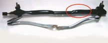
Commonality of Parts
In the cable-controlled system, it was possible for the cruise system
to malfunction without affecting normal throttle operation. In the new
system, because the same components operate the throttle blade for normal
and cruise driving, a failure will affect both at the same time (fig.
3). Put another way, there are no longer any unique cruise components
in the throttle controls to malfunction or to diagnose.
A Module
B Throttle Body
Disengage History Record
On your Tech 2, you can view the last 8 reasons why cruise control was
disengaged. This is a buffered list -- that is, the oldest item drops
off the list as a new one is added.
You may find this list useful when diagnosing customer concerns, such
as drop-out with the throttle depressed above the set speed, discussed
earlier.
TIP: The Disengage History records
all reasons, not just those that involve a DTC. In fact, the most common
reason you will probably see is Brake Applied.
The previous system also had this record, but it’s more comprehensive
in the new system. Depending on model, there are up to 38 items that
can be displayed.
Brake Application Before Engage
During each ignition cycle, the PCM must see one brake application before
the cruise control will engage. On automatic transmission vehicles,
this is satisfied by the brake application necessary to shift out of
PARK (BTSI). On manual transmission vehicles, a switch on the clutch
pedal serves the same function. The clutch must be depressed before
the starter can be engaged.
Clutch Application
On manual transmission vehicles, stepping on the clutch pedal causes
the cruise control to disengage, to prevent engine over-revving. The
RESUME button may be used to engage cruise control again.
-
Thanks to Ken Feliks and Kevin Fondaw |

figure
1 |
|

figure
2 |
|
|
| |
| |
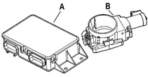
figure 3 |
|
|
|
|
| Know-How Broadcasts
for March |
| |
 |
| Know-How
Broadcasts for March |
| Emerging
Issues |
March
13, 2003 |
9:00
AM, 12:30 PM,
3:30 PM
Eastern Time |
| Technology
Close Up --
Tech 2 Functional Diagnostics and GM-LAN |
March
27, 2003 |
9:00
AM, 12:30 PM,
3:30 PM
Eastern Time |
| -
Thanks to Tracy Timmerman |
|
|
| |
|
|
Gas
Springs
|
GM
uses gas springs on rear liftgates in numerous vehicles. The springs perform
several functions:
- assist in raising the liftgate
- hold the liftgate in the raised position
- provide a controlled rate when the liftgate is closed (fig.
4).
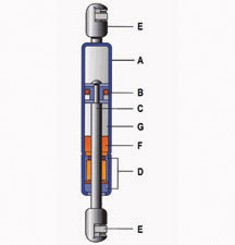
Operation
The gas spring looks somewhat like a shock absorber, although it doesn’t
work like one.
It consists of (A) pressure tube, (B) piston, (C) piston rod, (D) seal-guide,
and (E) appropriate connection fittings (fig. 5).
The gas spring is a hydropneumatic device, meaning it contains a liquid
(F - oil) and a gas (G - compressed nitrogen).
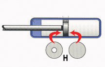
The compressed nitrogen acts with equal pressure on differently dimensioned
cross-sectional areas of the piston (fig. 6).
This produces a force in the extension direction (H). That is, the gas
spring, if left on its own, will extend fully.
The gas spring is designed to operate over a range of - 20°F (-30°C)
to 176°F (80°C). The compressed nitrogen in the gas spring behaves
just like any other gas in a confined space. Pressure moves up or down
along with temperature.
In normal temperatures (warm weather), the gas pressure
is higher. This means that the gas spring may offer sufficient force to
assist in raising the liftgate. It offers enough force to hold the liftgate
in the open position. And when the liftgate is closed, it provides enough
resistance to prevent the liftgate from slamming shut.
When the temperature drops (cold weather), so does the
gas spring’s internal pressure. Under these conditions, the liftgate
may not auto-rise due to the reduced assistance in opening, although it
will still hold the liftgate open. And it may offer reduced resistance
when the liftgate is closed.
TIP: All of these characteristics
are normal and a gas spring should not be replaced if the liftgate performs
as described. Replacing a normal spring (that is cold) with a new spring
(that is warm) will appear to correct the “problem,” but it
will return as soon as the replacement springs are allowed to become cold.
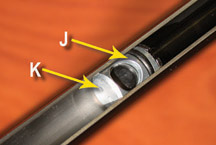
Hydro-Lift-T
The latest version of the gas spring is called the HLT, or hydro-lift
temperature controlled (fig. 7). The name
comes from a temperature sensitive bi-metal poppet valve in the piston
(J). It’s intended to minimize the effects of temperature on the
operation of the spring. At temperatures above 50°F (10°C) the
valve is inactive. Below this temperature, the valve closes and the holding
force increases. The gas must pass through a small orifice (K), against
the pressure of the bi-metal spring. This affects the flow of gas through
the piston when the gas spring rod and piston move into the pressure tube.
The effect is to provide extra holding force in the extended position
to ensure that the liftgate remains open. The HLT does not affect the
lift open effort or the closing resistance.
Replacement
Considering the operation of the gas spring when it is cold, you may wonder
how to tell if the spring should be replaced. Simple. If the springs do
not hold the liftgate up after it is opened.
On vehicles equipped with the new HLT gas spring system, the temperature
valve is contained in the LH spring, indicated by a red label. The RH
spring is indicated by a green label.
TIP: One exception is the Cadillac
Escalade, which uses a yellow label on the LH spring and a white label
on the RH spring.
TIP: When replacing gas springs,
be sure to check the parts book. There should be two numbers, one for
each side.
TIP: If you should install two red-labeled (or yellow-labeled)
gas springs, it will be very difficult to pull the liftgate shut. And
two green-labeled (or white-labeled) springs may not hold the liftgate
up when cold.
Gas springs should be installed with the piston rod pointing down when
the liftgate is open.
Maintenance
For a long service life, gas springs must not be subjected to bending
forces. If the spring or its mounting points are bent, the spring may
bind and not work properly.
Gas springs are designed for long life without maintenance. There is no
need to lubricate the piston rod. You should, however, be sure the rod
does not become contaminated (for instance with masking tape residue or
overspray from a paint repair).
A light film of oil will appear on the rod as the spring extends. This
is normal, and is for lubrication of the guide and seal.
Storage
If spare gas springs are stored in your parts department, be sure they
are placed with the piston rod pointing down. After a maximum storage
time of 6 months, the gas springs should be actuated.
Disposal
IMPORTANT: Wear appropriate eye protection.
When gas springs are no longer needed, they should be disposed of in an
environmentally correct manner. To accomplish this, drill the pressure
tube open, release the compressed nitrogen gas, and drain the oil.
- Thanks to Rich Staton, Stabilus |
 figure 4
 |
figure
5 |
figure
6 |
figure
7 |
| |
| |
| |
| |
| return
to Table of Contents |
| |
| 3
Step Maintenance Fuel Induction Service Kit Followup |
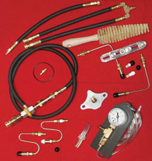
The
December 2002 issue of TechLink introduced a new GM Vehicle Care line
of products called the 3 Step Maintenance Fuel Induction Service Kit.
This followup is to clarify how to obtain the application tool kit and
the cleaner kits.
Tool Kit -- The tool kit includes sprayer tips, adapters,
hoses, gauge, and other items (fig. 8). To
obtain the tool kit, contact the vehicle care specialist at 1.800.955.8591
(1.800.323.4592 in Canada). The maintenance cleaner kits (solvents) can
also be purchased at this number.
TIP: Be sure to inquire about available
incentives when both are purchased together.
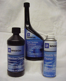
Maintenance Kit -- The kit consists of three different
cleaning solvents (fig. 9):
- Fuel System Treatment
- Throttle Body Cleaner
- Induction Cleaner
The GM part number is 12378546. In Canada the AC Delco part number is
88901337. The kits are sold by the case. Each case contains enough materials
to service 12 vehicles. Your parts department can use the computerized
RAPID ordering system or call the TRACS 2000 phone ordering system, 1.800.433.6961
(1.800.866.5832 in Canada).
-
Thanks to Rene Richardson
|
figure
8
|
figure
9 |
| return
to Table of Contents |
|
| Steering
Wheel Mode Button |
Owners
of 2003 Chevrolet Venture vans may be unable to locate information on
the steering wheel radio control 'mode' button in the owner’s
manual or in SI.
Steering wheel radio control information was completely omitted from
the initial owner manual printing. Individual SWRC button operation
is not found in SI. SWRC information may be found in other Chevrolet
Division owner’s manuals such as Monte Carlo or Impala.
For vehicles built with RPO UK3, this is a description of what the 'mode'
button is for. Press this button to choose AM, FM1 OR FM2. If a tape
or compact disc is playing, it will stop and the radio will play. It
will not allow switching back to other sources such as cassette or compact
disc.
-
Thanks to GM Technical Assistance |
| return
to Table of Contents |
|
| OnStar
Deactivation Strategy |
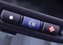
This
information affects 1999 through current model year vehicles equipped
with the three-button OnStar system (fig. 10).
OnStar has begun deactivating the OnStar system in vehicles when the
customer has chosen not to renew their OnStar subscription after expiration.
OnStar notifies customers that the OnStar system in their vehicle will
be deactivated unless they renew the account.
After successful deactivation, customers will experience the following
when attempting to contact OnStar from their vehicle:
Blue OnStar key -- the customer will be connected to a dedicated sales
team who can sell an OnStar subscription and reactivate the vehicle.
(On some vehicles, the customer may first hear a message stating there
is no current OnStar subscription for the vehicle, and directing the
customer how to activate services. A second press of the blue button
will connect to a dedicated sales group who can reactivate the vehicle.)
Emergency key -- a message will indicate the service has been deactivated.
On 1999 models, the operation of this key does not change with deactivation.
TIP: When successfully deactivated,
the OnStar system will not attempt to connect to the OnStar center if
the vehicle's front airbags deploy.
The system may not be able to establish a connection to the OnStar Call
Center in certain situations, such as when the VIU is replaced on a
deactivated system. When normal published diagnostic procedures do not
indiate a possible cause for the no-connect concern, the vehicle may
have been deactivated. Further diagnosis and repair is necessary only
if the customer elects to become an active OnStar subscriber.
TIP: On the Tech 2 under the program
phone option, you will notice that the phone number is 011.555.7529
or 123.456.7890 on all units that have been deactivated.
-
Thanks to Dale Tripp |
figure
10
|
| |
| return
to Table of Contents |
|
| Regular
Production Accessories (RPA) |
There are several terms used to describe options and accessories that
can be ordered with a new vehicle.
Regular Production Options (RPO) are installed on the vehicle at the assembly
plant.
IMPORTANT: Some factory equipment is “shipped
loose” with the vehicle for installation at the time of delivery.
These items may be standard equipment or RPOs. Examples include wheel
covers, radio antennas, and roof rack components.
Certain GM accessories can now be ordered at the same time the vehicle
is ordered. These are called Regular Production Accessories (RPA). The
accessory is listed on the vehicle’s window label and SPID label.
An example is the cargo net available with some Buick Rendezvous models
(RPA code AP9).
However, the RPA does not accompany the vehicle when it leaves the assembly
plant. Instead, the item is shipped directly to the dealership for installation
at the time of delivery. The package is identified with the vehicle’s
VIN when it arrives at the dealership.
IMPORTANT: These RPA parts must
not be installed on another vehicle. In fact, it’s
a good idea to store RPAs where they cannot be confused with normal parts
department stock.
RPAs generally fall into the category of items that an owner may otherwise
seek in the aftermarket. Examples may include cargo nets, floor mats,
luggage compartment mats, body kits, running boards, mud flaps, off-road
lights (fig. 11), and many more.
The advantage of ordering a factory RPA is that the item is designed specifically
for the vehicle. Mounting holes, component fit, and colors are perfect
matches for the vehicle, which may not be true of aftermarket items. And
RPAs are covered under the new vehicle warranty.
This ensures that the customer is able to obtain desirable accessories
conveniently, and because the items are considered factory equipment,
they can be included in the vehicle’s financing.
The labor time for installation of an RPA is handled as an add time to
the Pre-Delivery inspection time (labor operation Z7000). Other warranty
labor operations are not to be used for the initial installation of an
RPA.
- Thanks to Russ Gilbert |
| |
figure
11 |
|
return
to Table of Contents |
|
| Regular
Production Option Master List |
A
vehicle consists of standard equipment and in most cases some optional
equipment as well. For organizational purposes, optional equipment is
identified by a Regular Production Option (RPO) code.
Every vehicle contains a Service Parts Identification label (SPID) which
lists every RPO included on that vehicle.
Because there are so many RPOs in use, you will not be able to remember
them all. When you encounter an RPO code that is unfamiliar, there are
several ways to find out what it pertains to.
One way is to go to SI, “build” the vehicle, then look under
General Information. All of the RPOs available on the “built”
vehicle are listed, along with a brief description of each option.
Another way is to go to GM-VIS and input the VIN of a specific vehicle.
You will see a list of the exact RPOs included on that vehicle, again
with a brief description.
Now, there is another way. The current list of RPOs is found on the
TechLink website at http://service.gm.com.
Open the TechLink website and click on a language button. At the top
of the home page, locate the REFERENCE GUIDES tab. This will take you
to a directory of available reference materials.
Click on the RPO Master List. It includes every RPO code in use for
about 20 years, and they’re arranged in alpha-numeric order.
TIP: This list is huge, running
more than 18,000 items. You can scroll the list using your browser’s
scoll bar or up and down arrows.
- Thanks to Kevin Larson |
|
|
|
|
| return
to Table of Contents |
|
| New
Gasket Material |
According
to SPO bulletin IB03-008, a new material is being used for service replacement
transmission pan gaskets.
The previous black fiber material is superceded by UltraCork, comprised
of cork granules embedded in rubber. The advantages of UltraCork include:
- Resists breaking when folded
- Conforms to warped or uneven surfaces
- Improved sealability
- Better torque retention
- Smaller bolt holes, to facilitate installation by holding pan bolts
in place
- Improved thread sealing
The UltraCork transmission pan gasket will be included with the transmission
filter. The transition will occur as inventory of the current black
fiber gaskets is depleted.
- Thanks to GM Parts |
|
|
| return
to Table of Contents |
|
| Trailer
Controller Information |
The
following vehicles are affected:
2002-2003
- Cadillac Escalade, Escalade EXT
- Chevrolet Avalanche
1999-2003
- Chevrolet Silverado
- GMC Sierra
2000-03
- Chevrolet Suburban, Tahoe
- GMC Yukon, Yukon XL
2003
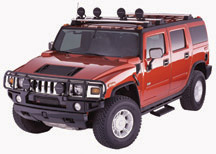
- Hummer H2
Some customers may comment that when the headlamps or park lamps are on,
the brakes on the trailer are always applied, or that the back lighting
for the trailer brake controller illuminates only when the brakes are
applied.
This condition may be due to wiring changes within the vehicle electrical
system for the 2003 model year.
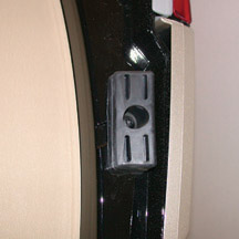
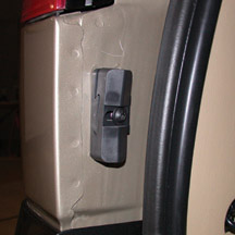
Inspect the brake controller wiring harness jumper that is plugged into
the vehicle relay block body. The relay block body is located under the
left side of the instrument panel near the left kick panel, behind a plastic
cover.
The 1999 through early 2003 wiring harness jumper that plugs into the
relay block will have a reddish/brown 6-way connector and a tag with the
last four digits of the wiring harness part number. Second design 2003
may have a white plastic connector with part number 5418 as well.
- The 1999 jumper is/was PN 12171982 with a pink/purple tag identifier
of 1982. This number has been superseded to 15366255, with a pink/purple
tag identifier of 6255.
- The 2000 jumper harness is PN 15366255. The pink/purple tag identifier
is 6255.
- the 2001-02 jumper is PN 15086884. The orange tag identifier is 6884.
- The 2003 jumper is PN 15085418. The orange tag identifier is 5418.
When transferring the brake controller with the wiring jumper attached
from a 2001-02 vehicle to a 2003 vehicle, a change to the jumper harness
connector must be performed.
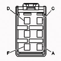
The following information is for the 1999-2002 wiring harnesses.
1999-2002
Wiring Harnesses |
| PIN |
WIRE
COLOR |
CIRCUIT
NUMBER |
FUNCTION |
| A |
Lt blue |
1620 |
Stop Lamps |
| B |
Red |
142 |
Brake Controller
12 Volt Source |
| C |
Dk blue |
47 |
Brake Controller
Outpu
(Trailer Brakes) |
| D |
Brown |
2409 |
Brake Controller
Illumination |
| E |
-- |
--
|
-- |
| F |
Black |
1850 |
Ground |
The following information
is for the 2003 wiring harness.
2003
Wiring Harness |
| PIN |
WIRE
COLOR |
CIRCUIT
NUMBER |
FUNCTION |
| A |
Brown |
2409 |
Brake Controller
Illumination |
| B |
Red |
242 |
Brake Controller
12 Volt Source |
| C |
Dk blue |
47 |
Brake Controller
Outpu
(Trailer Brakes) |
| D |
Lt blue |
1620 |
Stop Lamps |
E |
-- |
--
|
-- |
F |
Black |
1850 |
Ground |
To modify a 12171982,
15366255 or 15086884 harness for use in a 2003 vehicle, switch the wires
in cavities A and D.
To modify a 15085418 harness for use in a 1999-2002 vehicle, switch the
wires in cavities A and D (fig. 12).
-
Thanks to Jim Maddy
|
| |
figure
12
return
to Table of Contents |
|
| Liftgate
Wedge Change |
As
a running change to 2003 Ventura, Montana, Silhouette minivans and Aztek,
a different liftgate wedge is being installed. This is the same wedge
used on the Buick Rendezvous.
The liftgate trim panel is being revised to accommodate the shape of
the new wedges. There should be a 6 mm gap between the panel and the
wedges, right and left.
The wedge consists of two parts, the liftgate side and the body side.
Wedge -- Liftgate Side
The liftgate side wedge is attached by a single screw. It is tightened
to 89 lb in (10 N.m). (fig. 13)
Wedge -- Body Side
The body side wedge consists of a spacer and a wedge, and is attached
by a single screw. Before loosening the screw, mark the location of
the wedge on the spacer. Remove the screw and slide the wedge rearward
off the spacer. Pry the spacer off with a flat-blade tool.
(fig. 14)
Install the spacer to the body. Slide the wedge onto the spacer to the
previously marked location. Tighten the screw to 89 lb in (10 N.m).
TIP: There are three different
spacers, one for Rendezvous, one for Aztek, and one for the minivans.
-
Thanks to Mike Muglia |
figure
13 |
figure
14 |
| return
to Table of Contents |
|
| Revised
Windshield Wiper System |
A
revised windshield wiper system will be installed as a running change
on 2003 Chevrolet Cavalier and Pontiac Sunfire beginning in January
(VIN 7 on January 2, VIN S on January 11). The 2003 Pontiac Grand Am,
Chevrolet Malibu and Oldsmobile Alero will be added on February 3.
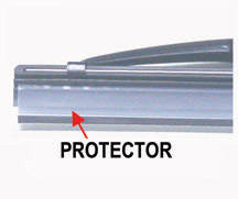
Taking the most obvious first, a protective plastic sleeve is installed
on the wiper blade at the factory (fig. 15).
Gaps in the hook clip and lever of the blade assembly have been reduced
to reduce noise and chatter, and to improve winter performance.
The controller assembly now operates digitally instead of with variable
voltage, providing a more reliable interval wipe.
The manufacturing process for the frame tube and transmission housing
has been simplified, and it is more stable.
And finally, the new assembly weighs about 11 ounces (300 grams) less
(fig. 16).
Service Considerations
TIP: Leave the blade protectors
in place until just before the vehicle is delivered, to prolong blade
life.
TIP: Parts are not interchangeable
between the earlier system and the new one. Consult your parts catalog
for the appropriate numbers.
-
Thanks to Steve Oakley |
figure
15 |
figure
16 |
| return
to Table of Contents |
|
| Synthetic
Front Axle Lubricant |
IMPORTANT:
This information is intended for vehicles sold in very cold weather climates,
especially those in Alaska and certain regions of Canada.
An upcoming bulletin addresses the use of synthetic front axle lubricant
for 4wd C/K trucks with 9.25-inch front axle assemblies sold in cold weather
climates.
TIP: Provide a copy of the bulletin
to the owner when the lubricant is replaced.
The mineral based fluid used in the front axles of these vehicles may
not lubricate properly at -12°F (-24°C) or below. This may contribute
to premature pinion bearing wear if a vehicle is driven extensively in
very low ambient temperatures.
Before delivery to the first retail customer, the front axle fluid should
be drained and refilled with synthetic axle lubricant, following the service
manual procedure (document 673354).
It is not necessary to flush the front axle assembly. Use Synthetic Axle
Lubricant 12378261 (Canadian 10953455). The approximate fluid capacity
is 1.83 qts. (1.73L).
After changing the lubricant, inspect the front axle vent hose connector
(fig. 17). The black type is not compatible
with synthetic lubricants. If necessary, install vent connector 12479296,
following the service manual procedure (document 843184).
TIP: If the vent hose connector
assembly is white, it does not need to be changed.
-
Thanks to Rich Burrell and Ed Laskowski
|
figure
17 |
| return
to Table of Contents |
|
| Air
Vent Flutter |
Owners
of some 2002-03 Chevrolet Venture, Oldsmobile Silhouette and Pontiac Montana
vehicles may comment on a fluttering sound from an I/P air vent when the
fan is set on medium or high.
This may be caused by a dislodged strip of foam gasket on one of the air
shutters.
Repair requires removing the air discharge outlet by pushing in at the
top left corner and pulling out at the lower right. After the outlet pops
out, remove the airflow adjusting wheel.
Pull out the shutter and observe where the gasket is dislodged (fig.
18).
Pull the gasket partially out of the retaining groove and apply hot glue
three places: at the center, and right and left of center. Reseat the
gasket and allow the glue to set.
Repeat with the other edge of the gasket.
Install the shutter, wheel and outlet.
Refer to bulletin 02-01-37-008 for details.
-
Thanks to Tom Geist
|
figure
18 |
| return
to Table of Contents |
|
| Power
Seat Adjuster Inoperative |
Owners
of some 2001-2003 Buick Century and Regal and Chevrolet Impala and Monte
Carlo may comment that the horizontal or vertical power seat adjuster
in the driver or passenger seat is inoperative.
The power seat adjuster cables may have been damaged or disconnected
by objects pushed under the front seat.
Reconnect or replace the power seat adjuster horizontal or vertical
cables. Refer to the Drive Cable Replacement -- Horizontal and Vertical
procedures in the Seats sub-section of the Service Manual (SI Documents
964600 and 964621).
Up to now, it was necessary to replace the entire seat adjuster assembly
because the individual cables were not available separately.
Parts are currently available from GMSPO.
-
Thanks to Mel Spresney and Maurine Miller
|
| |
| return
to Table of Contents |
|
| Bulletins
– January, 2003
This review
of service bulletins released through mid-January lists the bulletin
number, superseded bulletin number (if applicable), subject and models. |
00
– General Information
02-00-89-018; LD Truck Dealers Servicing Chevrolet Kodiak and GMC TopKick
(C4500) Vehicles; 2003 Chevrolet Kodiak and GMC TopKick C4500 Series
01 – HVAC
02-01-37-008; Fluttering Sound From I/P Air Vent (Glue Air-Shutter Sealing
Foam); 2002-03 Chevrolet Venture, Oldsmobile Silhouette, Pontiac Montana
02-01-38-004; Air Conditioning is not Cold Enough (Replace Condenser);
2002 Buick Rendezvous, 2001-02 Chevrolet Venture, Oldsmobile Silhouette,
Pontiac Aztek, Montana
02-01-38-005; Revised Heater/Vent Module Replacement; 1998-2002 Chevrolet
Blazer, S-10, GMC Jimmy, Sonoma, Oldsmobile Bravada
02-01-38-006; Revised Compressor Oil Balancing Procedure; 2002 Chevrolet
TrailBlazer, GMC Envoy, Oldsmobile Bravada
02-01-38-007; Poor A/C Performance -- A/C Will Not Blow Cold Enough
(Perform A/C System Checks); 2003 Chevrolet Silverado, GMC Sierra with
6.6L Diesel Engine (VIN 1 -- RPO LB7)
02-01-39-008; A/C Compressor Inoperative, A/C Cycles too Often, Insufficient
Cooling, DTC P0530 (Replace A/C High Pressure Valve); 2002-03 Buick
Rendezvous, Chevrolet Venture, Oldsmobile Silhouette, Pontiac Aztek,
Montana with Mitsubishi Air Compressor
03 – Suspension
02-03-08-008; Rattle/Creak/Popping Type Noise from Front of Vehicle
When Turning (Replace Both Front Stabilizer Shaft Insulator Brackets);
2002-03 Chevrolet Cavalier, Oldsmobile Alero, Pontiac Grand Am, Sunfire
with FE1 or FE2 Suspension
04 – Driveline Axle
02-04-17-003; Boom Noise or Vibration (Rotate/Reinstall Front Propeller
Shaft to Axle); 2003 Chevrolet Express, GMC Savana 1500/2500 AWD Vans
05 – Brakes
02-05-25-006A; replaces 02-05-25-006; Antilock Brake (ABS) Activation
at Low Speeds (Clean Wheel Speed Sensor Mounting Surface); specified
truck vehicles between 1995-2003
06 – Engine/Propulsion System
00-06-01-023B; replaces 00-06-01-023A; Engine/Balance Shaft “Rattle”
Noise; 1992-2003 Chevrolet and GMC C/K, S/T, M/L, G and P Models, Oldsmobile
Bravada with 4.3L V6 Engine (VINs W, X -- RPOs L35, LF6, LU3)
01-06-01-002A; replaces 01-06-01-002; Revised Piston Pin Removal/Installation
Procedures; specified 1994-99 Vehicles with 3.1L Engine (VIN M -- RPO
L82)
02-06-01-038; Engine Knock or Lifter Noise (Replace O-Ring); 2001-03
Cars and LD Trucks with 4.8L, 5.3L, 5.7L or 6.0L V8 Engine (VINs V,
T, Z, G, S, N, U -- RPOs LR4, LM7, L59, LS1, LS6, LQ9, LQ4)
02-06-02-011A; replaces 02-06-02-011; Engine Overheating and/or Excessive
Noise from Electric Cooling Fan Motor (Install Cooling Fan Shield and
Cooling Fan Module Motor Shroud Assembly, If Necessary); 2000-02 Chevrolet
Impala with specified RPOs
02-06-03-006A; replaces 02-06-03-006; No Start, No Crank, Battery, Batteries,
Generator, Gages, SES, SIR, Brake, Security, Theft, ABS, Hot, DIC Messages,
Lamp, Light, Battery and Generator Diagnostic Testing, and Cadillac
Roadside Service, Warranty Claims Procedure (Proper Diagnostic Procedures);
1997-2003 Passenger Cars and Trucks (except electric vehicle), Hummer
H2
02-06-03-011; Electrical System Diagnostic Work Sheet; 1997-2003 Passenger
Cars and LD Trucks, 2003 Hummer H2
02-06-04-054; Increased Accelerator Pedal Effort (Clean Throttle Body
and Adjust Blade); specified vehicles with 4.8L or 5.3L V8 Engine (VINs
V, T, Z -- RPOs LR4, LM7, L59)
02-06-04-056; Gasoline Auxiliary Generator Will Not Run When Vehicle
is Off (Replace Fuel Sending Unit With Non-RFCV Fuel Sending Unit);
2002 Chevrolet Express, GMC Savana Van with RPOs K50 (Fuel Fitting,
Line Take Off) and/or 7T6 (Fuel Fitting, Line Take Off)
02-06-04-057; Labor Operation Assignments for Vehicle Control Module
Reprogramming; 2003 and Prior Passenger Cars and Trucks, Hummer H2
02-06-04-058; SES Lamp Illuminated, False DTCs P0181 and/or P0116 (Reprogram
ECM); 2001-02 Chevrolet Silverado, GMC Sierra 2500/3500 with 6.6L Duramax
Diesel Engine
02-06-04-060; Automatic Engine Shutdown Feature; 1997-2001 Chevrolet
and GMC F Model MD Tilt Cab with Air Brakes (RPO JE4) and Automatic
Engine Shutdown (RPO KPJ)
07 – Transmission/Transaxle
99-07-30-030B; replaces 99-07-30-030A; Grinding and/or Growling Noise
in Park on Incline; 2003 and Prior FWD Passenger Cars with Hydra-Matic
Front Wheel Drive Automatic Transmission
01-07-30-036B; replaces 01-07-30-036A; Diagnostic Tips for DTC P0756;
2001-03 Passenger Cars and LD Trucks with 4L60E or 4L65E Auto Transmission
(RPO M30 or M32)
02-07-30-039A; replaces 02-07-30-039; Firm Transmission Shifts, Shudder/Chuggle,
Transmission Won’t Downshift On Deceleration, SES Light Illuminated,
DTC P0742 Set (Perform Diagnostics and Replace TCC PWM Solenoid); 2003
Vehicles with 4T65E Transaxle (RPO MN3, MN7, M15, M76) or 4T40E/4T45E
Transaxle (RPO MN4 or MN5)
01-07-30-042A; replaces 01-07-30-042; Information on 2-3 Upshift or
3-2 Downshift Clunk Noise; 2003 and Prior LD Trucks with 4L60E or 4L65E
Auto Transmission (RPOs M30, M32)
02-07-30-046; Newly Designed Transaxle Valve Body and Oil Pump Service
Information; specified 2002-03 vehicles with 4T65E Transaxles, RPOs
MN3, MN7, M15, M76
02-07-30-050; Engineering Changes to Valve Body, Pressure Regulator
Valve, 2-3 Accumulator Valve and Bore; applicable 1995-2003 Chevrolet
Cavalier, Malibu, Oldsmobile Cutlass, Alero, Pontiac Sunfire, Grand
Am with 4T40E or 4T45E Transaxle (RPOs MN4 or MN5)
02-07-30-051; Transmission Shifting In and Out of 4th and 5th Gear (Hunting)
When Pulling/Carrying a Load, Unable to Manually Select 4th Gear (Install
5th Gear Inhibit Switch); 2001-02 Chevrolet Silverado, GMC Sierra with
6.6L Diesel or 8.1L Gas Engine (VINs 1, G -- RPOs LB7, L18) and Allison
Auto Trans (RPO M74)
02-07-30-052A; replaces 02-07-30-052; Essential Tool J-45096 TransFlow;
2003 and Prior Passenger Cars and LD Trucks with Automatic Transmission
(except M74 Allison)
08 – Body and Accessories
02-08-42-006; Relay Omitted for Bodybuilder Connection/Upfitter Provision;
2003 Chevrolet and GMC W3500/4500 MD Tilt Cab Models
02-08-44-016A; replaces 02-08-44-016; Whine, Buzz, Generator Whine,
Whine Type Noise Heard on Acceleration (Repair Vehicle Sound System
Wiring); 2002 Chevrolet TrailBlazer, GMC Envoy, Oldsmobile Bravada
02-08-44-019; Revised Audio System Diagnostic; 1998-2000 Pontiac Firebird,
Chevrolet Camaro
02-08-44-020; No Audio Out of Speakers at Times (No Permanent Repair
Available at this Time); 2003 Cadillac Escalade, Chevrolet Avalanche,
Silverado, Suburban, Tahoe, GMC Sierra, Yukon, Hummer H2
02-08-44-022; Static Noise Heard in Radio Speakers (Install Capacitor
into Rear Differential Clutch Check Valve Circuit); 2002-03 Buick Rendezvous,
Chevrolet Venture, Oldsmobile Silhouette, Pontiac Aztek, Montana with
All Wheel Drive
02-08-50-010; Power Seat Adjuster Inoperative (Reconnect or Replace
Adjuster Cables); 2001-03 Buick Century, Regal, Chevrolet Impala, Monte
Carlo
02-08-62-004; Front Fascia Wavy (Install Dual Lock); 2002-03 Chevrolet
TrailBlazer, EXT
02-08-64-024; Discoloration/Fading of Door Glass Molding; 2002 Chevrolet
TrailBlazer, GMC Envoy, Oldsmobile Bravada
02-08-64-026; Power Sliding Side Door Hard to Open (Replace Lock Rod);
2002-03 Chevrolet Venture, Oldsmobile Silhouette, Pontiac Montana (Long
Wheel Base Only, with Manual or Power Sliding Side Door)
02-08-67-006A; replaces 02-08-67-006; Roof Perforation (Replace Roof);
1997-2003 Chevrolet Venture, Pontiac TransSport/Montana, Oldsmobile
Silhouette
|
| return
to Table of Contents |
|
|
| |
|
|
|
| |
|
|
|
| |
|
|
|
|
