| |
| |
Note: Click a picture or illustration in the left column to view a large version in the article.
To hide the large version, simply click on it.
|
|
Vac-N-Fill (GE-47716) |
The GE-47716 Coolant Refill System (also referred to as the Vac-n-Fill) is an essential tool, shipped to dealers in November 2004 (fig. 1). This tool is used when refilling a cooling system that has been drained.
In many cases, simply pouring fresh coolant into the cooling system allows a certain amount of trapped air to remain in the cooling system. Typically, thermal-cycling the engine (warm-up and cool-down) helps purge this air. But on some engines, there are remote pockets where air may be trapped. Using the Vac-n-Fill removes all air from the cooling system.
A venturi assembly in the tool uses high-pressure shop air to create a vacuum in the vacuum tank on the top of the tool. The vacuum is then applied to the cooling system. Once the vacuum is maximized (indicated by the built-in gauge), a release valve allows the vacuum to draw fresh coolant from the tool’s reservoir into the system. One or two repetitions of this process will usually fill the cooling system and will purge all air.
TIP: For more information on operating the GE-47716 Coolant Refill System, see the GM Tool Organization DVD/Software (J-43921-G v8.0).
Vacuum Tank Cleaning Procedure
IMPORTANT: Do not disassemble the vacuum tank. Doing so will void the warranty. Resealing the vacuum tank in the field is very difficult and should not be attempted.
If the vacuum tank (fig. 2) on the GE-47716 becomes excessively dirty and cleaning needs to be conducted, follow this procedure:
1. Remove all hoses from the tank.
2. Open the drain valve and drain any fluid from inside the tank.
3. With drain valve still open, pour in a solution of water and mild soap.
4. Close the drain valve and agitate the tank.
5. Open the valve and drain the solution.
6. Repeat procedure with clean water to remove any remaining soap residue.
- Thanks to Russ Dobson and Kevin Willcock |
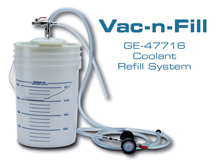
figure 1 |
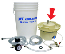
figure 2
return
to Table of Contents
|
|
CANdi & Tech 2 – A Necessary Combination for GM LAN Diagnostics
return
to Table of Contents
|
Did you know that at least one controller on every 2006 General Motors vehicle uses Controller Area Network (CAN) communication protocols? This is the method used by controllers on GM vehicles to talk to one another. It’s also called GM LAN.
Your Tech 2 requires an interface called the CANdi Module to communicate properly with GM LAN controllers. CANdi stands for Controller Area Network Diagnostic Interface. As more vehicles use GM LAN, it becomes increasingly important to equip each Tech 2 with a CANdi Module to take full advantage of the service data on the vehicle.
According to a recent analysis, the typical GM dealership has only one CANdi module for every three Tech 2s they own. This is not an effective ratio of CANdi Modules to Tech 2s for efficient fix-it-right-the-first-time customer service. Each Tech 2 should be equipped with its own CANdi Module. With some programming events taking as long as an hour to complete, the time waiting for a CANdi Module is lost money.
Check out the first-quarter specials from GM Tools. There are specials on Tech 2 packages and a 15% discount on all accessories, including the CANdi Module. Contact SPX/Kent-Moore at 1.800.GMTOOLS for details.
TIP: Dealers outside of the US should call for pricing and details.
- Thanks to Dan Doss |
|
| GM Vehicle Care Odor Eliminator Application Instructions |
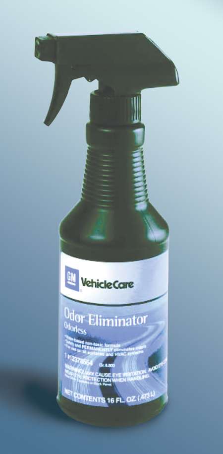
GM offers an odorless, water based, non-toxic odor eliminator (TechLink, March 2002) (fig. 3). It safely and permanently eliminates odors from all surfaces and HVAC systems. The 16 oz. container is available under GM part number 12378554 (88901678 in Canada).
Instructions are included with the product. For carpet and upholstery, after checking for color fastness, you can spray the product directly onto the odor source, brush into the fabric to ensure penetration, and blot excess moisture. For ventilation systems, spray directly into the cowl intake. At a cool setting, run the fan on high for several minutes. Then set the AC on max and run the fan for several more minutes. You can also add the product to the soap reservoir on shampoo equipment.
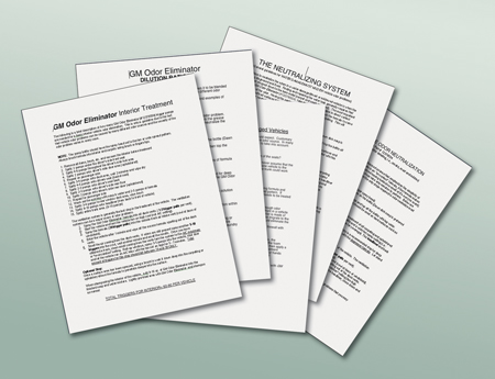
TIP: If you misplace the instruction sheets that come with the product, please do not call the manufacturer. All five pages of instructions for use (fig. 4) are now available in the Reference Guide on the TechLink website:
- Interior treatment
- Dilution ratios
- Water damage, musty, mildew odor
- Trouble shooting for water damaged vehicles
- Used vehicle odor neutralization
- Thanks to Alan Srodawa |

figure 3

figure 4
|
|
return to
Table of Contents |
|
Electrical Terminal Tool Kits |
SPX/Kent-Moore is is now offering two tool packages to provide technicians with the latest terminal testing and repair tools, at a reduced price.
The .64 terminals have become commonplace within GM wiring harnesses, and their small size makes them susceptible to damage if the incorrect release tool or test probes are used.
These tool packages were developed to address concerns that the tools may not be readily available in dealerships due to the tools’ small size and high demand.
J-35616-1
The first package is a .64 Service Kit and it consists of:
- one J-38125-21 (15381651-1) Delphi .64 Terminal Release Tool
- a pair of J-35616-64B Male .64 Test Probes.
The release tool is required to remove the Delphi .64 terminal from the connector body.
The male .64 test probes are used to properly test female .64 terminals without damaging the terminal.
J-35616-250
The second package is a Male Test Probe Refill Kit. It consists of one pair each of these Male Test Probes:
- J-35616-2A
- J-35616-4A
- J-35616-6
- J-35616-35
- J-35616-64B
These test probes are used to properly test the five most popular female terminals used in GM vehicles, without damage to the terminals being tested.
Special Prices
Tool |
Sale Price * |
Regular Price * |
J-35616-1
.64 Service Kit |
$30.81 |
$44.01 |
J-35616-250
Male Test Probe
Refill Kit |
$57.30 |
$81.86 |
* Prices quoted are US dollars; dealers outside of the US should call for pricing.
The special prices will be available February 1 through August 1, 2006. Promotional materials will be sent electronically to all dealers and posted in the VSSM library. For additional information, please contact SPX/Kent-Moore at 1.800.GM TOOLS (800.468.6657) or visit WWW.GMDE.net.
- Thanks to Greg McDonald |
return
to Table of Contents |
|
| Integral Connector Position Assurance (CPA) |
An article in the August 2005 issue of TechLink discussed the introduction of connection systems with an integral connector position assurance (CPA) (fig. 5). If not operated properly, the CPA can be damaged during removal of the connector, which can cause DTCs to be set after the CPA is pressed into place.
If the CPA is fully removed from the connector housing or damaged in any way, it must be replaced. This CPA (p/n 54590003) is available in the SIR tray of the terminal repair kit.
The photos in the article portrayed the FCI connection system called ABX4, which was introduced on the 2005 midsize pickup trucks.
The system is also being used on these additional vehicles:
- 2006 Impala and Monte Carlo
- 2006 Chevrolet Corvette
- 2006 Buick Lucerne
- 2006 Cadillac DTS
- 2006 mid-size utilities
- 2007 Buick LaCrosse/Allure
- 2007 full-size utilities
Refer to the August 2005 issue for detailed instructions. You may find back issues on the TechLink website, accessible through DealerWorld.
- Thanks to Kirk Reinbold |
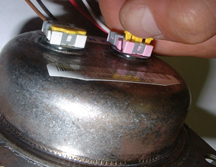
figure 5
return
to Table of Contents
|
|
Remote Vehicle Start Kit Followup |
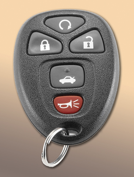
As explained in the June 2005 TechLink, a remote vehicle start (RVS) kit (fig. 6) is available for dealer installation in the following 2006 vehicles:
- Chevrolet Malibu
- Pontiac G6
- Buick Terraza
- Chevrolet Uplander
- Chevrolet Uplander
- Saturn Relay
- Pontiac Grand Prix
- Buick LaCrosse/Allure
- Chevrolet Impala
- Chevrolet Monte Carlo
- Buick Lucerne
TIP: A kit will also be available for the upcoming 2007 full-size Chevrolet and GMC utilities.
IMPORTANT: To qualify for installation of the RVS accessory kit, the vehicle must be equipped with an automatic transmission and RPO AP8. While AP8 may be standard equipment on some vehicles, it must be ordered for others.
For answers to questions you may have about model application, VIN code, and the part numbers for the applicable installation kit and instruction sheet, go to the TechLink website. Click on the Reference Guide tab, then scroll down to Remote Start Kit Applications. Click to open the application table.
- Thanks to Sharon Folts |

figure 6
|
|
return to Table of
Contents |
|
| 2005-06 Secondary Air Injection (SAI) Systems |
SAI System Operation
The Secondary Air Injection (SAI) is an emission control sub-system that normally operates upon initial cold or warm engine start-ups. The AIR pump supplies pressurized fresh air into the exhaust system to accelerate catalyst operation. This reduces HC and CO emission levels.
Early SAI systems used a large continually running mechanical pump driven by an accessory belt (a power robbing device) with noisy, vacuum-powered control switching.
The latest SAI system uses a small maintenance-free electric motor that runs for approximately 20 – 30 seconds with a whispering hum.
The AIR pump (fig. 7) is calibrated to operate when the engine start-up coolant temperature is between 41° F (5° C) and 122° F (50° C) and the ambient air temperature is between 41° F (5° C) and 140° F (60° C).
TIP: To avoid damage from frozen moisture in the system, the AIR pump will not run when the ambient air temperature is below 41° F (5° C).
When the engine is at operating temperature and the catalyst is warm enough to operate efficiently, the AIR pump is not required.
Features of the New Pressure Based SAI system
Components of the SAI system are familiar, with the exception of the new pressure sensor. The operation of the pressure sensor is similar to that of a Fuel Tank Pressure (FTP) sensor.
Earlier SAI systems used the HO2S sensor for diagnosis and verification of SAI system operation.
The new generation of SAI has a pressure sensor built into the electronic shut-off valve, which creates a more precise way to determine what is happening in the system. The Engine Control Module (ECM) detects abnormal conditions like a pump that is running continuously, or a shut-off valve that is stuck open.
Here are some additional changes to the AIR pressure based diagnostic system.
The pump inlet hose is routed to the air cleaner housing. This location allows the engine air filter to supply clean air and eliminates water intrusion into the AIR pump.
The in-rush current of the AIR pump is approximately 120 amps. During continuous operation, the current draw is 20 to 25 amps. In a high current circuit like this, resistance as low as 2 to 3 ohms anywhere in the pump circuitry may adversely affect pump operation.
The New Electronic Shut-Off Valve
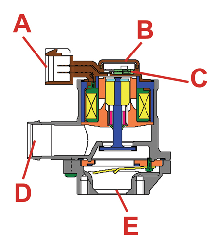
The electronic control shut-off valve (fig. 8 and 9) (also known as the AIR control solenoid valve/pressure sensor assembly or check valve assembly) contains:
- A pressure sensor, for monitoring airflow pressure
- A control valve that allows pressurized air from the pump to flow to the exhaust manifold
- An electrical solenoid that operates the control valve
- A check valve that keeps exhaust gases from damaging the assembly and the rest of the system
The valve has no removable parts. The solenoid, check valve, and pressure sensor are serviced as an assembly (fig. 10).
A New 5-pin connector
B Electronic solenoid
C Pressure sensor
D Inlet
E Outlet to exhaust manifold
The highly robust shut-off valve opens reliably when commanded ON by the ECM. Conditions such as low manifold vacuum, high altitude, or heavy acceleration have no adverse effects on the operation of the valve. The ECM supplies the AIR pressure sensor with the following circuits:
- 5-volt reference
- Low reference ground
- A signal circuit that provides the control module with a voltage relative to internal AIR pressure changes.
The AIR solenoid has the following circuits:
- A voltage circuit supplied by the AIR solenoid relay
- A ground circuit
The ECM also supplies the AIR pump and AIR valve relays with separate control (ground) circuits.
The ECM compares measured AIR pressure values with predicted values to detect faults with:
- The AIR pump
- The AIR control solenoid valve/pressure sensor assembly
- The system hoses and pipes
- The AIR pressure sensor and relay control circuits.
Diagnosis
There are 3 phases of the SAI diagnostic:
- Phase 1 -- The ECM commands both the AIR pump and AIR check valve relays ON.
- Phase 2 -- The ECM continues to command the AIR pump relay ON and also commands the AIR valve relay OFF.
- Phase 3 -- The ECM commands both the AIR pump and AIR check valve relays OFF.
The increased number of DTCs now associated with SAI will help easily diagnose and repair the fault in the system. The following DTCs set when an AIR system fault is detected:
TIP: The P2444 diagnostic code is a type A. All of the others are type B, which illuminate the MIL on the second drive trip.
- DTC P0411 -- During Phase 1, an AIR system insufficient airflow condition has been detected due to a malfunctioning:
- AIR Check Valve
- AIR pump
-AIR relay and related control circuit
- AIR pipe or hose restriction or leak.
- DTC P0412 -- An AIR valve relay coil circuit fault has been detected. This diagnostic runs continuously.
- DTC P0418 -- An AIR pump relay coil circuit fault has been detected. This diagnostic runs continuously.
- DTC P2430 -- An AIR pressure sensor signal change fault has been detected during Phase 1 and /or Phase 2.
- DTC P2431 -- An AIR pressure sensor value versus the BARO sensor value fault has been detected. This diagnostic runs continuously.
- DTC P2432 -- The AIR pressure sensor signal voltage is below the minimum range of the sensor. This diagnostic runs continuously.
- DTC P2433 -- The AIR pressure sensor signal voltage is above the maximum range of the sensor. This diagnostic runs continuously.
- DTC P2440--An AIR system airflow leak has been detected during Phase 2.
- DTC P2444 -- An AIR pump stuck ON fault condition has been detected during
Phase 3.
SAI System Verification
The following procedure determines if the SAI system is operating as designed:
1. Start and idle the engine for about 2 minutes to allow the SAI diagnostic to run and complete.
2. The start-up coolant and ambient air temperatures have to be in the specified operating range.
3. Monitor the AIR pressure parameter with a Tech 2.
4. Command the AIR pump relay ON. Only the AIR pump should operate.
The Tech 2 parameter will indicate only that the AIR pump relay is commanded ON.
5. Command the AIR solenoid valve relay ON. The AIR pump should operate and the AIR solenoid/check valve should open. The Tech 2 parameter will indicate that both AIR relays are commanded ON.
6. The AIR pressure parameter should increase. The difference in readings between step 3 and step 6 should be greater than 10kPa.
If it’s less than 10kPa, review the scan tool DTC information and refer to SI for service procedures.
TIP: The SAI system diagnostic tests may call for bypassing the AIR pump relay with a 60A fused jumper wire. The AIR shut-off valve will remain closed, causing a deadheaded condition. This builds an abnormal amount of heat in the pump. DO NOT operate the AIR pump for more than 30 seconds under these conditions.
TIP: When using the Tech 2 to command the AIR pump ON, a timer in the ECM and Tech 2 will automatically stop AIR pump operation. This will avoid overheating and damaging the AIR pump motor.
TIP: AIR pump operation is affected by system voltage. If the electrical system is not operating properly, correct the condition before diagnosing the SAI system.
- Thanks to Frank Tornambe and Michael Schallmo |
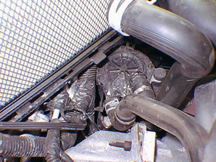
figure 7 |
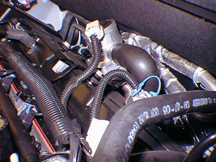
figure 8 |
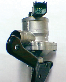
figure 9 |

figure 10
|
| return
to Table of Contents |
|
|
SIR System Disabling and Enabling Procedure -- New
return
to Table of Contents |
A bulletin is being released explaining the new SIR system disabling and enabling procedure for all 2003-06 GM cars and trucks.
IMPORTANT: Refer to the bulletin for details and follow the procedure exactly. Here are some highlights only.
Past experience, ongoing testing, and improved quality and reliability of the Supplemental Inflatable Restraint (SIR) systems enables simplification of the SIR Disabling and Enabling procedure. Testing has shown that it is not always necessary to disconnect air bag(s) in the area of repairs.
The new SIR Enabling and Disabling procedure is less invasive (therefore eliminating potential squeak and rattle conditions that may occur from the previous procedure) and is a simpler and quicker approach.
Future designs will eliminate certain deployment loop in-line connectors. Removing the in-line connectors makes the SIR deployment loop even more robust.
The new SIR Enabling and Disabling procedure requires only a fuse removal and/or the negative battery cable disconnect.
Deployment power is available for as much as one minute after disconnecting the vehicle power. Waiting one minute before working on the system after disabling the SIR system prevents deployment of the air bags from the reserved energy supply.
IMPORTANT: Refer to the bulletin for details and follow the procedure exactly.
- Thanks to Chuck Weiseckel
|
|
SES Light On (AFM Engine)
return to Table of
Contents
|
Bulletin 06-06-04-001 is being released to cover 2005-06 Chevrolet Impala, Monte Carlo, TrailBlazer, GMC Envoy and Pontiac Grand Prix with 5.3L Active Fuel Management (AFM) Engine (RPO LH6 or LS4).
The customer may comment that the SES light is on, but no other driveability or performance concerns are reported.
The most likely cause is that the fuel injector connectors are crossed or incorrectly installed. For example, the number 6 fuel injector connector may be plugged into the number 8 fuel injector and vice versa.
Refer to the bulletin for details. Here are some highlights.
Begin by using a scan tool to check for DTC(s) and write them down.
IMPORTANT: Do not assume that the fuel injector connectors are properly installed on the correct fuel injectors from the factory.
Use the appropriate SI fuel injector schematic to verify that the fuel injector connectors are installed on the correct fuel injectors. If necessary, install the fuel injector connectors correctly.
TIP: If you find that the fuel injector connectors are correctly installed, refer to the appropriate SI document for diagnosis of the DTC(s) noted at the beginning.
Finally, road test the vehicle at steady highway speeds, allowing the vehicle to go into AFM to verify the repair.
- Thanks to Tom Smith |
|
|
Trailer Wiring Harness ID |
When installing a trailer brake module or trailer connector on a 2003-06 Chevrolet Express or GMC Savana with RPO Z82 and/or UY7, it is necessary to know the location of the harness and what each wire is used for.
The four-wire trailer brake controller harness is located on the driver's side, under the instrument panel, taped to the pass-through main harness, between the park brake pedal and the vehicle brake pedal.
The seven-wire harness assembly is taped together and located in a frame pocket at the driver side rear left corner of the frame.
TIP: Both harnesses come without connectors.
The following tables include the color of each blunt-cut wire and its purpose.
- Thanks to Ron Erman
Four-Wire Harness
(Trailer Brake Controller) |
Black |
Ground |
Red/White Stripe |
Fused Battery |
Dark Blue |
Trailer Brake Feed |
Light Blue |
Fused Stop lamp/CHMSL |
Seven-Wire Harness
(Trailer Light/Brake Wires) |
Light Green |
Back-up lamps |
Brown |
Parking lamps |
Yellow |
Left stoplamp and turn signal |
Dark Green |
Right stop lamp and turn signal |
Dark Blue |
Electric trailer brakes |
Orange |
Trailer accessory |
White (heavy gage) |
Ground wire |
|
| return to Tabe of
Contents |
|
| Blue Coolant |
This information applies to Chevrolet Aveo (US and Canada), and Epica, Optra and Wave (Canada) between 2004 - 2006
According to Pre-Delivery Inspection Bulletins 03-00-89-040 and 04-00-89-034, the cooling system is filled at the factory with a blue coolant (conventional ethylene glycol). The blue coolant should be treated in the same manner as any other non-DexCool based coolant.
TIP: DexCool should not be mixed with conventional ethylene glycol coolants.
When the cooling system needs to be topped off or flushed, use a 50/50 mixture of clean, drinkable water (preferably distilled) and conventional ethylene glycol coolant that conforms to GM Specification 1825M, such as p/n 12378560 (US - 1 gallon) or p/n 993089 (Canada - 4 liters). According to the owner's manual, this coolant must be drained, flushed, and refilled every 30,000 miles (50,000 kilometers).
- Thanks to James Parkhurst |
|
return to Table of
Contents |
|
Headlamp Washers Inoperative
return
to Table of Contents |
The headlamp washers may be inoperative on some 2006 GMC Envoy and Envoy XL models built before 9/01/05. The headlamp washer supply hose may be too long, causing the hose to kink.
If the washer supply hose is kinked, shorten the length of the supply hose by up to 25 mm (1 in). Then reinstall the hose and check it for kinks. If there are no kinks, check the operation of the headlamp washer system.
- Thanks to Ron Erman
|
|
| Poor Heater Performance |
Some owners of the 2006 Chevrolet Silverado or GMC Sierra with 6.6L Engine RPO LBZ may comment on poor heater performance. During normal diagnostics, both heater hoses may be cold. This may be caused by the heater hose being pinched/kinked at the lower radiator hose (fig. 11).
To correct this condition, drain the coolant system and reroute the heater hose to eliminate the pinch/kink (fig. 12).
TIP: There is a white line on the heater hose. It should be centered to the front of the hard tube.
- Thanks to Jim Will |
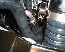 figure 11
 |
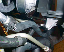
figure 12
return
to Table of Contents
|
|
Trailer Light Bulbs
return
to Table of Contents |
On 2003-06 Chevrolet Express and GMC Savana vans equipped with the trailer towing package RPO Z82, the additional electrical load from the trailer's turn signals and stop lights is handled by relays and not the turn signal/hazard flasher module. Refer to SI document 848202 for a wiring diagram.
Vans without RPO Z82 use a turn signal/hazard flasher module to handle the electrical load of the van’s turn signals and stop lights. Adding additional lights to this system may cause premature failure of the turn signal/hazard flasher module.
TIP: If an owner inquires about a trailer wiring harness for a van not equipped with
Z82, explain that the trailer cannot have more than one stop/turn bulb per side. If a trailer with more than one stop/turn bulb per side is connected, it may cause premature failure of the turn signal/hazard flasher module.
- Thanks to Ron Erman |
|
Headlamp Ballast
return
to Table of Contents
|
When servicing the headlamp ballast on a 2005 Corvette built between August and September, 2005, it is important to inspect the ballast before ordering and replacing with a new part. Some 2005 vehicles were built with a 2006 ballast. Ordering the 2005 ballast based on the parts catalog may not provide the correct ballast to fit the vehicle’s application.
Inspect the ballast to determine the number of mounting tabs, and order accordingly.
- Thanks to Dino Poulos
2005 ballast has 3 mounting tabs |
order 2005 p/n 12335922 |
2006 ballast has 4 mounting tabs |
order 2006 p/n 89025794 |
|
|
| Headlamp Fog |
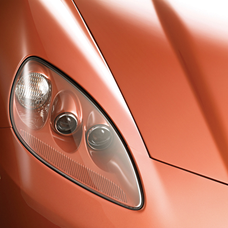
Owners of some 2005-06 Chevrolet Corvettes (fig. 13) may note that when the headlamps are on, light fog or cloudiness is visible on the lenses. Some customers may also state that the headlamp lenses have condensation or moisture.
The light fog or cloudiness is caused by out gassing of the clear polycarbonate lenses and is a normal characteristic of the vehicle. The headlamps are also vented; some condensation or moisture may be seen when humidity is high or there is a change in temperature. The moisture should burn off after one hour of headlamp operation.
Don't replace the headlamp lenses for the above concerns.
- Thanks to Paul Radzwilowicz
|

figure 13
return
to Table of Contents |
|
Axle Vent Hose Fluid Leak
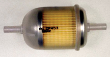
figure 14
return
to Table of Contents
|
This information applies to 2003-06 Chevrolet Silverado and Express, GMC Sierra and Savana, and Hummer H2.
An axle fluid leak that appears to be from the end of the axle vent hose most often occurs during hot ambient temperatures and/or while towing.
Installation of filter (p/n 5651682) (fig. 14) will act as an accumulator and prevent fluid from being forced out the end of the vent tube. Install the filter vertically in either direction approximately 10-15 cm (4-6 in) from the end vent cap of the hose or where convenient. Retain the filter using the supplied hose clamps and secure the filter and hose to prevent damage.
- Thanks to Rusty Sampsel |
|
Whine Noise from Speakers
return
to Table of Contents
|
Some owners of a 2006 Buick Rainier, Chevrolet TrailBlazer, GMC Envoy or Saab 9-7x may comment about a generator whine noise heard from the vehicle’s speakers. This will be noticed with the radio on or off, engine running.
This applies to short wheelbase vehicles equipped with UQA Bose Amplifier only. The amplifier on the short wheel base is located in the right rear quarter panel behind the trim. The harness is routed along the right side and follows the contour of the floor close to the sill plates. If the harness is not kept tight where the second row seat fastens to the floor, the harness may be pinched or trapped under the front corner of the second row seat frame or bolt.
Open the passenger rear door and remove the sill plate. Locate the harness that travels along this sill plate area and follow to the second row seat frame outer mounting bolt. If you suspect that the harness is pinched, remove the second row seat and remove the trapped harness. Repair any damaged wires and secure the harness to prevent damage in the future.
- Thanks to Dino Poulos |
|
| Brake Cooling Ducts |
The 2006 Corvette Z06 uses a duct on each side to carry cooling air to the front brakes. On early vehicles, the duct carried air rearward to an opening in the wheel liner
(fig. 15).
After VIN 1G1YY26EX65100198, a longer duct is used (fig. 16). It passes through the wheel liner and dumps air directly on the brake assembly.
One wheel liner is used with the short duct, and a different liner is used with the long duct. There are no service parts available for the short duct setup.
Regardless of which type of duct the vehicle originally had, if a replacement is necessary, the long duct and corresponding wheel liner must be used.
Here are the combinations of part numbers that must be ordered for the long duct and wheel liner.
|
Left Side |
Right Side |
Air Duct |
15829067 |
15829066 |
Wheel Liner |
15834373 |
15834374 |
Screw |
11514623 |
11514623 |
TIP: Some vehicles built before the VIN break may not have the duct fastener mounting holes in the frame. When necessary, these holes will have to be drilled and tapped for the M6 fastener (fig. 17).
- Thanks to Kiley Stites
|
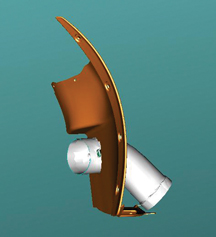
figure 15
|
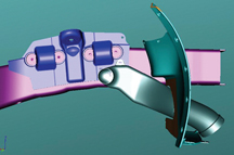
figure 16 |
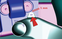
figure 17
return
to Table of Contents |
|
 Car Issues
— Fix It Right the First Time (new issues in bold) Car Issues
— Fix It Right the First Time (new issues in bold) |
Model Year(s) |
Vehicle Line(s) / Condition |
Do This |
Don’t Do This |
Reference Information/Bulletin |
2005 |
Chevrolet Corvette w/Navigation Radio – FM Radio Static or No Reception |
Have customer switch from FM to AM and back to FM. If this clears signal, no repairs required. |
Don’t replace radio and/or antenna module. |
05-08-44-014A |
2005 |
Cobalt, Pursuit (Canada Only) – CD Inoperative or Radio Displays “Locked” |
Reprogram U1C radio for “locked” message on control head. |
Don’t replace radio assembly. |
05-08-44-010B |
2005-2006 |
G6 w/Panoramic Sunroof – Potential Noise Issues |
Refer to bulletin. |
Refer to bulletin. |
05-08-67-014 |
2005 |
Corvette – Erratic Fuel Gauge |
Use new software release to add buffer to fuel sender system. |
Don’t replace fuel sender, fuel module or fuel tank. |
05-08-49-027 |
2005 |
Cobalt, Pursuit (Canada Only), ION, HHR – Transmission Control Module (TCM) Shorted to Battery Voltage During Diagnosis and/or Service |
Remove TCM harness from TCM prior to removing from TCM holding bracket. |
Don’t remove TCM from bracket without first disconnecting TCM wiring harness. Don’t allow TCM to contact positive battery post. |
05-07-30-016A |
2005 |
VUE, Equinox LT/LS – Sunroof will not Close from Vent, Partly Opened, or Fully Opened Position |
Replace sunroof control module. |
Don’t replace sunroof module, motor or switch. |
05-08-67-010A |
2005-2006 |
Uplander, Terraza, Relay, Montana SV6 – High Effort to Sound Horn, Horn Only Sounds When Certain Spots are Pressed |
Replace horn pad springs. |
Don’t replace inflatable restraint steering wheel module. |
05-08-54-001 |
2005 |
Grand Prix, LaCrosse/Allure – Front Brake Moan and/or Groan Noise During Brake Apply |
Confirm that noise is coming from front brakes – replace front brake pads. |
Don’t resurface front rotors. |
05-05-23-006 |
2004-2005 |
Grand Prix (June built 2004, all 2005), LaCrosse/Allure (all 05) – Blower Motor Inoperative or Intermittent, Blower Speed May Drop or Blower Continues to Run After Key Off |
Install 330MFD capacitor between LPM circuit to ground. |
Don’t replace LPM, blower motor or HVAC control head. |
05-01-39-001A |
2001-2003 |
Aztek, Rendezvous – Window Regulators Separate from Window Motors |
Use window regulator clips and procedure outlined in bulletin. |
Don’t replace window regulator assemblies that are serviceable and only have broken clips. |
03-08-64-015 |
1999-2004 |
All Cars and Trucks – Brake Warranty, Service and Procedures |
Issue One: Refinish brake rotor.
Issue Two: Measure for LRO |
Issue One: Don’t replace brake rotors.
Issue Two: Don’t measure for LRO |
00-05-22-002D |
2002-2005 |
Cars and Trucks – Multiple Driveability Symptoms/Clogged Fuel Injectors |
Clean fuel injectors as described in Bulletin. |
Don’t replace fuel injectors. |
03-06-04-030A |
|
| return
to Table of Contents |
|
|
 Truck Issues — Fix It Right the
First Time (new issues in bold)
Truck Issues — Fix It Right the
First Time (new issues in bold)
|
Model Year(s) |
Vehicle Line(s) / Condition |
Do This |
Don’t Do This |
Reference Information/Bulletin |
2002 |
TrailBlazers, Envoys, Bravada – Essential Tool for HVAC Mode Door Actuator Replacement |
Use GE-47676 to replace HVAC mode door actuator. |
Don’t replace cam assembly. |
05-01-38-001A |
2003-2005 |
SSR – Door Will Not Open From Inside Door Handle |
Replace door handle hinge support. |
Don’t replace door panel. |
05-08-64-026 |
2004-2005 |
Colorado/Canyon – Side Door window Glass Clips Fall Off |
Replace door window glass. |
Don’t re-attach door window glass clips. |
04-08-64-022 |
2001-2005 |
Chevrolet/GMC 36 Series Cab/Chassis – DTC P1172 or P2636, Fuel Gauge Reads Empty, SES Light On |
Modify fuel tank balance line. |
Don’t replace fuel tank unit, PCM or fuel transfer pump. |
05-06-04-008 |
2004-2005 |
All Cars and Trucks – State-of-Charge Upon Delivery of a New Vehicle |
Check battery’s state-of-charge using J-42000 or J-42000-EU. |
Don’t remove and replace battery. |
02-06-03-009A |
2002-2004 |
Silverado, Suburban, Tahoe, Sierra, Yukon/XL, Escalade EXT – Rough Idle, Misfire, MIL DTC P0300 |
Measure intake manifold for warpage across two runner ports only. Replace upper manifold gasket with teal-green gasket. |
Don’t measure intake manifold across all four intake runner ports. Don’t replace upper intake manifold gasket with orange gasket. |
05-06-04-029 |
2001-2003 |
Fullsize Pickups – Injector Replacement for High Flow Rates |
Use Bulletin 04-06-04-007A for injectors with high fuel return rates. Use Special Policy 04039 for all 01-02 vehicles. |
Don’t replace 8 injectors for any complaint other than high fuel return rates. All other injector failures are fix as failed. |
Special Policy 04039 |
|
| return
to Table of Contents |
|
|
|
Know-How Broadcasts for
MARCH |
| |
 |
| Know-How
Broadcasts for MARCH |
|
10206.03D Emerging Issues |
March 9, 2006
9:30 AM and 12:30 PM Eastern Time
|
|
New Model Features |
For Web NMF courses, log on to the GM Training Website www.gmtraining.com. Select Service Know-How/TechAssists from the menu, then choose New Model Features for a selection of courses. |
| -
Thanks to Tracy Rozman |
|
|
return
to Table of Contents |
|