| |

|
Note: Clicking
on any picture or illustration will open a larger version of that art.
|
|
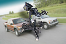
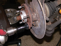
Pro-Cut
Brake Lathe |
GM Dealer Equipment
has begun shipping the new essential Pro-Cut PFM 9.2 Auto-Compensating
On-Vehicle Brake Lathe to all tier 1-4 dealers (franchise sales greater
than 100) who sell Chevrolet Colorado and GMC Canyon trucks (fig.
1).
TIP: Tier 5 dealers
will be required to sublet rotor turning on these vehicles to a facility
equipped with approved equipment.
Refer to bulletin 03-05-23-005 for details.
The Pro-Cut lathe performs brake rotor turning on-vehicle. It can be
used with both hubless and captured rotor configurations.
Explanation of Hubless vs. Captured Rotor
Until now, the typical GM car or truck has used a “hubless”
brake rotor. That is, the rotor is slipped onto the studs on the hub,
followed by the wheel. The wheel nuts clamp the rotor between the hub
and the wheel.
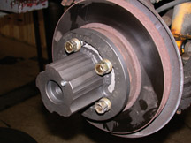
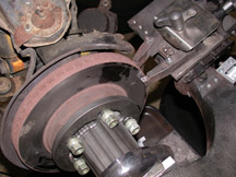
The Colorado/Canyon introduces a new brake design called “captured
rotor” (fig. 2). Here, the wheel
is mounted to the wheel studs on the front side of the hub, the same
as before. But the brake rotor is bolted to the back side of the hub
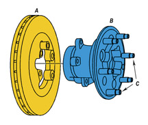
and is retained by separate fasteners (fig. 3).
A Rotor
B Hub
C Wheel stud
This affects rotor service in several ways.
1. Rotor removal requires removal of not only the wheel, tire, and brake
caliper, but also the hub/bearing assembly, which contains the ABS sensor
and wiring. Then the rotor is removed from the backside of the hub.
2. Once the rotor is removed, it is difficult to chuck onto a lathe
due to the large, irregularly shaped hole in the center (there is no
round center hole, as in hubless rotors). Bench machining may induce
lateral run-out, which requires replacement of the rotor.
3. Brake Align Correction Plates will not work with captured rotors.
For these reasons, captured brake rotors must be turned on-vehicle.
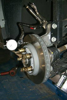
Brake Rotor Lateral Run Out (LRO)
TIP: Refer to
bulletin 01-05-23-001 and TechLink April 2001 for an explanation of
brake rotor lateral run out (fig. 4).
Excessive LRO results in intermittent contact between the brake pads
and rotor. Intermittent contact causes uneven rotor wear (thickness
variation), which causes the piston to pump in and out of caliper when
the brakes are applied. The customer senses this as brake pulsation
through the brake pedal. For this reason, GM has established a total
indicated run-out spec of 0.002-inch (0.050 mm) or less for all vehicles.
Using the Pro-Cut PFM 9.2
TIP: Purchase
of the Pro-Cut lathe includes set-up and training, plus a training CD.
The following is a summary only.
When performing on-car rotor turning, it is essential that the cutting
tools be properly oriented to the wheel hub centerline, to ensure that
LRO of the finished brake rotor is within specifications. The Pro-Cut
PFM 9.2 is auto-compensating, which means that the user does not have
to perform any critical set-up to ensure a high quality job.
Cleaning -- As with any brake job, on-car turning requires
that all mating surfaces be clean and free of corrosion. Use J-42450A
to clean the hub flange around the wheel studs (fig.
5), and use J-41013 to clean the hub/rotor mating surfaces.
Tool Installation -- Select the proper direct-fit adapter
from the four that are included with the Pro-Cut, attach to the vehicle
using the lug nuts, and torque properly (fig.
6). Attach the Pro-Cut to the adapter and tighten the retaining
knob.
TIP: When the
Pro-Cut is attached to the vehicle, it is supported by the vehicle’s
wheel hub. The Pro-Cut carriage is used only to hold the lathe when
not in use, and to assist in positioning the lathe to the wheel hub.
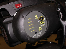
Auto-Compensation -- Run the built-in auto-compensation
routine. This aligns the lathe to the hub centerline, to ensure an accurate
cut. An indicator lamp tells when this has been accomplished (fig.
7).
Rotor Turning -- Take three scratch cuts to determine
the required depth of cut. The Pro-Cut is equipped with micrometer controls
(fig. 8). Once the cutters have been set,
run the Pro-Cut to automatically turn the rotor (fig.
9).
TIP: On vehicles
with rear disc brakes and limited slip differential, consult SI for
special instructions.
TIP: Non-directional
sanding is not required due to lathe performance.
Inspection -- Follow standard GM practices for measuring
LRO, using a dial indicator. The specification is 0.002-inch (0.050
mm) or less for all vehicles.
Wheel Torque -- Improper, uneven wheel lug nut torque
can cause rotor distortion, which undoes the careful work you’ve
done in finishing the brake rotor. (This is not a significant factor
of the captured rotor.) Follow standard GM practices for installing
wheel lug nuts. This requires a torque wrench or an impact wrench equipped
with J-39544 Torque Sockets.
TIP: Be sure
to index-mark the rotor and a wheel stud so the the rotor can be put
back in the same orientation, if it is removed for any reason.
For more information, be sure to watch the 10280.13D Technology Close-Up
-- Brakes Town Hall broadcast on January 29.
-
Thanks to Dave Roland, Jeff Hastings and Derek Trimble |
|
figure
1 |
|
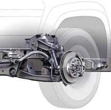
figure 2 |
figure
3 |
figure
4 |
figure
5 |
figure
6 |
figure
7 |
figure
8 |
figure
9 |
| return
to Table of Contents |
|
|
| REMINDER |
DealerWorld ID and Password -- U.S. service managers
and technicians are reminded to obtain individual ID and password from
your Partner Security Coordinator (PSC) for continued access to SI.
End of Support for Windows 98 -- Effective January
15, 2004, GMSO will no longer test TECHLINE software applications on
Windows 98SE, ME and NT. Dealers are strongly recommended to upgrade
with a full version of Windows 2000 Professional or Windows XP Professional.
Review the hardware specifications before buying software to ensure
the TECHLINE PC meets minimum specifications.
Refer to the December TechLink and GM Messenger communication for full
details.
-
Thanks to Mike Waszczenko and Lisa Scott |
|
|
|
| GMLAN
and Class 2 Difficulties |
Here
are some ways to avoid trouble when using the Tech 2 to communicate
with the GMLAN.
1. Be sure you have the current software installed on your Tech 2.
2. Perform the Tech 2 Cable Test before using the Tech 2 with the CANdi
module for the first time. This has been discussed several times in
TechLink (March 2003, August 2003 and December 2003) and also appears
on the TechLink website under the Reference Guide tab. This test permits
you to test the integrity of the Tech 2 and the cables.
TIP: Call TCSC
for help at 800.828.6860.
3. Before using the Tech 2 to communicate with the GMLAN (or Class 2,
for that matter), turn the ignition on and allow all controllers on
the vehicle to wake up (“boot up”). Otherwise, you may get
error messages from the Tech 2 such as “No Communication”
or “CANdi Module Not Detected”.
TIP: You can
be confident that all modules are awake by the time the IP warning lamps
and chimes stabilize.
4. Be sure to use the correct adapters. For instance, with the CANdi
module, you need to use p/n 3000098, which is a 16-pin adapter.
TIP: Do not make
the mistake of using the 71419 adapter from the old T50, T60, etc. Techline
terminals. Although it also has 16 pins, it is incorrect for this application.
5. Most problems experienced with the CANdi module setup result from
the cable or adapter, not the CANdi module itself.
TIP: For further
information on GMLAN, tune in to the IDL broadcast called GMLAN Electrical
Architecture and Functional Diagnostics 16048.20D..
- Thanks to Craig Jones and Mark Stesney |
| |
return to Table of Contents |
| |
| GM
TechLink in Its Sixth Year |
TechLink
began in September, 1998, as an occasional publication of the Service
Technology Group (which eventually became GM Service and Parts Operations).
During the first year, six issues were published. TechLink became a
monthly in October 1999.
TechLink owes much of its technical integrity to a dedicated group known
as the Editorial Advisory Board. At present, there are 14 members; over
the past five years, 20 people have served on the board. We’ve
even welcomed two summer college interns. For a photo of some of the
present members, check the Reference Guide
tab of the TechLink website at http://service.gm.com.
Also too numerous to mention are the many subject matter experts from
all over GM who have contributed story ideas, provided important data,
and reviewed stories for technical accuracy.
Some statistics -- You are reading the 58th issue of TechLink. Each
month, 68,000 copies are distributed to GM retail technicians, some
fleets, and within GM wholesale. And we’ve posted 35 issues on
the website, beginning in March 2001. The website is published in four
languages: English, Spanish, French and German.
Over the past five years, we’ve received numerous unsolicited
comments about TechLink from readers (mostly good!). And we’d
like to hear from you. If you have a comment, suggestion or even a criticism,
send them to:
mark.stesney@gm.com
jim.horner@sandycorp.com
-
Thanks to Bob Savo |
| |
| return
to Table of Contents |
|
| Service
Training Standards Requirements |
Beginning
January 2004, the Emerging Issues seminars become part of the Service
Training Standards requirements. Each dealership will be required to
participate in at least 6 of the 12 Emerging Issues seminars broadcast
in a given year. Dealers can meet this requirement by having either
6 different service technicians participate in distinct seminars, a
single service technician view all 6 seminars, or any combination of
the two. So long as 6 different broadcasts are viewed by service technicians
at a dealership, the dealership will receive a 100% toward meeting the
requirement.
-
Thanks to Tracy Timmerman |
| |
| return
to Table of Contents |
|
| 20-Inch
Accessory Wheels and Tires |
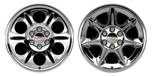
General
Motors has launched its collection of all-new 20-inch wheels, available
in forged or chrome finishes to reflect consumers’ personal styles.
The wheels were designed with a specific tire as part of the GM tire
and wheel system.
The accessory wheels and tires are suitable for installation on certain
1999-2004 Chevrolet Silverado and GMC Sierra pickups (fig.
10). Refer to bulletin 03-03-10-006
for specific details and exceptions. Here are the highlights.
TIP: Initially
the Wheel Launch Kit and required parts will be available in the USA
only. This program will be extended to Canada in 2004. Canadian dealers
must confirm availability of parts before utilizing this bulletin.
Designed with a Specific GM Vehicle in Mind -- Accessory
wheels from GM offer the best fit and function, and most tailored appearance
because they were designed to be an integral part of the vehicle architecture.
The new 20-inch tire and wheel assembly has been tested at GM’s
proving grounds in Michigan and Arizona.
Tires -- GM has created 20-inch wheels based on the
Goodyear Eagle LS P275/55R20 tire. This tire was designed to GM's Tire
Performance Criteria (TPC specification 1235 ms). GM's TPC specifications
meet or exceed all Federal safety guidelines.
Spare Tire -- Use a P265/75R16 or P265/70R17 tire mounted
on the vehicle's original spare wheel as a spare. The spare tire is
not intended for extended driving conditions.
Tire Changers -- Dealers must have the correct level of tire
changing equipment to perform tire changing services. GM requirements
and recommendations for servicing glamour wheels are in the bulletin.
For further information regarding equipment meeting the requirements
for this program, call 1-800-GM-TOOLS.
Balancing -- MC style coated weights are recommended.
If stick-on weights are used, follow the manufacturer's procedure (SI
Document 664222).
The tire and wheel assembly must be balanced on a computerized balancer,
capable of static and dynamic balance modes. Assemblies should be balanced
to within 1/4 ounce on either rim flange.
Center Cap -- Install the center cap onto the wheel after the
tire has been mounted and balanced, but BEFORE the assembly is installed
onto the vehicle. Push the cap in by hand. Alternately, use a nonmetallic
object to push the cap into place. Hammering may result in damage to
the cap.
Tire Pressure Monitoring (TPM) -- If the vehicle was originally
equipped with TPM sensors, transfer the original sensors to the new
wheels. Note the wheel location that the TPM sensor came from. Install
the new tire/wheel/TPM sensor assembly in the same wheel location that
the TPM sensor was originally. If the TPM sensors are not in the original
positions, you must reprogram the sensors.
Air Valve (Valve Stem) -- For vehicles without TPM,
use GM p/n 9593595.
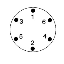
Wheel (Lug) Nuts -- TIP:
Aluminum wheels require special wheel nuts. Use GM p/n 9591772.
Torque each wheel nut in the appropriate sequence (fig.
11) to 190 Nm (140 lb ft). Re-check the torque after the first
160 km (100 mi). A wheel lock kit GM p/n 12497479 is also available.
Wheel Nut Caps -- After tightening the wheel nuts,
install the wheel nut caps finger tight, plus 1/2 turn. Black cap GM
p/n 15646250, bright cap GM p/n 88963146.
Jounce Bumper -- For 2WD vehicles, replace the existing
front suspension spring/jounce bumper with Jounce Bumper kit, GM p/n
12499481. Follow the procedure in the bulletin.
Re-Programming -- Reprogram the PCM for speedometer
accuracy. Contact Techline to obtain a VCI number (1.800.828.6860 English
or 1.800.503.3222 French). Then refer to the table in the bulletin for
the appropriate calibration part number, based on the model year and
axle ratio.
TIP: Because
this is not a warranty repair, dealers will incur a charge to obtain
a VCI number.
Update the tire size value in the ABS module, using the Tech 2. Follow
this path: Diagnostics > Model Year > Vehicle Type > Chassis
> Product Line > GVW > ABS > Special Functions > Tire
Size Calibration > Verify VIN > Select New Tire Size.
TIP: If original
equipment tires/wheels are later reinstalled, it will be necessary to
reset the programming of the PCM and the ABS module to the original
specifications.
Labels -- After installing the recommended P275/55R20
tires, place the provided tire inflation pressure and occupant/cargo
capacities label on the door jamb, near the original tire label. Do
not cover up the original tire label.
Warranty Information -- USA dealers should refer to
GM Warranty Administration Bulletin 00-03-10-003E and GM Parts Process
/ Policy Bulletin IB03-001 for more information.
Canadian dealers should refer to GM Warranty Administration Bulletin
01-03-10-003A.
Important:
Installation of these accessory wheels, tires and additional parts and
related procedures are entirely at customer expense.
-
Thanks to Mikael Hassler, Ann Briedis and Nina Price
|
figure
10 |
figure
11 |
| return
to Table of Contents |
|
| Dinghy
Towing Update |
This
information pertains to 2002-04 Envoy, TrailBlazer and Bravada.
The owner’s manual is being revised regarding dinghy towing (towing
the vehicle with all four wheels on the ground).
Early versions of the owner’s manual said to turn the ignition
to LOCK and remove the Ignition A and Ignition B fuses from the engine
compartment fuse block.
These vehicles do not have a LOCK position. The ignition should be turned
to OFF. There is no need to remove the ignition fuses because there
is no current draw in the OFF position.
Refer to the appropriate owner’s manual for complete procedures.
-
Thanks to Al Ferry |
| |
|
return
to Table of Contents |
|
| Winter
Cover |
This
information applies to trucks with the LB7 and LLY Duramax diesel engine.
A winter cover is included for use in cold weather states (fig.
12).
Installing the winter cover enhances heater performance and reduces
the amount of time it takes to warm the inside of the vehicle when the
temperature is below 0°F (-18°C).
The cover installs over the front bumper and restricts airflow to the
engine compartment.
Overheating Guidelines
The following guidelines apply, to avoid overheating the engine:
- Do not use when temperatures are expected to be above 32°F (0°C).
- Do not use when towing a trailer.
- Do not modify the cover.
Installation Tips
The vinyl cover may appear undersized before being fitted for the first
time. This is normal. It’s best to install for the first time
when the cover is warm.
The cover is retained by push-pins in the grille area, snaps, and black
tabs, which must be bent into a J-shape.
Cut the black stitches provided if a front license plate is required.
More information can be found in the owners manual on SI (document 837330).
Follow this path:
Build vehicle > Features and Controls > Starting and Operating
> Description and Operation > Winter Cover.
- Thanks to Steve Love |
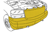
figure 12 |
| return
to Table of Contents |
|
| Evaporator
Case Water Intrusion |
A
potential water leak path from the evaporator case drain provision has
been identified on all 2001-04 Buick Rendezvous and Pontiac Aztek models.
Under certain high humidity and high ambient temperature conditions,
when the vehicle is driven for extended periods with low blower motor
speed, condensation moisture can reach the vehicle interior under the
carpeting. If an owner encounters this condition and water testing shows
no other cause for the water leak, install an extension elbow to reduce
the likelihood of reoccurrences. The part number recommended is 22542866,
which is used on other General Motors products.
The current plan is to utilize this part in production as soon as possible
and a bulletin will contain the breakpoints when the production change
occurs.
-
Thanks to Tom Russell
|
|
|
|
return
to Table of Contents |
|
| Steering
Wheel Controls |
Some 2003 and 2004 GM vehicles equipped with the OnStar system have
Steering Wheel Controls (SWC) that can be used in conjunction with the
OnStar Personal Calling Voice Recognition system.
Here is how the Steering Wheel Controls function on vehicles with OnStar
voice recognition and Steering Wheel Controls.
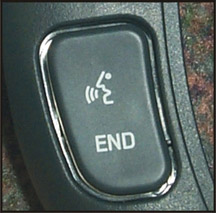
1. On the following vehicles, the push-to-talk button invokes the voice
recognition feature (fig. 13). A subsequent
press will re-invoke voice recognition for use with a voice mail system,
or other system which may require tones to be transmitted, such as dialing
an extension after reaching an office phone system. Saying the word
“dial” will transmit the tone(s) associated with the digits
entered. Subsequent presses of the button will re-invoke the voice recognition
system and the process repeats. Pressing the white dot button will exit
voice mode if a call has not been placed. To disconnect from the call,
press the white dot button or the "end" button on the steering
wheel.
TIP: If the vehicle
has NAV or the UV8 cell phone, these buttons function differently and/or
are disabled for OnStar functions. Consult the specific vehicle owner
manual for proper operation.
Seville, DeVille, Cadillac CTS, Cadillac XLR,
Cadillac SRX
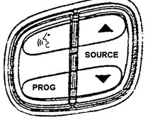
2. On the following vehicles, the push-to-talk button invokes voice
recognition (fig. 14). A subsequent press
will re-invoke voice recognition for use with a voice mail system, or
other system which may require tones to be transmitted, such as dialing
an extension after reaching an office phone system. Saying the word
“dial” will transmit the tone(s) associated with the digits
entered. Subsequent presses of the button will re-invoke the voice recognition
system and the process repeats. Pressing the white dot button will exit
voice mode if a call has not been placed. The user must use the white
dot button to end a call.
Escalade, Escalade EXT, Escalade ESV, Denali,
Denali XL, Yukon, Yukon XL, Tahoe, Suburban, Avalanche, Sierra Crew,
Sierra Ext, Silverado Crew, Silverado Ext, Hummer H2, TrailBlazer, TrailBlazer
EXT, Envoy, Envoy XL, Bravada, Envoy XUV, Rainier, Ascender
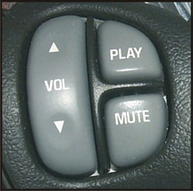
3. For the final group of vehicles, the mute button invokes voice recognition
(fig. 15). A subsequent press will re-invoke
voice recognition for use with a voice mail system, or other system
which may require tones to be transmitted, such as dialing an extension
after reaching an office phone system. Saying the word “dial”
will transmit the tone(s) associated with the digits entered. Subsequent
presses of the button will re-invoke the voice recognition system and
the process repeats. Pressing the white dot button will exit voice mode
if a call has not been placed. The user must use the white dot button
to end a call.
Aztek, Rendezvous, Century, Regal, LeSabre, Bonneville,
Grand Prix, Montana, Venture
4. The following OnStar equipped vehicles do not have steering wheel
controls for use with the voice recognition function. The voice recognition
function used for dialing an OnStar Personal Call is accessed using
the white dot button.
Cavalier, Sunfire, Colorado, Canyon, Venture,
Silhouette, Impala, Monte Carlo, Aurora, Ion, LS/LW, Malibu, Park Avenue,
Express, Savana, VUE
- Thanks to Steve Love and Jim Mikolaizik |
 figure
13
figure
13 |
figure
14 |
figure
15 |
|
return
to Table of Contents |
|
| Announcing
the 2004 Chevrolet Aveo |
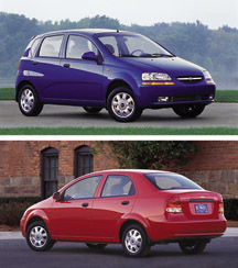
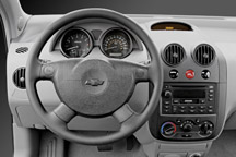
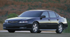
Chevrolet
has just introduced the entry-level Aveo (T200) subcompact four-door
and five-door sedan (fig. 16). Priced below
the Cavaliler, the Aveo provides Chevrolet dealers with a tremendous
opportunity to attract younger, first-time buyers.
All Aveo models feature Chevrolet's identifiable grille, with trademark
horizontal chrome mid-grille band and gold Chevy bowtie emblem. Additional
brand cues include a silver outlined bowtie on the center caps of the
standard steel wheels and a gold bowtie on the center caps of optional
alloy wheels, offered on LS models. The bowtie is also featured on center
pad of the steering wheel (fig. 17).
The Aveo is equipped with highly distinctive standard aerodynamic halogen
headlamps and amber side turn signal lamps. Fog lamps are also available.
P185/60R14 all-season steel-belted radials are mounted on either steel
or alloy 14-inch wheels.
The Aveo features a 1.6-liter dual overhead cam 16-valve inline 4-cylinder
engine that delivers 105 horsepower at 5800 rpm and 107 lb-ft of torque
at 3600 rpm. It’s teamed with either a manual 5-speed or automatic
4-speed transaxle.
The front suspension consists of McPherson struts with offset coil springs
and a stabilizer bar. The steering gear is mounted on a front suspension
cross member, to improve shock absorption for more precise and stable
handling.
The torsion beam axle mount compound link-type rear suspension is designed
to optimize driving performance when cornering.
All Aveos are equipped with a power-assisted dual diagonal brake system,
with discs in front and drums in the rear. A Delphi four-channel, four-sensor
ABS system (DBC-7) with Electronic Brake force Distribution (EBD) is
available.
Some Service and Pre-Delivery Tips
Aveo PDI service bulletin 03-00-89-040 explains several unique product
features. The information is useful for all technicians, not just the
PDI technician. Here are some highlights.
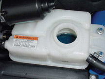
Coolant -- The Aveo cooling system is factory filled
with blue silicate/hybrid coolant (fig. 18)
and will be serviced with traditional green coolant. This type of coolant
must be drained, flushed and refilled every 30,000 miles (48,000 km).
Use P/N 12378560 (1 gal). In Canada, use P/N 993088 (1L) or P/N 993089
(4L).
Power Steering Fluid -- The power steering system uses
DEXRON® III fluid. Check the fluid level and adjust as necessary.
Use P/N 12378470 (1 qt). In Canada, use P/N 10952621 (500 ml) or P/N
10952622 (1L).
TIP: The use
of conventional power steering fluid in the system may lead to leaks.
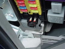
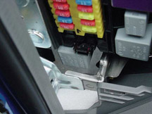
Fuse -- The radio/clock fuse is installed in a fuse
holder for shipping (fig. 19). The fuse
holder must be fully depressed toward the fuse panel and the fuse will
slide into place (fig. 20). This must be
done to ensure proper operation of the radio and clock.
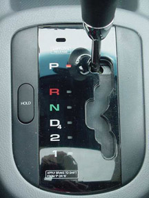
Automatic Transmission -- To move the automatic transmission
shift lever out of Park or Neutral, push down on the shifter knob (fig.
21).
When the HOLD button is depressed, the Hold indicator located in the
Secondary Information Center will light. There are two Hold mode features:
Winter Function -- When the vehicle is at a stop, depress
the hold button. The transmission will start off in third gear. This
will reduce the torque to the front wheels and will help the vehicle
maintain traction on slippery road surfaces.
Manually Controlling Shift -- When the vehicle is in
motion, depressing the Hold button will make the transmission operate
like a three speed transmission. You will be able to downshift the transmission
manually. The transmission will not shift into forth gear when the Hold
feature is activated.
The automatic transmission uses T-IV fluid GM P/N 88900925 (1 qt). In
Canada, use P/N 22689186 (1L).
TIP: Do not intermix
DEXRON® III fluid with the T-IV fluid.
Radio Code -- Each radio has a four-digit unlock code that must be entered
before the radio will operate. The code is located on a paper card inside
the glove box. Be sure the owner is aware of this code and remind them
to keep the code is a safe place. Any time the battery is disconnected,
COD will appear in the display, and the code must be entered into the
radio.
License Plates -- Aveos built before December 3, 2003
will not have the license plate fasteners placed in the glove box. Use
p/n 9423101 to fasten the license plate.
TIP: The cost
of the fasteners should be included in the net item column for the PDI
claim.
The Aveo doesn't use a front license plate bracket. There are four dimples
in the front fascia. The inboard dimples are the ones that should be
used to fasten the license plate. The outboard dimples are used for
European countries.
Tire Pressure -- The vehicle’s tires are shipped
inflated to 40 psi (276 kPa) and the pressure must be reduced to30 psi
(207 kPa). The tire pressure label can be found at the bottom of the
driver’s B-pillar.
Key Cutting
The accompanying chart outlines available key cutting equipment. Original
equipment key blanks for the Chevrolet Aveo are steel and are difficult
to accurately cut with hand-held key cutting equipment. Due to the risk
of mis-cutting high-cost Transponder and RKE key blanks with hand-held
key cutters, GM recommends using computerized duplicating/code cutting
equipment.
In addition, RKE and Immobilizer (Transponder) Keys require reprogramming
with Tech 2 after cutting. Refer to SI for detailed procedures.
- Thanks to Jeff Strausser |
figure
16 |
figure
17 |
figure
18 |
figure
19 |
figure
20 |
figure
21 |
| |
| |
GMDAT
Key Cutting Equipment
| Kaba
Ilco Computerized Code Cutting |
| Function |
Standard
Steel Blank |
Standard
Brass Blank |
All
Transponder or RKE Keys |
Part
Number |
Description |
|
|
|
| Computerized
Duplicating and Code Cutting |
Highly Recommended |
Highly Recommended |
Highly Recommended |
74-ULTRACODE
|
Ultracode Code
Cutter & Duplicator |
|
|
|
| |
| Kaba
Ilco Machine Duplicating and Code Cutting |
| Function |
Standard
Steel Blank |
Standard
Brass Blank |
All
Transponder or RKE Keys |
Part
Number |
Description |
Kit
(Required) |
|
|
| Machine Duplicating
and Code Cutting |
Available* |
Available* |
Available* |
74-029A-GM
|
Combo Key Duplicator
& Key Code Cutter |
74-029A-GMDAT |
|
|
| |
| Kaba
Ilco Machine Duplicating |
| Function |
Standard
Steel Blank |
Standard
Brass Blank |
All
Transponder or RKE Keys |
Part
Number |
Description |
|
|
|
| Machine Duplicating
|
Not Recommended |
Available* |
Not Recommended |
74-045-110VAC
|
Heavy Duty
Duplicator |
|
|
|
| |
| Kaba
Ilco Hand Held Code Cutting |
| Function |
Standard
Steel Blank |
Standard
Brass Blank |
All
Transponder or RKE Keys |
Part
Number |
Description |
Kit
(Required) |
|
|
| Hand Operated
Code Cutting |
Available* |
Available* |
Available* |
74-MK1-P26 |
Exacta Cutter
& Case |
74-MK1-GMDAT |
|
|
| |
| Curtis
Computerized Code Cutting |
| Function |
Standard
Steel Blank |
Standard
Brass Blank |
All
Transponder or RKE Keys |
Part
Number |
Description |
|
|
|
Computerized
Duplicating and Code Cutting
All Models |
Highly Recommended |
Highly Recommended |
Highly Recommended |
C9100021 |
PC+ Computerized
Code Cutter |
|
|
|
| |
| Curtis
Hand Held Code Cutting |
| Function |
Standard
Steel Blank |
Standard
Brass Blank |
All
Transponder or RKE Keys |
Part
Number |
Description |
Cam
Set (Required) |
Carriage
(Required) |
Code
Book (Required) |
Chev Aveo
Hand Operated Code Cutting |
Available* |
Available* |
Available* |
C-20791 (15XL-45)
C-20792 (15XL-47) |
45 Degree or
47 Degree Code cutter |
C21222 |
C21223 |
C21403 |
Chev Optra
Hand Operated Code Cutting |
Available* |
Available* |
Available* |
C-20791 (15XL-45)
C-20792 (15XL-47) |
45 Degree or
47 Degree Code cutter |
C21222 |
C21223 |
C21403 |
Chevy Epica
Hand Operated Code Cutting |
Available* |
Available* |
Available* |
C-20791 (15XL-45)
C-20792 (15XL-47) |
45 Degree or
47 Degree Code cutter |
C21222 |
C21223 |
C21403 |
| |
*
Original equipment key blanks for these vehicles are steel and
are difficult to accurately cut with hand held key cutting equipment.
Due to the the risk of "mis-cutting" high cost Transponder
and RKE key blanks with the hand held cutter, computerized
duplicating/code cutting equipment is highly recommended. Current
computerizied equipment will require software updates for GMDAT
vehicles.
Contact 1-800-GM-TOOLS (1-800-468-6657) for Ilco products or Barnes
Distribuiton (Curtis) 1-800-555-2878. |
|
|
| TAC
Corner |
Beginning
with this issue, the Technical Assistance Center (TAC) will be providing
administrative and Technical tips in the TAC Corner.
Access the most current information in SI (http://service.gm.com):
SI on the web is more current than using SI via the CDs. The SI web
is updated weekly on Thursday.
GM ACCESS is updated every second week, and requires the techincian
to process the update, at start up.
The stand-alone CD is updated once a month.
Be Prepared:
We have verified that some recent callers do not represent GM dealerships.
We need your assistance to help us confirm that the caller is a GM Technician
or Shop Foreman using GM supplied Service Information and is thus an
authorized caller. To accomplish this, we are asking that callers be
prepared with an SI document ID number that relates to the primary vehicle
concern of the call. This request applies to all vehicles produced from
1998 to present. This will also help us more quickly assist in diagnosis
and assure that the caller has properly researched the issue before
calling GM TAC.
Please perform all the necessary diagnostics and informational searches
before calling TAC. This allows us to serve you better.
Strategy Based Diagnosis (SBD):
The goal of SBD is to provide guidance when you create a plan of action
for each specific diagnostic situation. By following a similar plan
for each diagnostic situation, you will achieve maximum efficiency when
you diagnose and repair vehicles. Although each of the SBD boxes is
numbered, you are not required to complete every box in order to successfully
diagnose a customer concern. The first step of your diagnostic process
should always be the Verify the Customer Concern box. The final step
of your diagnostic process should be the Repair and Verify the Fix box.
Refer to the Strategy Based Diagnostics chart in SI. Use the keyword
“strategy”.
The guidelines for using Technical Assistance are in the P&P Manual,
Section 5.3.1. The sections cover:
1. Being Prepared -- follow SBD
2. Logging Calls
3. Closing a TAC Case
4. Returning a Survey Request
The forms for Technical Assistance are also available in this section.
- GM-TAF TAC Form
- TAC Case Call Log Sheet
- Diagnostic Worksheet
The worksheets help organize the call.
- Thanks to GM Technical Assistance |
|
|
| return
to Table of Contents |
|
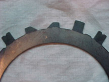
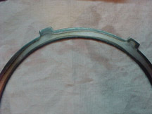
| Waved
Steel Clutch Plate |
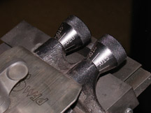
This
information applies to 4L60E/4L65E automatic transmissions.
On approximately November 1, 2003, a new heat treating process is used
for some transmission clutches. The Forward Clutch waved steel clutch
plate (648) appears dark in color, as if it were overheated at one time
(fig. 22). The Low/Reverse Clutch waved steel
clutch plate (682A) has a similar appearance on the inner and outer edges
(fig. 23).
Only the appearance has changed; the functionality of the clutches is
no different. These waved clutch plates will be used for both production
and service.
-
Thanks to GM Technical Assistance |
figure
22 |
figure
23 |
| return
to Table of Contents |
|
 Car Issues – Fix It Right The First Time
 |
Model
Year(s) |
Vehicle
Line(s) --
Condition |
Do
This |
Don’t
Do This |
Reference
Information / Bulletin |
2000-2004 |
Cavalier/Sunfire
-- Grinding Noise on Clutch Apply. Very low mileage |
Replace
clutch hydraulic line. |
Don’t
replace clutch/bearing |
03-07-31-005 |
1997-2004 |
Grand
Am / Alero / Malibu – Brake pulsation |
Turn
rotor and use brake align procedure |
Don’t
replace rotors for pulsation |
00-05-23-002
01-05-23-001 Know How #15040.01B) |
2003 |
DeVille
– No Crank / No Start |
Inspect
base of UBEC to ensure wire connectors are fully seated and not
loose. |
Don’t
replace PCM |
03-06-03-009 |
2001-2003 |
Venture
/ Montana / Silhouette/Rendezvous/ Aztek – Rattle or Buzz
from Exhaust System |
Install
clamp |
Don’t
replace Catalytic Converter |
03-06-05-003
dated 01/28/03 |
2004 |
Grand
Prix - Steering, Suspension or Cradle Click Noise. |
Re-torque
the Right Steering Gear Mount |
Don’t
replace the Steering Gear |
03-02-32-048
Dated 10/28/03 |
2000-2004 |
Impala/Monte
Carlo/Grand Prix - Headlamp Replacement for Condensation in Lamp |
Normal
condition when limited to fog or fine mist appearance in high
humidity conditions |
Don’t
replace headlamp assembly when no water droplets are evident |
01-08-42-001A
11/4/2003
Sept 02 TechLink |
2003-2004 |
CTS
– Variable Effort Steering (VES) “Service Steering
Message” DTC C1241 or C0450 |
Replace
VES solenoid only |
Don’t
replace entire steering gear |
03-02-36-001 |
2003 |
All
cars with 4T40/45E, 4T65E and 4T80E – Code P0742 |
Replace
TCC PWM
Solenoid |
Don’t
replace transmission or valve body assembly |
02-07-30-039B |
2002-2004 |
All
cars with 4T40/45E and 4T65E with DTC P0716, P0717 and other misc
codes |
Disconnect,
inspect, and reconnect transaxle wiring harness at the transaxle. |
Don’t
replace input speed sensor. |
02-07-30-022B(Oct
2003)
Sept 2003 Techlink |
2004 |
L61
EcoTech 4 Cylinder 2.2L Engine |
Replace
Spark Plug Sets |
Don’t replace PCM or Ignition Cassettes |
03-042
Recall |
|
| return
to Table of Contents |
|
|
 Truck Issues – Fix It Right The First Time
|
Model
Year(s) |
Vehicle
Line(s) --
Condition |
Do
This |
Don’t
Do This |
Reference
Information / Bulletin |
1993-2004 |
All Passenger Cars and Trucks – A/C Compressor |
Follow
SI and Bulletin for diagnostic information before replacing A/C
compressor. |
Don’t
replace A/C compressor. |
Service
VME, 10/31/03
01-01-38-013A |
1999-2003 |
Fullsize Pickups – Rear Spring Slap Noise |
Replace
inserts and rubber washers. |
Don’t
replace leaf spring. |
Service
VME, 11/17/03 |
1999-2004 |
GM Car and Trucks models with HomeLink Universal Transmitter –
Programming Diagnosis |
Use
J-41540 HomeLink Tester. Follow SI and refer customers to Owner’s
Manual. |
Don’t
replace HomeLink Transceiver without validating internal fault
recognized by
J-41540. |
01-08-97-001B |
2002-2003 |
All
TrailBlazers, All Envoys, Bravada – Squeak/Rub/Scrub Type
Noise in Steering Column |
Lubricate
and remove material, per bulletin. |
Don’t
replace upper or lower intermediate shaft. |
02-02-35-006A |
2003-2004 |
All TrailBlazers, All Envoys, Bravada, Rainier – Tail Lamp
Socket Circuit Board |
Replace
both tail lamp circuit boards |
Don’t
replace complete tail lamp assembly. |
Service
VME, 9/22/03
03-08-42-006A |
2003-2004 |
Fullsize
Pickups and Utilities – Servicing Wide Load Mirrors (RPO
DPF) |
Replace
individual parts as needed. |
Don’t
replace complete mirror assembly. |
03-08-64-028 |
2003 |
Fullsize
Pickups and Utilities – Transfer Case Service Light |
Replace
encoder motor sensor and reprogram TCCM |
Don’t
replace module, encoder motor or transfer case for DTCs C0327,
P0836, P0500 |
03-04-21-001B |
2003 |
Fullsize
Pickups – 6.6L Diesel Engine ECM |
Follow
SI and bulletins for proper diagnostics for P0181. Refer to the
Owner’s Manual (block heater and front cover) |
Don’t
replace ECM (DTCs P0540 and P0181) unless diagnostics confirm
need to replace |
02-06-04-048,
03-06-04-021, 02-06-04-058 |
2002-2004 |
TrailBlazer,
TrailBlazer EXT – Wavy Front Fascia |
Repair
fascia with Dual Lock |
Don’t
replace front fascia |
02-08-62-004 |
2002-2004 |
All
TrailBlazers, All Envoys, Bravada – Mirror Erratic Return |
Replace
mirror actuator and reprogram module |
Don’t
replace outside mirror assembly |
02-08-64-008
02-08-64-021 |
|
| return
to Table of Contents |
|
|
| Know-How
Broadcasts for February |
| |
 |
| Know-How
Broadcasts for February |
| 10280.02D
Emerging Issues |
February
12, 2004 |
9:00
AM, 12:30 PM,
3:30 PM
Eastern Time |
| 10280.14D
2005 Chevrolet Equinox |
February
26, 2004 |
9:00
AM, 12:30 PM,
3:30 PM
Eastern Time |
| -
Thanks to Tracy Timmerman |
|
|
| return
to Table of Contents |
| |
