|
 |
Note: Clicking
on any picture or illustration will open a larger version of that art.
|
|
Wireless
Headphones and Remote Controls |
Because the wireless
headphones and remote controls for GM DVD RSE (Rear Seat Entertainment)
and RSA (Rear Seat Audio) systems are loose
items, it’s possible for them to become separated from the vehicle
they’re intended for, before the vehicle is delivered to the
customer. In many cases, these items are not interchangeable among
vehicles. If the wrong components are provided to the customer, dissatisfaction
will result.
For example, a Chevrolet dealership will have three different remote
controls and they are not compatible (Malibu Maxx, TrailBlazer, and
Uplander). However, the headphones are compatible with all GM DVD systems
except the minivans, which require a 2-channel wireless headphone.
If the 2-channel headphones are used in the wrong vehicle, channel
2 (RSA) will not be audible, but channel 1 (DVD) will be audible.
To help keep these components straight, here’s some information
about the systems in use.
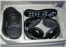
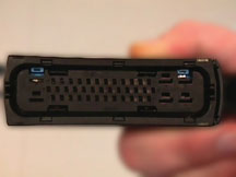
System 1a -- DVD RSE
The following headphone kit (p/n 15140532) is released for the 2005-07
Malibu Maxx only (fig. 1). The remote control will not work with any
other GM vehicles.
15140532 (Visteon) Headphone Package (DVD RSE) |
part number |
quantity |
item |
15762534 |
2 |
Headphone Assembly
(1 Channel Wireless ) |
22698894 |
1 |
Control Assembly - Video Player Remote |
15073730 |
1 Pack |
Battery Package - Headphone
4 - AAA |
15072561 |
1 Pack |
Battery Package - Video T/Player Remote Control
2 - AA |
22727857 |
1 |
Instruction - Video Disc Player Operation |
15140533 |
1 |
Instruction - Video Disc Player |
System
1b -- RSA without DVD RSE
TIP: The Malibu Maxx is the only current GM vehicle that offers an RSA system
with wireless headphones. The other GM vehicles have RSA systems which use wired
headphones (which are not provided to the customer).
The following headphone kit (p/n 10396845) is released for the 2005-07 Malibu
Maxx with RSA option (UK6)..
10396845 (Visteon) Headphone Package (DVD RSA) |
part number |
quantity |
item |
15762534 |
2 |
Headphone Assembly
(1 Channel Wireless ) |
15073730 |
1 Pack |
Battery Package - Headphone
4 - AAA |
System
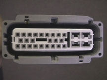
2 -- DVD RSE
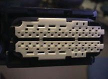
The following headphone kit (p/n 15072230) (fig. 2) is released for the 2005-06:
- Buick Rendezvous and Rainer
- Cadillac Escalade, EXT, ESV, SRX
- Chevrolet Avalanche, Silverado Crew Cab, Suburban, Tahoe, TrailBlazer
- GMC Envoy, Sierra Crew Cab, Yukon, Denali, XL, XL Denali
- Pontiac Aztek
- Saturn Vue
TIP: The remote control will work only in these GM Vehicles.
15072230 (Panasonic) Headphone Package (DVD RSE) |
part number |
quantity |
item |
01999421 |
2 |
Headphone Assembly
(1 Channel Wireless) |
01999355 |
1 |
Control Assembly - Video Player Remote |
15085989 |
1 Pack |
Battery package - Headphone
4 - AAA |
15085988 |
1 Pack |
Battery Package -Video T/Player Remote Control
2 - AA |
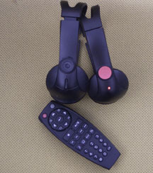
System
3 -- DVD RSE
The following two kits (p/n 15136091 and 15136092) are released for
the 2005-07:
- Buick Terraza
- Chevrolet Uplander
- Pontiac Montana SV6
- Saturn Relay
TIP: The remote control will work only in these GM vehicles. Channel
2 of the wireless headphones will work only in these vehicles (Channel
allows you to listen to DVD and Channel 2 allows you to listen to RSA).
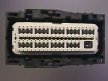
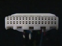
There are two DVD systems available:
- A base system U56 comes with a remote control kit only (no headphones
available).
- An uplevel system U42 comes with a remote control kit and a headphone
kit (fig. 3).
TIP: Headphone kit TX3 can be added to either system.
TIP: Batteries are not included.
15136091 (Hosiden) Headphones Only Package (DVD RSE) |
part number |
quantity |
item |
15185391 |
2 |
Headphone Assembly
(Dual Channel Wireless) |
15136092 (Hosiden) Headphones Only Package (DVD RSE) |
part number |
quantity |
item |
15190411 |
1 |
Control Assembly - Video Player Remote |
TIP:
If a kit is misplaced or was not shipped with the vehicle, follow
established procedures for misplaced/missing components. The service
part numbers for the kits are the same as the OEM part numbers.
- Thanks to Jeri Betts, Dwayne Hall and Matthew Marchiori |
|
figure
1 |
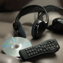
figure 2 |
| |
figure
3 |
| |
| |
| return
to Table of Contents |
|
|
| End
of Support for Windows 98, Millennium and NT 4.0 |
Attention: All Service Department Personnel
Beginning January 1, 2005, GM Service and Parts Operations will discontinue
ALL support for Windows 98 (Second Edition), Millennium and NT 4.0.
An announcement concerning the end of support was distributed to dealers
on October 31, 2003 under administrative message VMG20030999 (In Canada,
dealer communicatiion dated November 27, 2003). During this year, the
Techline Customer Support Center (TCSC) provided “one call limited
support” for the operating systems mentioned above. The one call
limited support will be discontinued on January 1.
For additional detail regarding supported operating systems and PC
hardware, go to http://service.gm.com/techlineinfo/techlinepc.html.
Review this document before making a business grade Techline PC purchase.
Questions regarding the information above can be directed to your local
Techline Consultant (TC) or the Techline Customer Support Center (TCSC).
TC contact information can be found on http://service.gm.com/techlineinfo/techlinepc.html.
TCSC can be reached at 1.888.337.1010, prompt 3. From Canada, 1.800.828.6860
(English) or 1.800.503.3222 (French).
- Thanks to Shawn Sullivan |
| |
| |
|
|
Daytime Running Lights Disable Qualifications and Process |
In
GM Service Operations’ continuous effort to provide the fastest
customer support possible, the following process is in effect for those
select governmental agencies that request and qualify for disabling Daytime
Running Lights (DRL).
TIP: In Canada, disabling of DRLs is not permitted by Transport Canada.
1. Only the following governmental agencies qualify for this disable
request: City/State Government, Police/Sheriff Departments, FBI, CIA,
DEA, and emergency vehicles if government owned.
2. All requests are to be made through the Techline Customer Support
Center (TCSC) at 1.888.337.1010.
3. The dealership will be required to obtain a letter on official agency
letterhead requesting the disable, stating that the agency owns the vehicle,
and stating the reason. The letter must indicate which features are to
be disabled. For example, both AHL and DRL disabled*. The letter must
include the specific VIN(s) of the vehicles which will be disabled and
this statement: “The DRL/Auto Headlamp system will be made fully
operational prior to disposal/sale of the vehicles listed above.” In
addition, the letter needs to be signed by a representative of the official
agency.
The letter must be kept in the service history file at the dealership,
and a copy sent to TCSC before the disable procedures will be released.
In most cases, the vehicles will require a software change that requires
a special VCI override.
* TCSC will make every attempt to honor these requests. In some cases,
it is not possible to disable a feature. Example: AHL disable is not
possible on 1999 and later S/T Trucks. Contact TCSC to see if disabling
the desired feature is possible on your specific vehicle.
-
Thanks to Abby Slagor |
|
return to Table of Contents |
|
| Important
Information About Programming a Replacement Module |
You
must begin by using your Tech 2 to obtain information from the vehicle.
Always follow proper procedures and precautions.
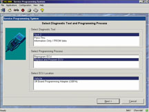
After selecting Service Progarmming Systems in TIS, you have a choice
between:
- Reprogram
- Replace and Reprogram
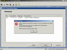
You now MUST select Replace and Reprogram (fig.
4). Then follow the remainder
of the standard procedure to install the data into the replacement module.
TIP: The default choice is Reprogram, and if you use it, you will receive
an ERROR message (fig. 5). If after following this procedure, you still
get the ERROR message, contact Techline Customer Support Center.
The Reprogram choice is used only to reprogram a module that will continue
to be used in the vehicle (installing the latest calibrations, for instance).
-
Thanks to Abby Slagor and Craig Jones |
figure
4 |
figure
5 |
| return
to Table of Contents |
|
| Top
Tier Gasoline Update |
Shell and Entec Stations
(Montgomery, AL) have been added to the Top Tier list.
These brands have been added to the running list on the TechLink website.
-
Thanks to Jay Dankovich
|
| return
to Table of Contents |
|
| MP3
Radio Software Upgrade |
This
information applies to 2005 Buick Rainier, Chevrolet Colorado, SSR,
TrailBlazer, and TrailBlazer EXT and GMC Canyon, Envoy, and Envoy
XL vehicles with MP3 (RPO US8) Radio CD Player. A software anomaly
within the radio has been found.
Some owners may comment that when playing a CD the radio displays the
last track number for about 5 seconds, but there is no audio. The display
changes to "READING" for about 15 seconds. Then it may play
the CD or eject the CD with a "CHECK CD" message.
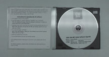
TIP: Each
dealership will receive the "2005 US8 MP3 Radio Software
Upgrade" CD through the Dealer World Delivery (DWD Box) process
the week of November 29th, 2004 (fig. 6).
TIP: This disc does not apply to Chevrolet Equinox.
Install the software upgrade CD into MP3 radio. Allow the software files
to transfer completely. This should take 1-2 minutes. This installation
should correct the condition noted above.
-
Thanks to Doug Daugherty
|
figure
6 |
return
to Table of Contents
|
|
| Synthetic
Oil |
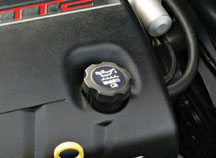
The following 2005 engines have synthetic engine oil installed at
the engine plant (fig. 7).
2.0L LSJ
3.6L LY7 Cadillac only
4.6L LH2
6.0L LS2
TIP: When
servicing these engines, use oil that meets the GM4718M specification,
as outlined in the Owners’ Manual. Not all synthetic oils will
meet this GM standard.
-
Thanks to Robert Stockwell |
figure
7
|
| |
|
| Pulse
Wiper Operation |
This
information applies to 2005 Chevrolet Cobalt (Pontiac Pursuit in
Canada) and Pontiac G6.
On these vehicles, there are three wiper modes: Pulse, Low and High.
In the Pulse mode, the wiper timing will fluctuate with the vehicle speed.
If the vehicle speed is below 50 mph (80 km/h), the wipers will take
up to 3 seconds between wipes.
TIP: In certain weather situations, if vehicle speed is below 50 mph
(80 km/h), the customer may find it necessary to switch the wipers to
the Low mode.
-
Thanks to Steve Oakley |
| |
|
|
| return
to Table of Contents |
|
| Tips
for Servicing .64 Terminals |
If
you’ve been following the various stories in TechLink about
electrical terminals over the past few years, you know that numerous
new types of terminal and connector systems have been introduced
(TechLink, Sept. 2002, June 2003, Feb. 2004).
One type of terminal, the .64, is offered by several suppliers, and there
are slight differences between them. The information here is intended
to clarify these differences.
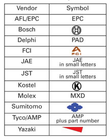
TIP: The
supplier of a system can often be determined by locating and identifying
the manufacturer’s symbol on the connector (fig.
8).
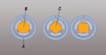
There are two different types or styles of male terminals that will mate
with the .64 female terminal (fig. 9).
A Stationary contact of female terminal
B .80 mm round terminal
C .64 mm square terminal
These are the .80 mm round style (Delphi and Bosch), and the .64 mm square
style (AMP/Tyco, Bosch, JST, Molex and Yazaki). The GM corporate intent
is to use only the Yazaki .64 terminal in the future. So you will see
more of this terminal in the future. A new crimp tool is being developed
that will crimp the Yazaki square and Bosch round .64 terminals.
TIP: It is not recommended to attempt to distinguish between the .64
terminal and the 100 terminal just by looking. The best way to be sure
is to use the .64 test probe (J-35616-64A) initially. If the J-35616-64A
probe seems obviously too small, move to the 100 sized probe.
If a male 100 terminal (or test probe, or anything incorrect) is inserted
into a .64 female, the .64 terminal may split. This destroys the terminal’s
retention capability. When that damaged .64 terminal is reconnected,
tension is too low to ensure proper contact and continuity.
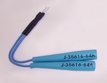
Test Probe
All of these connection systems use the J-35616-64A test probe. There
has been an update to this probe. The latest version has a blue wire
and a more robust silver terminal probe (fig. 10). Use the probe carefully
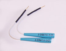
to avoid damage to the terminal.
TIP: The earlier probe has a white wire and a gold terminal probe (fig.
11).
TIP: The J-35616-64A and J-35616-65 test probes are correctly sized to
substitute for both the round and square male terminals.
Terminal and Connector Systems
The following paragraphs describe various terminal and connector systems
from several suppliers. One type to be aware of is the hybrid type, which
uses both .64 terminals and other sizes of terminals in the same connector.
It is assumed in all of the following that the connector wire cover,
if used, has been removed.
All of the following terminals are in the J-38125 Terminal Repair Kit
and in the tray indicated.
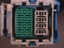
Delphi -- Many different Delphi connector shapes and styles are in use.
All Delphi .64 connection systems use terminal 15359541, which is found
in the Delphi tray 4. A Delphi Hybrid connector is shown in figure
12.
These connectors require the careful removal of the comb style TPA (Terminal
Position Assurance). They will break very easily if extreme care is not
used. Use the 15381651-2 terminal release tool pushed into the small
hole between two terminal cavities.
TIP: Do
not disassemble the Delphi connector body any more than removing the
TPA and in some cases, a nosepiece that covers the small terminal
release holes. It is very difficult to get all the terminals back into
place. If you do disassemble, you’ll have to remove all the terminals
and wires from the connector.
Reassemble the connector and then reinstall
the terminals and wires into the connector.
Watch for an expanded explanation of this in an upcoming issue of TechLink.
Molex -- A new Molex connection system is used on some ECMs. It uses
a square type .64 terminal number 33467-0003 or 33467-0005 depending
on wire size. Both are found in Delphi tray 23.
There is only one style of this connector in use so far (fig.
13). The
TPA surrounds the terminal area, and the color matches the ECM header
color. Lift the TPA up slightly to the preset position. Use the gray
J-38125-213 terminal release tool.
Insert it into the small hole in the
TPA next to the terminal you wish to remove. Once the new terminal has
been pushed back into position, press the TPA back into place.
Sumitomo -- A new Sumitomo connection system is used on some ABS modules.
It uses a square type .64 terminal 8100-3455 in the Sumitomo tray 22.
There is only one style in use so far (fig 14),
but others will follow. At first glance, this connection system looks
like it uses a terminal
larger than a .64. The whiteTPA surrounds the terminal area. Lift it
to remove. This is difficult and feels like it is going to break. Use
the green 12094429 terminal release tool. Insert it next to the terminal
you wish to remove and lift the plastic tang that holds the terminal.
Once the new terminal has been pushed back into position, press the white
TPA back into place.
Tyco -- Several Tyco systems are in use. One of them is used on the Medium
Duty Truck ABS module (fig. 15). It uses a square type .64 terminal 962885-5
in the Yazaki tray 15.
There is only one style of this connector in use so far. Use a small
screwdriver to move the two tabs of the blue TPA out slightly to the
preset position. Use the green 12094429 terminal release tool. Insert
it into the small rectangular hole next to the terminal you wish to remove,
moving the plastic tang that holds the terminal. Once the new terminal
has been pushed back into position, move the blue TPA back into place.
Another Tyco connection system is used on SDM modules (fig.
16). It uses
a square type .64 terminal. The service terminals in this connector are
the terminated leads 1393365-2-SIR in the new SIR tray. There is only
one style in use so far. Lift and remove the red TPA that surrounds the
terminal area. Use the black 15315247 terminal release tool. Insert it
next to the terminal you wish to remove and lift the plastic tang that
holds the terminal. Once the new terminal has been pushed back into position,
press the red TPA back into place.
A Tyco connection system is used on sunroof modules and other small modules
(fig. 17). It uses a square type .64 terminal 1123343-2 in the Lear tray
7.
There are several styles of this connector in use with different terminals.
You must carefully lift the white TPA on the top of the connector. Do
not remove. This TPA actually surrounds the terminal, so you will damage
it if you try to get it completely out. Use the green J-38125-24 terminal
release tool. Insert it next to the terminal you wish to remove and lift
the plastic tang that holds the terminal.
Once the new terminal has been
pushed back into position, press the white TPA back into place.
A Tyco connection system is used on the Transmission Control Modules
(TCM) of the Cadillac SRX, STS and CTS (fig. 18).
This connection system also uses a square type .64 terminal 2-1411578-2
in the Yazaki tray 15. Remove the strain relief (the cover on top of
the connector). Then, depress the lock tab on the side of the connector
and move one of two white TPAs aside to the pre-staged position. Insert
the green 12094429 terminal release tool into the small rectangular hole
next to the terminal you wish to remove. Move the plastic tang that holds
the terminal. Once the new terminal has been pushed back into position,
move the white TPA back into place. This connector is shown in the Wiring
Systems section of SI.
- Thanks to Jack Woodward and Guy Winohradsky |
figure
8
|
figure
9
|
figure
10
|
figure
11
|
figure
12
|
figure
13
|
figure
14
|
figure
15
|
figure
16 |
figure
17
|
figure
18
|
| return
to Table of Contents |
|
| Fuel
Filter Replacement |
Some customers have commented that they have been advised to replace
their vehicle’s fuel filter periodically.
On many vehicles, the fuel filter is non-serviceable (see table). The
filter is an integral part of the fuel pump module and fuel pressure
regulator assembly. The filter can be serviced only by replacement
of the fuel module assembly. This process requires the removal of the
fuel tank (one to two hours of labor, depending on the model), plus
several hundred dollars in unnecessary parts.
The vehicle owner’s manual outlines the periodic maintenance
service required, under the Maintenance 1 and Maintenance 2 guidelines.
Routine fuel filter replacement does not appear on either of these
schedules.
In the future, due to the increased regulation of evaporative emissions,
fuel systems utilizing a non-serviceable filter will become more common
as new models are introduced.
- Thanks to David MacGillis
| Vehicles with Non-Serviceable Fuel Filters |
| Chevrolet |
|
| 2003-05 |
Corvette |
| 2004-05 |
Malibu and MAXX, Silverado*, Tahoe**, Suburban, Avalanche |
| 2005 |
Equinox, Cobalt, Aveo, Trailblazer and EXT, SSR |
| GMC |
|
| 2004-05 |
Sierra*, Yukon** and XL |
| 2005 |
Envoy, XL and XUV |
| Pontiac |
|
| 2003-05 |
Vibe |
| 2005 |
G6, Pursuit ***, Wave*** |
| Buick |
|
| 2005 |
Rainier |
| Cadillac |
|
| 2004-05 |
XLR, Escalade, EXT and ESV |
| Hummer |
|
| 2006 |
H3 |
| Saturn |
|
| 2002-05 |
VUE |
| 2005 |
ION |
| *
2004 V8 only (4.3L uses conventional external filter) |
| **
2004 RPO L59 uses conventional external filter |
| ***
Canada Only |
|
| |
| |
Pontiac Vibe and Wave, and Chevrolet Aveo Fuel Filter
On the Pontiac Vibe, Pontiac Wave (Canada) and Chevrolet Aveo, the
fuel filter is serviced as part of the fuel pump module, as described
in the preceding paragraphs.
TIP: However, on these vehicles, if fuel pump module/fuel filter
replacement is required, it is not necessary to remove the fuel tank.
There is an access panel beneath the rear seat. When it's removed,
the fuel pump module can be removed. Refer to SI for details. |
|
|
return
to Table of Contents |
|
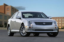
| Cadillac
STS Keyless Access System |
The STS (fig. 19) uses the same basic keyless system as the XLR (TechLink,
Feb. 2004) and Corvette (TechLink, Aug. 2004). The STS operates
at the same frequencies as the XLR and Corvette (315 MHz for
domestic, 433 MHz for Europe).
The STS may be susceptible to RF (radio frequency) interference or
EMI (electromagnetic interference).
This includes not being able to enter the vehicle or start the engine.
The driver can use the mechanical key or call OnStar to open the door.
But once inside, pressing the Start button may not start the engine.
Unnecessary Parts Replacement
These operating conditions are not a fault of the BCM, PCM, or other
control modules or components. Replacing them will not remedy the condition.
To help you understand what normal operation is, refer to the following
paragraphs.
Tips from the STS Owner’s Manual
TIP: The
STS owner’s manual explains the no-start condition under
the heading of NO FOBS DETECTED. Briefly it says the no-start condition
may be caused by equipment the driver has plugged into the accessory
power outlet in the center console. These could include cell phones
and chargers, two-way radios, power inverters, etc.
TIP: PDA devices and remote garage and gate openers may also interfere
with the keyless access transmitter. The owner is advised not to carry
the keyless access transmitter in the same pocket or bag as these devices.
TIP: Locations such as airports, automatic toll booths, and some gas
stations have fields which may interfere with the keyless access transmitter.
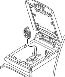
TIP: The owner is advised to move the transmitter to different locations
within the vehicle. If this does not help, place the transmitter in
the center console transmitter pocket with the buttons facing forward
(fig. 20) and then press the START button. If the vehicle battery is
sufficiently charged, this action will ALWAYS enable the vehicle to
start.
TIP: If the keyless access transmitter is not detected inside the vehicle
while trying to turn the ignition off, the NO FOB OFF OR RUN message
displays.
The vehicle may be near a strong radio antenna signal, causing the
keyless access system to be jammed. The vehicle will remain in ACCESSORY
until OFF or START has been pressed or 10 minutes has expired.
IMPORTANT: If the ignition is turned off and the keyless access transmitter
cannot be detected, the vehicle will not restart. The keyless access
transmitter needs to be detected inside of the vehicle in order for
the vehicle to start.
Multiple Fobs Present
Under certain circumstances, several people carrying valid keyless access transmitters
(fobs) may approach the vehicle at the same time. This will not affect door opening.
After the driver's door is opened, the driver preferences for the lowest driver
number will be recalled. Depending on which person’s fob is programmed
as Driver 1, the actual driver’s preferences may not be activated.
Battery Replacement
The vehicle will display a message when the fob battery is low. Until this occurs,
there are no effects on the system.
-
Thanks to Tobin Davis
|
figure
19
|
| 
figure
20
|
|
return
to Table of Contents |
|
| Fuel
Line Quick Connectors, revisited |
This
updates information originally in the February 2004 issue of TechLink.
Three styles of fuel line quick connects are now in use.
The TI Group© Global Quick Connector is used on C/K trucks, S/T
trucks, Malibu Sedan, Cadillac XLR, Chevrolet Cobalt, Saturn ION, Chevrolet
HHR, and the 2004.5 and 2005 Chevrolet Corvette (fig.
21).
The Legris© (pronounced “la-gree”) QC is used on Aztek,
Rendezvous, Venture, Montana and Silhouette and on the internal line
connection to the sender module on the Malibu Sedan (fig.
22).
The A. Raymond© (pronounced “a ramone”) QC is used on
the Malibu Maxx and on the Pontiac G6 (fig. 23).
Release
TI Group and Legris -- To release the quick connect, push on the retainer
using hand pressure only.
Push first toward the barb on the steel or plastic line, then pull the
quick connector off. Do not attempt to remove the retainer while the
connector is still attached to the mating line.
A. Raymond – To release the quick connect, put finger pressure
on both release buttons simultaneously. Push first toward the barb on
the steel or plastic line, then pull the quick connector off.
Do not use sharp or pointed objects to put pressure on the connector
retainer/release buttons. Using a tool may fracture the retainer, making
it less effective at keeping the connector assembled. It may be easier
to release the connector if it is first pushed toward the barb on the
mating line. If one attempts to release the quick connect while pulling
on the connector, the friction between the barb and the retainer will
make it difficult to release the quick connect feature.
TIP: Attempting to remove the retainer on the TI Group connector with
the line inserted will result in retainer breakage.
TIP: If a quick connect does not release with hand pressure, thoroughly
clean it and blow out grit and dirt with compressed air.
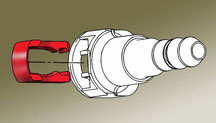
Repair
TI Group -- If the retainer is broken, it is not necessary to replace
the entire fuel line and attached component to repair it (fig.
24). Three
sizes of replacement retainers are available.
5/16-inch |
21992748 |
3/8-inch |
22717568 |
5/8-inch |
21992746 |
Legris
-- Replacement parts are not available for this retainer.
A. Raymond – Replacement parts are not available for this retainer.
- Thanks to David MacGillis |
| |
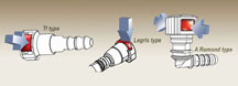
figure
21, 22, 23
|
| |
figure
24
|
| return
to Table of Contents |
|
| You
Can Review Know-How Videos on GM Training Website |
As
you know, new Emerging Issues and New Model Features programs are
broadcast monthly on the GM satellite network, according to the
schedule published on page 8 of each issue of TechLink. Repeat
programs are also broadcast throughout the month.
Because there’s a lot of information in these broadcasts, GM is
now providing you a way to review the material on the www.gmtraining.com website. At a designated time after Emerging Issues and New Model Features
broadcasts, the videos will be available on the website. You can use
this new web feature as an on-demand tool to recall information right
at the time you need it.
Keyword Search
An important feature of the website is the keyword search capability.
With it, you can pinpoint a specific video segment. You can even search
keywords in the sound track.
Logon Procedure
Here’s how to begin using these videos.
- Log on to the www.gmtraining.com website. You will need your personal
ID and password.
- In the menu, click on TECHAssist.
- Click the Service Know-How logo.
- On the video search page, you can launch a video program, or you can
search for specific content using the search parameters in the left window.
TIP: You can also launch a video from the online course catalog.
- Thanks to Steve Sternicki |
| |
| return
to Table of Contents |
|
| Creaking
or Popping Front Doors |
This
information applies to 2004-05 Chevrolet and GMC Full Size 2500HD
and 3500 trucks with the letter F in VIN position 11, designating
the Flint asembly plant. At this plant, between March and September,
2004, the torque guns used to attach the door check link to the pillar
were set to a low torque level.
Do not replace either check link or the door hinge to address this issue.
Remove the bolt, clean the threads and reapply Loctite® 242, GM p/n
12345382 (GM p/n 10953489 in Canada). Install the bolt and torque to
25 Nm (18 lb ft).
- Thanks to Jim Will |
| |
| return
to Table of Contents |
|
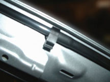
| Roof
Water Leak |
On
some 2005 Chevrolet Equinoxes with RPO CF5 (sunroof) or CE1 (OnStar),
water may leak from the headliner or map light. Here’s what
to look for.
On vehicles with OnStar, be sure the antenna is firmly secured. Run water
over the antenna to confirm it is not leaking.
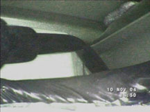
Next, check the condition of the sunroof drain hoses. Open the sunroof
and release the dual lock fasteners along the front edge. Carefully pull
the front edge of the headliner down to visually inspect the sunroof
drain hoses at the left and right front corners of the sunroof module.
The sunroof drain hoses must be pointing downward from the connection
to the sunroof module to ensure water can quickly drain away and to prevent
stress on the connecting joint. A stressed joint will slowly drip water
onto the headliner and this water can get to the map light. An incorrectly
positioned drain hose is shown in figure 25.
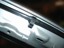
To correct the condition, remove the A-pillar trim on the affected side.
TIP: It
is not necessary to remove the headliner.
Release the hose from the mastic patch on the pillar and from the clip.
Gently pull the hose downward so the edge of the rubber portion can be
seated against the bottom side of the clip when reinstalled. Incorrect
hose installation is shown in figure 26 and correct installation is shown
in figure 27.
Confirm that the hose is pointing downward at the joint to the sunroof.
Then, securely seat the hose into the mastic patch.
Pour a small amount of water into the sunroof module area adjacent to
the drain connection. If leakage is evident, the hose may still be pointing
slightly upward.
TIP: It
may be necessary to remove the visor to give you more freedom of movement
to rotate or position the drain hose downward.
If the leak cannot be stopped, remove the drain hose and seal it to the
module.
TIP: It
may be necessary to remove the B pillar upper trim to get enough movement
in the headliner to access the drain hose for sealing.
-
Thanks to Ron Erman |
figure
25 |
figure
26 |
figure
27 |
| return
to Table of Contents |
|
| Headlamp
Switch |
After
replacing the headlamp switch on a 2003 full size truck or utility
you may notice the following changes.
1. The green and amber LED (light emitting diode) indicators are missing
from the face of the switch.
2. Trouble code B0951 will be set in the BCM after a replacement switch
is installed.
This is a normal condition. No repairs should be attempted.
A running change was implemented starting with the 2004 model year and
the new replacement switch doesn't have the "auto" and "disable" LED
indicators.
The BCM will store a trouble code B0951 when a replacement switch is
installed on a 2003 vehicle. This is due to the deletion of the LEDs
and will not change the operation of the DRLs and headlamps.
- Thanks to Paul Radzwilowicz
|
| |
|
return
to Table of Contents |
|
| Brake
Moan |
Owners
of some 2003-05 Chevrolet, GMC and Cadillac 1500 Utilities may comment
on a brake moan, hoot or fog horn type noise from the brakes.
This concern may be somewhat difficult to duplicate and happens only
after the vehicle is driven for a distance of 20-30 miles (32-48 km).
The noise is most audible when the brakes are applied between 20-40 mph
(32-64 kph) and the brake pedal is lightly released.
TIP: The noise may sound like it is from the front, when in fact it is
from the rear brakes.
Inspect the rear brake rotor surfaces for scoring or a grooving pattern
which may look like a vinyl phonograph record.
To correct this concern, machine the rear rotors and block sand the pads.
-
Thanks to Jim Will |
|
|
| return
to Table of Contents |
|
 Car Issues — Fix
It Right the First Time Car Issues — Fix
It Right the First Time |
Model
Year(s) |
Vehicle
Line(s) --
Condition |
Do
This |
Don’t
Do This |
Reference
Information / Bulletin |
1997-2005 |
Buick
Century, Regal – Broken
Armrest Lid Latch |
Replace lid latch
only. |
Don’t
replace console armrest lid (Regal) or front seat center
storage armrest (Century)
when only latch is needed to repair condition. |
03-08-49-018A |
2004-2005 |
Grand
Prix – Outside Rearview
Mirrors |
Replace mirror
glass or motor, whichever is defective. |
Don’t
replace complete mirror assembly. |
04-08-64-009 |
2004 |
Grand
Prix – Steering, Suspension or
Cradle Click Noise |
Re-torque right steering
gear mount. |
Don’t
replace steering gear or cradle. |
03-02-32-048 |
2000-2003 |
Century,
Regal, Lumina, Impala, Monte Carlo, Grand Prix, Intrigue with
3.8L L36 Engine – Coolant Leak |
Replace upper intake manifold
gasket only. |
Don’t
replace upper intake manifold assembly for coolant leak condition. |
03-06-01-016 |
2001-2004 |
Aztek
(01-04), Rendezvous (FWD, 02-04), Venture/Montana/Silhouette
(01-04) – Pop and/or Rattle in Exhaust Down Pipe |
Follow procedure in bulletin
using clamp P/N on down pipe to correct rattle/buzz noise. |
Don’t
replace converter assembly for rattle/buzz noise without completing
instructions in bulletin. |
03-06-05-003 |
2000-2004 |
All
Cars with 4T40/4T45E and 4T65E – Light
On/Various Transmission Codes Stores |
Check transmission 20-way
connector for secure connection (disconnect and reconnect). |
Don’t
replace transmission, TCC PWM, VSS, PCS or valve body. |
02-07-30-022B |
1998-2004 |
Seville – Heated
Seat Inoperative |
Replace only needed heating
element. |
Don’t
replace entire seat cover if heated seat element is inoperative. |
01-08-50-002C |
2000-2004 |
Cavalier/Sunfire/Alero/Grand
Am – Inoperative
Sunroof Module |
Retime module or replace
only motor for inoperative complaints. |
Don’t
replace entire sunroof module assembly. |
03-08-67-009A |
2003-2004 |
Cavalier/Sunfire – Air
Conditioning Compressor Noisy |
Inspect for ground out
conditions that can cause A/C compressor noise complaints. |
Don’t
replace A/C compressor for excessive noise complaint without
inspecting for ground outs. |
03-01-38-012 |
1999-2004 |
All
Cars and Trucks – Brake Warranty,
Service and Procedures |
Issue One: Refinish brake
rotor.
Issue Two: Measure for LRO |
Issue
One: Don’t replace the brake rotors.
Issue Two: Don’t measure for LRO |
00-05-22-002D |
|
| return
to Table of Contents |
|
|
 Truck
Issues – Fix It Right The First Time (new
issues in bold) Truck
Issues – Fix It Right The First Time (new
issues in bold)
|
Model
Year(s) |
Vehicle
Line(s) --
Condition |
Do
This |
Don’t
Do This |
Reference
Information / Bulletin |
2004 |
Tahoe,
Suburban, Silverado, Yukon, Yukon XL, Sierra, Escalade,
Escalade EXT, Escalade ESV, H2 – Passenger Door Module
and RKE Inoperative |
Re-flash
passenger door module. |
Don’t
replace passenger door module. |
04-08-52-005 |
2002-2004 |
Chevrolet
Silverado, GMC Sierra – Accumulator/Accumulator
Bracket |
Replace
accumulator and/or accumulator bracket. |
Don’t
replace compressor. |
02-01-38-007C |
2001-2003 |
Fullsize
Pickups – Injector Replacement for High Flow Rates |
Use
Corporate Bulletin Number 04-06-04-007A for injectors with
high fuel return rates. Use Special Policy 04039 for all 01-02
vehicles. |
Don’t
replace 8 injectors for any complaint other than high fuel
return rates.
All other injector failures are fix as failed. |
Special Policy 04039 |
2004-2005 |
All
Cars and Trucks – State-of-Charge
Upon Delivery of New Vehicle |
Check
battery’s state-of-charge
per revised PDI procedure using Midtronics Conductance Tester. |
Don’t
remove and replace battery. |
02-06-03-009A |
2002-2004 |
Fullsize
and Midsize Pickups and Utilities – Labor Operation
Assignments for Control Module Reprogramming |
When submitting claims
for reprogramming electronic module, use correct labor operation
that reflects module being programmed. |
Do not use K5364, which is for reprogramming
transmission control module (TCM), when reprogramming TCCM. |
02-04-21-006D
02-06-04-057D |
2002-2004 |
Fullsize
and Midsize Pickups and Utilities – Sleepy
New Venture Gear Transfer Case Control Module |
Verify sleepy module as
primary cause, per bulletin. Reprogram TCCM with latest software
released 3/11/04. |
Don’t
replace encoder motor or transfer case. Replace module only
if C0550 DTC shows as current or in
history. |
|
| 2002-2003 |
Chevrolet
Avalanche and Cadillac Escalade EXT – Cargo Covers
and Cladding Faded or Stained |
Thoroughly
clean, dry and treat components with “Armor-dillo.” |
Don’t
replace cargo covers for this condition. |
04-08-111-001A |
| 2002-2004 |
All Passenger
Cars and Trucks – Air Conditioner Compressor
Diagnosis |
Follow SI and bulletin for diagnostic information
before compressor replacement. |
Don’t
replace air conditioning compressor. |
01-01-38-013A
03-01-38-019 |
| 2002-2004 |
All
TrailBlazers, Envoy, Envoy XL, Bravada – Squeak/Rub/Scrub
Type Noise in Steering Column |
Lubricate and remove material,
per bulletin. |
Don’t
replace upper or lower intermediate shaft. |
02-02-35-006A |
2001-2004 |
Fullsize
Pickups and Utilities – Servicing
Wide Load Mirrors (RPO DPF) |
Replace individual parts
as needed. |
Don’t
replace complete mirror assembly. |
03-08-64-028 |
|
| return
to Table of Contents |
|
|
| Know-How
Broadcasts for February |
| |
 |
| Know-How
Broadcasts for February |
| 10290.02D
Emerging Issues |
February
10, 2005, 9:00 AM, 12:30 PM, and 3:00 PM Eastern Time |
| New
Model Features and Technology Close-Up seminars |
Stay
tuned! These programs will return soon. Check the Service
Know-How section of the GM Training website (www.gmtraining.com)
for more details. |
| -
Thanks to Tracy Timmerman |
|
|
| return
to Table of Contents |
|
