| |
|
|
Note:
Clicking on any picture or illustration will open a larger version
of that art.
|
|
Cylinder
Bore Liner Replacement |
A new tool EN-45680-850
has recently been released to replace cylinder bore liners in the
2.2L Ecotec four-cylinder engine (RPO L61 VIN
F or D).
Background
The cylinder block of the Ecotec engine is lost-foam cast aluminum
alloy, with pressed-in centrifugally-cast grey-iron cylinder bore liners.
In production, the liners are pressed into the block, then the deck
of the block and liners are machined all at the same time. The production
specification calls for the liners to be flush with the block, to +
0.02 mm (0.0008 in.) above deck.
The cylinder liner is beveled at the bottom end to help guide the liner
into the block bore. And the top of the liner is slightly flanged,
fitting into a counterbore in the block. This ensures that the liner
is properly seated when it is pressed into place.
Cylinder Damage
A cylinder bore of any engine can be damaged by a broken piston ring,
a loose wrist pin or clip, or piston debris caused by detonation damage.
The Ecotec is susceptible to the same kinds of hazards. In the Ecotec
engine, the liners are thin-wall castings, on the order of 1.5 mm (1/16-inch)
thick, so overboring is not a possibility.
Up until now, if a liner became damaged, it was necessary to replace
the entire engine assembly.
With the introduction of the EN-45680 L61 (L850) Cylinder Bore Liner
R & I Kit, it is now possible to replace a damaged liner. This
procedure can even be done with the engine remaining in the vehicle
on several vehicle product lines.
Although only the damaged liner(s) must be replaced, always inspect
all of the cylinders.
Detailed instructions are included with the tool kit, and are also
available in SI. These are the highlights.
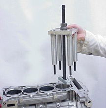
Liner Removal
The cylinder head must be removed, along with the piston and rod from
the affected cylinder(s). Follow SI procedures.
The fixture assembly is attached above the cylinder bore with previously-used
cylinder head bolts (fig. 1).
TIP: Cylinder head bolts must not be reused.
The fixture is installed from above, with the shoe positioned flat
against the bottom of the cylinder liner.
A nut on the puller is turned to pull the liner from the block.
TIP: Do not use any power tools to turn the removal tool nut, to avoid
damage to the block.
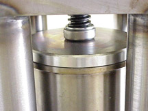
Liner Installation
After inserting a replacement liner into the top of the cylinder bore,
position the fixture above the cylinder bore and attach with the four
used cylinder head bolts.
An installation assembly is used to press the liner into place (fig.
2).
TIP: Do not use any power tools to turn the arbor screw, to avoid damage
to the liner.
When the liner is installed to within 1/16-inch (1.6 mm) of the block
deck face, use a torque wrench to tighten the arbor to specification.
When the flange of the liner seats into the counterbore of the block,
a minimal portion of the liner remains above the deck surface.
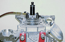
Liner Trimming
The kit includes debris plugs to be installed in the affected cylinder
and adjacent cylinder(s).
The service liner is very similar to the ones used in production. To
complete the installation, it’s necessary to machine the top
of the liner to production height specification, flush with the block
deck to + 0.02 mm (0.0008 in.) above deck.
It is also necessary to avoid damage to the block deck surface. This
requires proper setup of the cylinder liner trim tool.
TIP: Follow the instructions exactly to set up the cutting blades of
the cylinder liner trim tool, using the set gage ring supplied.
The cylinder liner trim tool is installed to the block over the affected
cylinder (fig. 3). An electric drill motor with specific power rating
and rpm must be used to operate the trimmer. And compressed air operates
the venturi vacuum that catches the metal shavings as the liner is
trimmed.
If multiple cylinder liners are being replaced, move the cylinder liner
trim tool and debris plugs from cylinder to cylinder as required.
Additional Information
The new tool was discussed at an Emerging Issues IDL broadcast on May
30, 2003. If you missed it, check the schedule for future re-broadcasts.
Also refer to bulletin 03-06-01-018 (June 2003).
-
Thanks to Ed Cheung and Joe Sraj |
| |
|
|
figure
1 |
figure
2 |
| |
figure
3
|
|
|
|
| Does
Your Dealership Have Enough Techline PCs? |
Today,
a Techline PC is just as important a service tool as a toolbox. All
Service Information (SI), as well as diagnostic and programming tools
(TIS), is accessed using the Techline PC. A Techline PC must be used
to ensure that all service repairs are fixed right the first time.
Many technicians waste critical time waiting in line or walking a
long distance to use their Techline PC. Imagine if a technician needed
to wait 10 minutes to gain access to his/her toolbox for each job,
every day. This wait time quickly adds up, and results in lost productivity.
The ideal ratio is 1 PC for every 2 technicians (1:2), which provides
the least amount of wait time to complete a job.
Recently, GM Service and Parts Operations teamed up with PC Source to
run a Multiple PC Pilot. Dealerships were provided with enough PCs to
meet the PC to Technician ratio (1:2) for a 90-day trial. These PCs were
new Techline-ready, Business grade machines. Each PC was connected to
the GM ACCESS network with wireless LAN cards, which eliminated the need
to install new hardwire for the network.
The dealerships evaluated the productivity gains from having the proper
equipment accessible to their technicians, and at the end of the 90 days
had a choice to purchase or return the equipment. Every dealership recognized
the initial cost of purchasing the equipment was quickly made up by faster
access to the most current service information. Every dealership purchased
the equipment at the end of the pilot.
A PC that meets the current PC Hardware Specification is now far more
competitive in price than it was 3 years ago. Your Techline consultant
can help with a Return on Investment (ROI) analysis to demonstrate how
quickly the ROI on a Techline PC purchase will be realized.
Fully integrated PCs are available through the PC Source at 1.800.233.0040.
Other PCs are available through GM Dealer Equipment at 1.800.GMTOOLS.
PCs from other vendors may be used, but must meet the PC Hardware Specification
located on http://service.gm.com. PCs that do not meet the Techline specification
may not work properly and will not be supported. Your Techline consultant
can provide additional help in deciding what is needed to maximize the
hardware in your service department.
- Thanks to Sam Hutson
|
| |
|
|
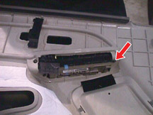
Reprogramming
Passenger Door Module
|
Owners
of some 2003 Chevrolet and GMC full-size pickups and utilities, Cadillac
Escalade models and Hummer H2 may have concerns that the RKE key fob
does not function, the front passenger door power window, lock, mirror
and heated seat are inoperative.
Affected vehicles fall into one of three categories:
- Those built before 01/03 -- refer to Bulletin 03-08-52-001C.
- Those built during 01/03 -- refer to Customer Satisfaction Bulletin
03-011.
- Those built 02/03 or later -- refer to published Service Information
for the symptom experienced by the customer.
TIP: Various names are used to describe the component involved in this
condition. The Door Lock and Side Window Switch contains a microprocessor
called the Passenger Door Module (PDM). The condition and repair procedure
involve the PDM.
Instead of replacing the Door Lock and Side Window Switch, you can now
refresh and reprogram the PDM using your Tech 2.
TIP: Your Tech 2 must contain software 23.001 (CD 3) or newer, released
March 8. If it does not, you must download this software before proceeding.
Depending on the vehicle’s build date, follow the procedure in
the appropriate bulletin to diagnose the conditions and refresh and reprogram
the module.
TIP: You MUST identify the applicable bulletin for the truck you’re
working on. And once you have identified the correct bulletin, you MUST
perform the procedures described in it, in the order given, and do not
skip any steps.
- Thanks to Doug Daugherty |
|
|
|
| return
to Table of Contents |
|
| Fuel
Gauge Erratic or Inaccurate |
This
information applies to 2001 S-10 and Sonoma Crew Cab Pickup models.
Refer to bulletin 03-08-49-003 for details.
On these models, the fuel gauge may be erratic, inaccurate, or go from
1/4 to empty too quickly. The cause may be an improperly calibrated fuel
gauge. The length of the float arm may also affect gauge operation.
The correction is to install a new fuel level sensor 25353298 and reprogram
the PCM with a new calibration. Call TCSC at 1.800.828.6860 (English)
or 1.800.503.3222 (French) for a VCI number to allow installation of
the new calibration.
-
Thanks to Dan Oden |
| |
| return
to Table of Contents |
|
| DTC
Master List |
When
diagnosing a vehicle, it may be helpful to know all of the DTCs that
pertain to the modules on that vehicle.
To obtain this list, go to SI on the web, and follow this path.
- “Build” the vehicle
- Service Manual/Bulletins
- Vehicle Control Systems
- Vehicle DTC Information
- Diagnostic Information and Procedures
- Diagnostic Trouble Code (DTC) List -- Vehicle
This will display a DTC list for that vehicle, including all possible
codes in categories B, C, P and U. Each DTC in the list is followed by
a brief descriptor of the circuit or component.
You can then print out the list for reference in your work area.
-
Thanks to Mark Haning |
| return
to Table of Contents |
|
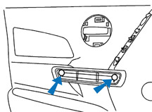
| Switch
Plate Bezel Removal |
This
is a reminder to follow the service procedure when removing the Switch
Plate Bezel from the front doors of 2000-04 full-size Pickups and
Utilities. Several door trims have been damaged by trying to take
out the bezel incorrectly.
TIP: You must first remove the door trim and the screw holding the bezel
in place.
TIP: Do not pry on the bezel from the top in an attempt to remove the
switch. The bezel and/or trim panel could be damaged.
Refer to SI documents 849812 and 849813 for the correct way to remove
the bezel.
1. Remove the front door trim panel.
2. Disconnect the electrical connectors.
3. Remove the screw that retains the switch panel bezel from the front
door panel (fig. 4).
4. Remove the switch panel bezel from the door panel using a flat-bladed
tool.
-
Thanks to Jack Cady and Mark Freigruber |
figure
4
|
| return
to Table of Contents |
|
| Parts
Restriction on PCM
|
The
2004 Pontiac Grand Prix is equipped with a new PCM. To provide feedback
and increased customer satisfaction, a parts restriction is in effect
through August 1, 2003. During this time, the PCM must be ordered
through TAC. When you call TAC, be prepared to provide Dealer Code,
VIN, mileage, RO number and results of diagnosis. Refer to bulletin
03-06-04-027A.
Returned parts will be analyzed by engineering to determine root-causes
of conditions. This information will help improve future products.
- Thanks to John Fletcher
|
| |
|
return
to Table of Contents |
|
| Timing
Tensioner Kit |
Owners
may comment about a noise coming from the engine between 1800 and
2200 rpm on some 1996-2003 Chevrolet and GMC trucks with the 4.3L
V6 engine.
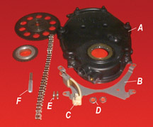
The rattle noise may be caused by torsional vibration of the balance
shaft. A timing chain tensioner kit has been released to deal with this
condition. The tensioner consists of a bracket which holds a nylon blade
against the timing chain.
Components are shown in figure 5.
A Front cover
B Tensioner bracket
C Nylon blade
D Washer
E Dowel pin
F J-46165 Pin Driver
TIP: The noise may resemble detonation or spark knock, which must be
ruled out before installing the tensioner kit.
Here are some of the highlights of the procedure. An upcoming bulletin
and an IDL broadcast will provide additional information.
The engine front cover must be removed for access to the crankshaft and
camshaft sprockets and chain. The camshaft chain must be removed. Depending
on model year, either the cam gear or crankshaft sprocket must be removed
to do this. Follow standard SI procedures.
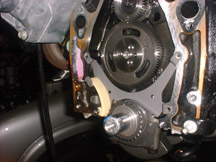
The tensioner bracket fits over four existing holes (fig.
6). The upper
two are the front cover center bolt holes. And the lower two are front
cover alignment holes.
TIP: The nylon blade must be temporarilly removed from the bracket.
With the tensioner bracket in position, use J-46165 Pin Driver to drive
dowel pins into the two bottom holes to retain the bracket.
Follow the bulletin procedure to complete the installation of the chain,
nylon blade and sprockets.
TIP: The kit includes two washers. Place them under the two center cover
bolts, which extend through the tensioner bracket. These are required
to maintain proper crush on the engine front cover seal.
-
Thanks to George Kaganac and Marty Case |
figure
5
|
| |
figure
6
|
|
|
| return
to Table of Contents |
|
| Terminal
and Connector Reference Guide |
If
you saw the Terminal Repair Kit Update article in the June 2003 issue
of TechLink, you may now have some questions about the proper way
to remove, install, and otherwise service terminals and connectors.
The answer is found on the internet, at the following address (no spaces
except as noted).
https://www.gmcommontraining.com/images/Terminals_and_Connectors_022003.pdf
This will provide you with the General Motors Terminals & Connectors
Reference Guide, 18043.05B. It’s a 56 page manual, offered in PDF
format. There are plans to update this Reference Guide as needed (fig
7).
TIP: If you do not have the necessary software to download a PDF, go
to www.adobe.com for a free version of Adobe Acrobat.
The manual includes several subsections. In Standard Terminal Replacement,
you will find:
- crimp tools
- splice crimp tools
- splice clip application
- visual inspection standards
- and more.
In Terminals and Connectors, you will find Delphi connector identification
and Yazaki connector identification. The information is presented using
full-color illustrations.
Connectors
- photos
- terminal position assurance lock (TPA), if equipped
- location of the entry canal for insertion of the removal tool
Replacement Terminals
- photos
- part number(s)
Removal Tools
- photos
- tool number
- Kent-Moore J-number
Crimper Tools
- photos
- tool number
- Kent-Moore J-number
For convenience and future reference, you may print your own copy of
this manual, using your computer’s Print function.
- Thanks to John Roberts |
|
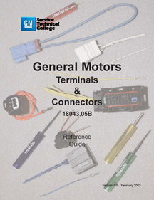
figure 7
|
| return
to Table of Contents |
|
| Availability of Electrical Terminals |
According
to parts bulletin IB03-044, a select group of terminals are no longer
offered by GM Parts, but are available directly from SPX Kent-Moore.
38 part numbers are affected.
-
Thanks to GMSPO |
| return
to Table of Contents |
|
| TransFlow Heater Blanket |
Kent-Moore
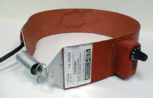
has just released an optional accessory (fig.
8) for the J-45096
Transmission Oil Cooler Flush and Flow Testing Kit (TechLink, Jan.
2003).
To review, the TransFlow equipment has two major functions: (1) to use
Dexron III automatic transmission fluid (ATF) to flush the transmission
oil cooler and lines, and (2) to accurately perform a flow test to identify
restrictions.
The Heater Blanket J-45096-10 fastens around the TransFlow’s internal
supply vessel. When plugged into a 110 v AC supply, the blanket will
heat ATF in the supply vessel to at least 65° F (18° C). This
is the minimum required operating temperature.
TIP: Below 65° F, the TransFlow will shut itself off. Below this
temperature, it is difficult to accurately measure the flow of ATF.
TIP: Allow extra warming time when you replenish fluid in the supply
vessel. Remember, it holds 31 quarts.
A special feature of the blanket is the thermostat, which will maintain
a set temperature.
TIP: Heating blankets without temperature control (typical freon heating
blanket) could affect the electronics in the TransFlow equipment.
To order, call Kent-Moore at 1.800.345.2233.
-
Thanks to Dan Popoff and Rick Mills |
figure
8
|
| return
to Table of Contents |
|
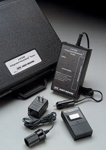
| HomeLink® Test
Kit |
The
Homelink Wireless Control System has been available on numerous GM
passenger cars and light duty trucks since 1995. It provides remote
operation of garage doors, estate gates, home lighting, and other
home automation devices, using a 3-channel transceiver built into
the vehicle.
The J-41540-GM Transmitter Test Kit (fig. 9) is an essential tool which
is useful in diagnosing the system.The kit includes a HomeLink Tester,
a Hand Held Transmitter, and a 120V-to-12V power supply. The Tester may
be operated from the vehicle’s accessory outlet or from the kit’s
power supply.
Complete instructions are supplied with the test kit, and you should
follow them when performing the tests. Proper testing and diagnosis can
help eliminate unnecessary replacement of parts. Here are some highlights.
Functionality Test
The Functionality Test establishes:
- That the Tester (receiver) from the kit is functioning.
- That the Hand Held Transmitter from the kit is capable of transmitting.
- That HomeLink is getting power from the vehicle.
- That HomeLink can be placed in the Default Mode This is a special mode
used only for testing. It is not the same as the Training Mode used by
the customer to program HomeLink to operate different devices.
- That HomeLink is capable of transmitting.
The instructions explain how to perform each of these tests and what
to do in case of a failure.
Range Test
The Range Test establishes:
- That the signal from HomeLink extends from the vehicle for a distance
of 15-30 m (50-100 ft.).
The instructions explain how to perform the test and what to do in case
of a failure.
Training Test
The Training Test establishes:
- That HomeLink is capable of being trained (programmed), in this case
using the Hand Held Transmitter from the kit.
- That the trained HomeLink is capable of operating the appropriate device
(in this case, the Tester from the kit) from a distance of 15-30 m (50-100
ft.).
The instructions explain how to perform each of these tests and what
to do in case of a failure.
TIP: Garage door openers manufactured before 1982 may not be compatible
with the HomeLink system. The fact that HomeLink passes the test procedure
does not guarantee that it will work with an older system. A universal
receiver or fix kit (for some older systems that were not manufactured
before 1982) is available for purchase at www.homelink.com or by calling
1.800.355.3515.
Once you have used the test kit to establish that HomeLink is functioning
properly, be sure the owner understands how to train HomeLink, using
their own hand held transmitter for the device they are programming.
TIP: You may offer to train HomeLink for them, using the customer’s
hand held transmitter, as a special service. If you successfully train
the hand held transmitter to HomeLink, it doesn’t guarantee that
the device will operate when they return home. Some garage door openers
and gates are equipped with rolling codes. The customer will need to
perform additional steps for HomeLink to activate these devices.
To determine if HomeLink has learned a rolling code, press the HomeLink
button. If the LED flashes rapidly for 2 seconds, then turns solid, additional
programming steps are needed.
Owners who require special programming assistance, who want to purchase
HomeLink accessories or learn about compatible products, may call 1.800.355.3515,
or visit the website at www.homelink.com.
TIP: A dealer
specific website is also available at www.dealerlink.homelink.com.
-
Thanks to Kobie Glenn and Marci Brogan |
figure
9
|
| return
to Table of Contents |
|
| Tool
Numbering System Changed |
See
bulletin 03-00-89-005 for details. Here are the highlights.
Effective immediately, all new essential and available tools will be
numbered according to a global numbering scheme.
TIP: Existing J-numbered tools will not be re-numbered.
Each tool will be placed in one of six categories according to function:
|
Category |
GE |
General, including HVAC |
EN |
Engine |
DT |
Transmission, differential |
CH |
Chassis |
EL |
Electrical, including SIR |
BO |
Body, frame, trim |
The two-character
function code will be followed by a five-digit number sequence:
EN-12345
As before, an alpha suffix indicates a revision:
EN-12345-A
A numerical suffix indicates a part of a kit:
EN-12345-1
TIP: Use the first two characters to help you organize your new tools. -
Thanks to Dave Roland and Derek Trimble
|
| return
to Table of Contents |
|
| P-Codes
with Warranty Claims |
The
OBDII (On-Board Diagnostics) system is capable of providing a great
deal of diagnostic information when vehicles are repaired because
the Malfunction Indicator Lamp (MIL) is illuminated. You are requested
to pass along as much of this information as possible.
Technicians -- On the repair order, record the OBDII P-codes, technician
observations, and customer comments. (GM Service Policies and Procedures
Manual, article 1.6.2)
Warranty Claims Administrator -- Enter the same information in the comment
section on the warranty claim for submission. (GM Claims Processing Manual,
Section 4.2.g)
This information is continually analyzed by GM Powertrain Engineering.
This process will provide engineers with accurate, detailed information
on a more timely basis. The idea is to identify and resolve potential
product concerns as early as possible.
If you will provide P-codes, your observations, and customer comments
on every vehicle you repair for an OBDII related code, Engineering can
begin to better understand what is causing the MIL to illuminate.
The inclusion of P-codes on repair orders varies from year to year. In
2002, 36% of repair orders did not include P-codes. So far this year,
it’s dropped slightly to 32%. But there’s still a lot of
room for improvement. Engineering asks for your cooperation.
-
Thanks to Kiet Nguyen |
| return
to Table of Contents |
|
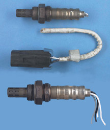
| Proper
Removal of O2 Sensors |
This
reminder applies to all vehicle lines and model years, and is about
proper oxygen sensor removal techniques. Some of the oxygen sensors
returned to the Warranty Parts Center have been damaged during removal,
which means they cannot be analyzed (fig. 10).
There are a variety of special tools and slotted sockets available for oxygen
sensor removal which will not damage the pigtail. If space allows, a crowfoot
wrench is also appropriate. A suitable tool is needed for installation of the
new sensor. Using it for removal as well will eliminate damaging the wires on
the sensor being removed.
The rate of damaged O2 sensors returned for analysis has been cut in half so
far this year. Engineering appreciates your help and asks that you continue to
take care not to damage them during removal.
-
Thanks to Kiet Nguyen |
figure
10 |
| return
to Table of Contents |
|
| Door
Trim Panel Removal |
When
removing the door trim panel on the 2004 Grand Prix, do not use a
standard socket to remove the hexhead screws located in the pull
handle of the front or rear door trim panels. Some of the tubes are
too narrow and the standard socket, when pushed down onto the screw
will split the plastic tubes (fig. 11).
A thin walled 10 mm socket must be used. Early production vehicles use
a screw with a hex head. Later production vehicles have a screw that
has a combination of hex head and Torx head. This screw can be removed
with either a thin walled 10 mm socket or a T30 Torx head driver.
-
Thanks to Mel Spresney |
figure
11
|
| return
to Table of Contents |
|
| Transmission
Shift Conditions |
Owners
of some 2002-2003 LeSabres, Park Avenues and Bonnevilles may experience
no transmission upshifts, erratic shifts, and/or slipping from the
transmission. This condition may be caused by a poor electrical connection
inside of the underhood fuse box or Bussed Electrical Center. The
terminal that feeds the tranmission fuse may be spread too large.
TIP: If you discover a deformed terminal, follow SI procedures to replace
it.
On the LeSabre and Bonneville, the terminal at connector C3 pin E7 is
at fault. On the Park Avenue, connector C2 pin E4 is the faulty terminal.
The DTCs are P0753 and P1860.
-
Thanks to Bill Metoyer |
| return
to Table of Contents |
|
| Electrically
Folding Mirrors |
There
are some misunderstandings about the operation of RPO DL3 mirrors
on 2003 full size pickups and utilities (fig
12).
The mirrors in this option can be folded inboard electrically (when entering
a car wash, or parking in a confined space, for instance) using the same
switches normally used for adjusting the individual mirrors. Place the
L/R toggle switch in neutral. Then use the pad to fold the mirrors in
or out.
These mirrors must always be moved electrically. If a mirror is folded
inward manually, and then moved back outboard manually, the mirror will
not latch into the detent. The result is that the mirror may move and/or
shake.
TIP: If the mirror displays these conditions, simply cycle the mirror
inboard and back outboard using the electric controls. This will cause
the mirrors to click into the proper detents.
New vehicle prep technicians should be made aware of these procedures
and should verify proper operation of the mirrors before delivery.
TIP: Be sure the customer also understands mirror operation.
-
Thanks to Steve Love |

figure
12
|
| return
to Table of Contents
|
|
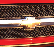
Grille
Bowtie
|
The
Chevrolet front grille bowtie emblem on 2000-03 Tahoe and Sububurban
(new body style) or 2003 Silverado may peel, delaminate or not properly
adhere. This emblem can be serviced by ordering just the bowtie (fig.
13) and not the entire front grille.
TIP: The upper grille baffle must be removed to replace the emblem. Refer
to SI document 1327886 for the procedure.
The service part number for the 2003 Silverado bowtie emblem is 12335700.
The service part number for the Tahoe and Suburban bowtie emblem is 12335633.
Parts are currently available from GMSPO.
-
Thanks to Doug Daugherty |
figure
13 |
| return
to Table of Contents |
|
| Performance
of XM Radio System with Sunroof |
Owners
of 2003 Chevrolet Monte Carlo and 2004 Pontiac Grand Prix may experience
poor XM signal reception with the sunroof fully opened.
Because the sunroof travels over the XM antenna at the rear of the roof,
the signal may be blocked. This is a characteristic of this antenna and
sunroof system.
This statement is contained in the vehicle owners manual. “Your
XM Satellite Radio antenna is located on the roof of your vehicle. Keep
this antenna clear of snow and ice build-up for clear radio reception.
The performance of your XM system may be affected if your sunroof is
open.”
TIP: Suggest that the customer move the sunroof forward enough to allow
the XM signal a direct line from the satellite/repeater to the antenna.
-
Thanks to GM Technical Assistance |
| return
to Table of Contents |
|
| Wire
Harness Stretched |
Affected
Models:
98-02 Buick Century, Regal, Park Avenue, Le Sabre, Chevrolet Monte Carlo,
Venture, Oldsmobile Intrigue, Aurora, Silhouette, Pontiac Grand Prix,
Bonneville, Montana
98-99 Buick Riviera, Oldsmobile Eighty Eight
98-01 Chevrolet Lumina
01-02 Chevrolet Impala, Pontiac Aztek
02 Buick Rendezvous
On the listed vehicles, the 4T65E Pressure Control Solenoid (PCS) wire
harness may be stretched, or the PCS may not be oriented in the same
position, after installing a service replacement valve body assembly.
TIP: The service valve body casting is different from the original casting.
The casting difference does not affect operation.
There is a small tab on the pintle end of the solenoid windings. Bend
this tab in slightly toward the pintle. DO NOT remove it. Bending the
tab inward will allow the PCS to rotate in the bore and orient the connector
in the same position as the original PCS. This relieves the wire harness
strain.
-
Thanks to GM Technical Assistance |
| return
to Table of Contents |
|
| Water
Leak in Front Floor Carpet Area |
Affects
1998-2003 Chevrolet S-10 and Blazer, 1998-2001 Oldsmobile Bravada,
1998-2003 GMC Sonoma, 1998-2001 GMC Jimmy (US), 1998-2003 GMC Jimmy
(Canada Only), 1998-2001 GMC Envoy
Some of the above vehicles may have a mildew odor or wet carpet in the
front passenger seat area. Here are the most common causes and cures.
- Water backing up at the plenum drain
Too much sealer at the plenum drain area can act as a dam, allowing water
to back up in the plenum and either seep around the air box seal or around
the lower right air box mounting screw. If a plenum drain has a ridge
of sealer higher than 1/4 inch (6.4 mm), use a utility knife to cut the
sealer down to 1/4 inch (6.4 mm) in height.
- Voids in the plenum seam sealer
Use a mirror to examine the inside of the plenum for possible voids in
the seam sealer where water can gain entry to the passenger compartment.
Seal any voids using the procedures listed in the service manual.
- HVAC recirculation door being left open
The HVAC recirculation, or air box, door opens upward when the HVAC conrols
are set to MAX A/C. In extreme conditions, water can pool on top of this
door and spill into the vehicle. This door can remain open if the HVAC
mode is set to MAX A/C when the ignition key is cycled off. Customers
should be informed of this condition and should be advised to turn the
HVAC setting to the regular A/C or OFF position before turning the vehicle
off.
TIP: Water may still leak into the passenger compartment, even with the
recirculation door in the fresh air position. This may occur in extreme
conditions (heavy downpours, etc.). Check for a hole above the air box
(between the two threaded holes that retain the right front fender) for
proper sealing. This hole should be sealed if found not to be sealed
properly.
To prevent water leaking into the passenger compartment(s), even under
heavy downpour conditions, fabricate a small plastic dam, 3/4 inch (19
mm) high x 3 inches (76 mm) long, then glue and seal it to the recirculation
register under the recirculation door. This will allow small amounts
of water (1/4 inch (6.4 mm) to 1/2 inch (12.7 mm)) to puddle in the HVAC
case without entry into the vehicle.
- Door harness boot
Water that is found in either the driver or passenger floor at the A-pillar
may have entered at the door harness boot on the A-pillar side. Make
sure the boot harness if fully seated in the A-pillar.
- Plenum/Cowl/Instrument sub panel (windshield tray)
Water may enter at the three piece Plenum/Cowl/Instrument sub panel.
This area must be sealed from the inside of the vehicle; the dash assembly
must be removed to gain access. This area can be sealed by spraying a
clear sealer (KENT brand) in a gallon commercial sprayer, up under the
Plenum/Cowl/Instrument sub panel.
IMPORTANT: Please follow these diagnosis processes thoroughly and complete
each step. If the condition exhibited is resolved without completing
each step, the remaining steps do not need to be performed. If these
steps do not resolve the condition, please contact GM TAC for further
diagnostic assistance. This diagnostic approach was developed for the
vehicles listed and should not automatically be used for other vehicles
with similar symptoms.
-
Thanks to GM Technical Assistance |
| return
to Table of Contents |
|
| Clunk
Noise Felt Through Floor Pan |
Affected
Models:
1998-2003 Chevrolet S-10, Blazer
1998-2001 GMC Envoy, Sonoma, Jimmy (US), and Oldsmobile Bravada
1998-2003 GMC Jimmy (Canada)
Some owners of the listed vehicles may experience a clunk noise that
can be felt through the floor pan
This condition may be caused by the torsion bar crossmember contacting
the frame rails during left or right turns or on uneven surfaces.
Determine if the clearance between the left frame rail to crossmember
and right frame rail to crossmember are equal. If not, install either
a washer or alignment shim between the upper mount and frame.
Refer to SI document 539243. This document includes a component diagram
of the torsion bar crossmember to frame rail assembly and may provide
assistance in the repair.
-
Thanks to GM Technical Assistance |
| return
to Table of Contents |
|
| Radio
Buzz, Pop, Static, or Whine Noise From Any Speaker |
Vehicles
equipped with non-class 2 amplifier (RPO UQ7, w/o Y91) may have no
volume or speaker buzz, whine, distortion, pop, or static noise coming
from any speaker.
Inspect the center console wire harness, approximately 5 inches (12.7
cm) from connector C306 toward the amplifier connector, for excessive
twisting. If the harness has excessive twisting, the bare drain wire
(ckt 2011 or 2099) may cut into the low level audio signals and cause
this concern. Repair the harness as necessary.
-
Thanks to GM Technical Assistance |
| return
to Table of Contents |
|
 Car
Issues – Fix It Right The First Time Car
Issues – Fix It Right The First Time |
Model
Year(s) |
Vehicle
Line(s) --
Condition |
Do
This |
Don’t
Do This |
Reference
Information / Bulletin |
2001-2003 |
3800
L36 -- Coolant leak at intake manifold |
Replace
the intermediate (upper) intake gasket |
Replace
the intake manifold assembly |
Bulletin
in process
VME to field 5/30/03
Techlink article |
2003 |
CTS
-- “Service Stability System” DTC C1286 |
Reprogram
EBCM |
Replace
steering wheel position sensor |
02-05-25-004 |
2000-2003 |
Cavalier,
Sunfire, Grand Am, Alero, Malibu – Fuel gage accuracy and
pump concerns |
Replace
sensor card for fuel gauge accuracy issue |
Replace
the fuel sender / pump assembly |
01-06-04-008D |
1999-2003 |
Grand
Am / Alero – Door glass clip breakage |
Replace
sash clip only |
Replace
entire door glass assembly for broken clips |
01-08-64-018 |
1997-2003 |
Grand
Am / Alero / Malibu – Brake pulsation |
Turn
rotor and use brake align procedure |
Replace
rotors for pulsation |
00-05-23-002
01-05-23-001
Know How 15040.01B |
1997-2003 |
Venture
/ Montana / Silhouette – Windshield water leaks |
Use
correct diagnosis procedures described in service bulletin |
Assume
that leak came from the windshield sealing |
01-08-57-006 |
1997-2003 |
Century
/ Regal – HVAC “Auto” light function |
Normal
in full heat or cold setting |
Replace
HVAC control head for "Auto" light |
99-01-39-007B |
1999-2002 |
Corvette
- Fuel gauge goes to empty intermittently |
Install
revised software |
Replace
fuel senders or I/P cluster |
2002
Bulletin
02-06-04-010,
1999-2001 Software released bulletin not yet updated |
2003 |
All
cars with 4T40/45E, 4T65E and 4T80E – Code P0742 |
Replace
TCC PWM Solenoid |
Replace
transmission or valve body assembly |
02-07-30-039B |
2002-2004 |
L61
EcoTech 4 Cylinder Engine |
Replace
Cylinder Bore Liner |
Replace
Engine |
03-06-01-018 |
|
| return
to Table of Contents |
|
|
 Truck
Issues – Fix It Right The First Time Truck
Issues – Fix It Right The First Time
|
Model
Year(s)
|
Vehicle
Line(s) --
Condition
|
Do
This
|
Don’t
Do This
|
Reference
Information / Bulletin
|
2003
|
C/K
Fullsize Pickups & Utilities -- Transfer Case Service Light
|
Replace
Encoder Motor Sensor, Reprogram TCCM
|
Replace
Module, Encoder Motor or Transfer Case For DTCs C0327, P0836,
P0500
|
03-04-21-001B
|
1999-2002
|
C/K
Fullsize Pickups & Utilities -- Throttle Body
|
Clean
throttle body adjust blade and insert plugs
|
Replace
throttle body for idle instability or pedal effort
|
02-06-04-054B & Parts
Restriction
|
2003
|
C/K
Fullsize Pickups
6.6L Diesel --Engine ECM
|
Follow
SI & Bulletins for proper Diagnostics; P0181 refer to Owner’s
Manual -- Block Heater and Front Cover
|
Replace
ECM (codes P0540 & P0181) unless Diagnostics confirm need
to replace
|
02-06-04-048
03-06-04-021
02-06-04-058
Parts Restriction
|
2003
|
C/K
HD Silverado, Sierra, G Savana, Express >8600GVW -- ABS Lamp
On
|
Re
flash for code C0550
|
Replace
ABS module
|
TIS
2000: 4.0
Service VME
|
2002-2003
|
Envoy,
Envoy XL, Bravada, with G67m -- Low in Rear
|
Replace
check valve service kit
|
Replace
air suspension compressor
|
02-03-99-001
|
2002-2003
|
TrailBlazer,
TrailBlazer EXT Envoy, Envoy XL, Bravada -- OS RVM Erratic Return
|
Replace
mirror actuator & reprogram module
|
Replace
OSRV-mirror
|
02-08-64-008
02-08-64-021
|
1999-2003
|
C/K
Fullsize Utilities - Sunroof
|
Install
clip or mechanism kits
|
Replace
sunroof
|
02-08-67-009
|
1999-2003
|
C/K
Fullsize Pickups & Utilities -- Noise on Steering
|
Lube
I-Shaft
|
Replace
I-Shaft
|
00-02-35-003B
|
1999-2003
|
TrailBlazer,
Envoy, Bravada,
without G67 -- Moan Boom
|
Replace
rear coil springs
|
Repurchase
vehicle for rear axle vibration/boom noise
|
02-03-09-002A
|
2002-2003
|
TrailBlazer,
TrailBlazer EXT, Envoy, Envoy XL, Bravada -- Tail Light
|
Replace
tail lamp circuit board
|
Replace
rear tail lamp assembly, for brake light
|
Service
VME to use service part, listed in GMSPO catalog
|
|
| return
to Table of Contents |
|
|
| Know-How
Broadcasts for August |
| |
 |
| Know-How
Broadcasts for August |
|
10270.08D
Emerging Issues
|
August
14, 2003
|
9:00
AM, 12:30 PM,
3:30 PM
Eastern Time
|
|
10270.20D – 2004
Buick New Model Features
|
August
23, 2003
|
9:00
AM, 12:30 PM,
3:30 PM
Eastern Time
|
| -
Thanks to Tracy Timmerman |
|
|
| return
to Table of Contents |
|
|
|
