| |

|
Note: Clicking
on any picture or illustration will open a larger version of that art.
|
|
New
Pre-Delivery Inspection Form Introduced |
A new Completely
Satisfied Delivery System program (CSDS) will be rolled out with the
introduction of the 2005 Cadillac STS. The CSDS is the system the salesperson
uses to introduce the customer to his/her new vehicle. Among its new
features is an orientation to the service department.
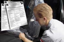
Accompanying the CSDS is a revamped Pre-Delivery Inspection Form (fig.
1).
The new form places a stronger focus on areas affecting customer satisfaction
and JD Powers scores, it reduces redundancies with other upstream inspections,
and creates a more robust PDI process.
Ensuring that quality pre-delivery inspections are done will improve
initial quality and customer satisfaction. Enhancements have been made
to the pre-delivery inspection process to help improve initial quality.
The intent is not to reduce or increase the time allotment for dealers
to perform PDI.
The refined form was the result of considerable research. GM studied
11 competitive manufacturers’ forms and evaluated common and unique
characteristics.
Early customer feedback data (JD Power IQS2 and Zero Day Warranty) were
reviewed for areas of focus and potential adds to PDI.
Assembly Center “CARE Line” items were investigated, and
redundant inspections were eliminated at the dealer level.
As a result of the investigation, 20 checks were deleted, 15 checks
were added, and 18 changes were made to the wording on the form.
Here are highlights and explanations of some of the changes. JDP focus
areas are indicated by an asterisk (*).
- The form now provides a place to record tire pressures after checking
them.
Some vehicles are shipped with higher tire pressure, to ensure proper
bead seating and to resist the effects of shipping.
TIP: Tire pressure
affects ride quality. Ride quality is an important JDP focus area (*).
- Battery check and charge are added to ensure that the dealer begins
storage with a fully-charged battery. Battery maintenance is the dealer’s
responsibility while the vehicle is in dealer stock.
- Reset the fuel economy reading (*).
The initial fuel economy reading is affected by the way the vehicle
is driven before delivery. Vehicles may be run very hard during dynamic
vehicle testing at the plant, then driven slowly around the plant and
dealer premises before delivery to the customer. By re-setting just
before delivery, the customer gets a truer reading of their actual economy
(*).
- Check for wind noise (*).
- Clean the wiper blades using Optikleen. This helps alleviate windshield
wiper chatter concerns (*).
- Erase voice recorder messages.
- Check OnStar for connectivity.
It’s important to check this, because some plants do not have
the capability to connect with OnStar. Also, some plants can successfully
connect to OnStar, but a successful connection cannot be made at the
dealer location. In most instances, this is a correctable concern.
TIP: The OnStar
check is a simple push of the OnStar button during the road test.
- Perform additional checks for squeaks, rattles and noises.
- Check for water leaks.
- Verbiage is clarified in the brakes portion of the road test.
- Steering check is added to the road test.
-
Thanks to Chris Anderson |
|
figure
1 |
|
|
| return
to Table of Contents |
|
|
| Daily
Updates for SI |
In late June, GM Service and Parts Operations announced that the SI
website is now updated daily rather than weekly to include Service Manuals,
Bulletins, Campaigns and PIs. The daily updates will occur Monday through
Friday.
The GM ACCESS server update will continue to be broadcast on Monday.
-
Thanks to Larry Quinn |
|
|
|
|
PDI -- Leather Seats |
Significant
numbers of customers are expressing concerns in surveys about dirty
seats in new vehicles at delivery. This is primarily in vehicles with
leather seats, and the driver’s seat is most often cited.
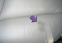
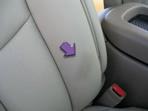
Seats show coffee stains, ink marks, grease marks and dirt in general
(fig. 2, 3, 4). Soiling may be caused by
drivers during transport from the assembly plants, by customers during
test drives and vehicle evaluations, or by dealership personnel moving
the vehicles while at the dealership.
Regardless of the cause(s), seats must be inspected as a part of the
pre-delivery inspection, and cleaned as necessary before delivery.
TIP: The owner’s
manual recommends a soft cloth moistened with mild soap and water.
TIP: The Pre-Delivery
Inspection form (see accompanying article) calls for removing protective
coverings from the interior just before delivery. This is intended to
minimize soiling of the upholstery.
- Thanks to Saundra Massingille |
|
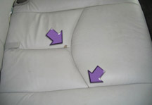
figure 2 |
figure
3 |
figure
4 |
return to Table of Contents |
|
| Divisional
Shows for Emerging Issues |
Based
on audience feedback, the Service Know How Emerging Issues broadcast
for US dealers will undergo a three-month trial of divisional-based
shows. These shows will allow for a more-focused presentation of information
for technicians, as well as minimizing training time. Feedback for this
type of show format will help determine whether division-based segments
will continue, return to the previous programming, or develop new directions
to better keep technicians informed of the latest developments.
TIP: The broadcast
times for July, August and September will now be 12:30, 1:00, and 1:30
PM.
Starting in July, 2004 and running through September, 2004, Emerging
Issues will be split into 3 segments:
- 12:30 - 1:00 PM Pontiac, Buick and GMC
- 1:00 - 1:30 PM Chevrolet Cars and Trucks
- 1:30 - 2:00 PM Cadillac and Hummer
The live broadcast will be available only once during the day. There
will not be a 9:00 AM or 3:30 PM show.
The course number will remain the same, as the three segments are all
part of the same show. There will be three tests associated with each
monthly show, one for each segment.
Technicians can take the test that is specific to their dealership segment.
The test will still be available on the GM training website. The STS
reporting will not change; there is an ongoing requirement for participating
in 6 out of the 12 seminars.
SKH Emerging Issues will remain available for General viewing and shows
will be repeated on a weekly basis.
-
Thanks to Tracy Timmerman |
| |
| return
to Table of Contents |
|
| Before
Replacing an SDM |
When working on an air bag system, if you see a DTC B1001, do not replace
the Sensing and Diagnostic Module (SDM) without further diagnosis.
For proper operation, the same restraints IDs and VINs must be set in
both the SDM and the BCM.
If a DTC B1001 is set in the SDM, this indicates that the restraints
IDs stored in the BCM and SDM do not match or that the VINs stored in
both the BCM and SDM do not match. If either the BCM and/or powertrain
control module (PCM) was replaced, the replacement modules need to be
reprogrammed for proper operation.
TIP: If the vehicle
does not have a BCM, it should have a DIM, IPM or equivalent module
to be programmed properly.
- Thanks to Mitzie Clark |
| |
| return
to Table of Contents |
|
| Rendezvous
BCM Replacement |
Here
are some useful diagnostic tips that were learned while the Rendezvous
Body Control Module (BCM) was on parts restriction. A parts restriction
is a useful tool for gathering information, because a replacement part
cannot be obtained until the technician has had a conversation with
Technical Assistance.
One of the common reasons for replacing the BCM was listed as “no
crank, no start.” In nearly all situations on the Rendezvous,
the BCM has no function in engine starting. In fact, if the BCM were
completely removed from the vehicle, the engine would still start and
run (although numerous codes would set!).
TIP: This is
not true for all GM vehicles with BCMs. The vehicles share names for
components like BCMs but have different functions, depending on the
vehicle line. This is a good reason to review the Service Information
before performing any diagnostics on a vehicle.
Other diagnostic tips that turned up during the BCM parts restriction
apply not only to diagnosing the BCM but to good diagnostic practices
in general.
It’s important to react to a vehicle’s present symptoms,
not just to stored history codes. Certainly, history codes are important
to building a clear diagnostic picture. However, replacing a part simply
because a code was set at some time in the past is not good diagnostic
procedure.
Using circuit schematics can assist in diagnosing a performance issue.
But it is not a substitute for following the published diagnostic procedures.
Tracing a circuit and applying an “educated guess” will
likely lead to unnecessary parts replacement, and failure to find the
actual cause of the condition.
Be sure you can reproduce the customer’s concern, and perform
the diagnostics related to the condition before beginning to replace
parts.
Be on the alert for aftermarket equipment. Often, equipment of this
kind interferes with the intended performance that engineering designed
into the system. In some cases, aftermarket equipment creates electromagnetic
interference (EMI), which can cause havoc with the proper operation
of factory equipment.
And finally, if a customer comes back with the same symptom after a
part was replaced, it’s not good practice to replace the part
again without establishing that the part is actually at fault, using
published diagnostic procedures. Remember, Service Information is updated
daily and may have changed since last used for a diagnostic concern.
-
Thanks to the BCM Restriction Team |
| |
| return
to Table of Contents |
|
| Radiator
Support Sight Shield |
Owners of some 2000-04 DeVilles may comment that the radiator cover
/ upper filler panel material is cracked, torn, worn, or brittle and
may disintegrate when manually handled. This condition may be due to
the radiator cover being exposed to high ambient temperatures for long
periods of time. If this condition is encountered, replace the panel.
An improved panel was implemented into production in September, 2003.
Refer to Bulletin 04-08-63-001 for repair procedures.
-
Thanks to Bill Denton |
| |
|
return
to Table of Contents |
|
| Ignition
Switch Removal |
For
the 2004 model year, the size of the ignition switch knob in the Buick
Park Avenue is changed to accept a larger key head size. This was done
to make the Park Avenue ignition transponder common with other carlines.
As a result, the ignition switch knob is too large to fit past the steering
column trim cover when servicing.
The lower trim cover must be removed first; then the upper cover can
be lifted up for access to the release pin for the ignition lock cylinder.
SI was updated to cover new procedure.
- Thanks to Kobie Glenn |
| |
| return
to Table of Contents |
|
| Stainless
Steel Brake Hoses |
Owners
of some Corvettes have experienced Service ABS, Service Active Handling
and Service Traction Control messages. Wheel speed sensor codes may
be set. This condition may be caused by replacing the OEM rubber brake
hoses with aftermarket stainless steel brake hoses.
It is believed that the metal in the brake lines conducts static electricity,
causing confusion in the wheel speed sensors.
The brake hoses must be returned to original rubber ones before the
case can be investigated. This is a customer-pay expense.
- Thanks to Art Spong |
| return
to Table of Contents |
|
| Seat
Clunk |
When making turns, owners of some 2004 Buick LeSabres may hear a clunk
or feel seat movement.
Under these conditions, the “fingers” (fig.
5) on the seat bottom tray can move laterally in the rectangular
hole (fig. 6) in the adjuster top plate.
To reduce play and dampen noise, split a small piece of rubber vacuum
hose (fig. 7) and install on the edges
of the rectangular hole in the adjuster top plate to reduce the clearance
between the plastic seat bottom tray fingers and the metal adjuster
top plate.
A bulletin is pending.
-
Thanks to Bill Metoyer |

figure
5,6,7
|
|
return
to Table of Contents |
|
| Injector
Cleaning |
Shortly, a revised bulletin 03-06-04-030A will be released. This bulletin
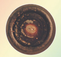
explains how to test and clean Multec II injectors (fig.
8).
In time, fuel injector(s) may become restricted, due to buildup in the
injector passages. Restrictions cause an injector to run lean. Driveability
symptoms include difficult starts, rough operation and possible misfire.
The MIL may illuminate.
Injector cleaning has three phases: dealing with fretting corrosion,
injector balance testing, and cleaning.
You will find these procedures detailed in the bulletin. Here, we want
to provide you some of the reasons behind the procedures.
Fretting Corrosion
Fretting is a microscopic rubbing motion between the terminal pin on
the injector and the terminal in the wiring harness (see June 2003 TechLink
for an extensive discription and illustrations).
Oxidized debris (corrosion), the result of fretting, can build up in
the injector terminals, resulting in high resistance or loss of continuity.
A fretted connection is unstable, and may vary between good, high resistance
and open.
TIP: The reason
to be concerned about fretting is that it can cause symptoms that mimic
a restricted injector.
To ensure that fretting is not an issue, follow the bulletin procedure
to apply dielectric grease to both cavities of each injector connector.
| Dielectric
Grease -- US |
Dielectric
Grease -- Canada |
| 12377900 |
10953529 |
Injector
Balance Testing
TIP: An important
reason for balance testing is that it quickly and graphically indicates
the flow of each injector, and permits comparing the performance of each
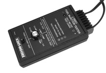
injector with the others. J-39021 Fuel Injector Tester is shown in fig.
9. Refer to the December 2002 TechLink for a detailed description
of injector balance testing.
TIP: You must record
the results of all injector balance tests and keep them with the repair
order. For your convenience, the bulletin has a worksheet for recording
the test results.
The test procedure calls for attaching a pressure gauge to the fuel rail.
The gauge must be in good operating condition and capable of reading in
kilopascals (kPa). The gauge in the J-34730 PFI Diagnostic Kit is recommended.
TIP: The reason
for reading kPa instead of psi is that kPa is a much smaller measuring
increment, which permits a much more precise measurement.
After determining the amount of pressure drop for each injector, compare
the results. If the difference between the highest (richest) and lowest
(leanest) injector is less than 20 kPa, the injectors are all flowing
within an acceptable range. If the difference is 20 kPa or more, proceed
with cleaning.
TIP: An injector
that is considerably richer than the rest must be replaced. An injector
that is leaner than the rest may be restricted, and may benefit from cleaning.
Research indicates that an injector running lean could lead to a driveabiltiy
condition.
Injector Cleaning
TIP: GM Top-Engine
Cleaner is the only approved injector cleaner. Research shows that GM
Top-Engine Cleaner is the most effective cleaner and won’t cause
damage to plastic or metal components in the fuel injection system when
used as instructed.
| GM
Top Engine Cleaner -- US |
GM Top Engine
Cleaner -- Canada |
| 12346535 |
992872 |
| Pre-measured
0.812 oz. (24 ml) bottles |
15 oz. (443.6
ml) bottle |
TIP:
Per
the bulletin, the injector cleaning process is run twice, to ensure thorough
cleaning of the injectors.
For each batch of cleaning agent, add two 24 ml bottles (US) or measure
1.6 oz. (48 ml) (Canada) into the J-35800-A injector cleaning tool (fig.
10) and top off with unleaded gasoline. This will result in a 10%
mixture.
TIP: The recommended mixture of GM Top-Engine Cleaner
has been increased from 5% to 10%. The reason is to improve effectiveness
of the injector cleaning procedure. Research shows that concentrations
greater than 10% do not improve effectiveness.
Follow the procedure when hooking up the injector cleaner equipment.
TIP: It’s
important to use the appropriate tools to block the fuel feed and return
lines. The reason is to isolate the cleaning agent to the fuel rail only,
and to prevent getting it into the fuel tank, which could damage the fuel
pump check ball.
-
Thanks to Dave Peacy |
figure
8
|
| |
| |
figure
9 |
| |
| |
| |

figure
10 |
|
return
to Table of Contents |
|
| Pass-Through
Capability Added to Vehicle Data Recorder |
The
2004 mid-year Vehicle Data Recorder (VDR) software (J-42598-100) will
be available in late July or early August, and will add model year 2004
chassis coverage for GM vehicles. Also included in the software update
is full powertrain/chassis support for GM Medium Duty Trucks. This software
will support both the original VDR (J-42598) and the new CAN+ VDR (J-42598-B).
An additional feature of the 2004 mid-year VDR software is a live PC
data screen. This allows the user to view live data stream information
on a standard desktop PC or laptop with Windows 98 SE, 2000 Professional,
or XP Professional. The same screen that currently displays the snapshot
data will also display the live data stream information. DTCs can also
be displayed while viewing live data stream.
Procedure for viewing live data:
- Using the new mid-year software update on a PC, download vehicle template
in the same manner as taking a snapshot recording (press select vehicle
button, choose model year, vehicle make, vehicle model and data list).
- Place a PC with the 2004 mid-year VDR software loaded in the vicinity
of the vehicle.
- Connect one end of the Tech 2 RS232 cable (3000110) and 9 PIN COM
port adapter (3000111) to the base of the VDR, and connect the other
end of the RS232 cable to the PC.
- Connect the VDR OBDII cable to the OBDII connector in the vehicle.
- Start the vehicle and press the Live Data button in the 2004 mid-year
VDR software.
- Live data stream now appears on the PC screen.
- The DTC button in the 2004 mid-year VDR software can now be pressed
to view DTCs.
TIP: The new
live data stream feature can be used only on the new CAN+ VDR (J-42598-B).
The original VDR (J-42598) is NOT capable of displaying the live data
stream.
TIP: The VDR
is useful in solving intermittent driveability problems, but also has
additional uses such as viewing live data (explained above), and capturing
information during the crank mode. The CAN+ VDR can be set up to capture
data while cranking. This could be helpful in a crank no start or cold/hot
start complaints.
-
Thanks to Mike Banar |
|
return
to Table of Contents |
|
| New
TXV Valve for A/C |
GM
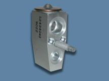
HVAC Engineering has developed an updated Thermal Expansion Valve (TXV)
for the 2005 Cadillac XLR (fig. 11). This
new Low Maximum Operating Pressure (Low MOP) TXV helps to better control
the high-side refrigerant pressure in high ambient temperatures, to
optimize A/C system performance. This new TXV can also be used as a
retrofit for the 2004 Cadillac XLR if customers are commenting on:
- Intermittent operation
- A/C blowing hot, moist air on occasion
- The engine cooling fan remaining on, frequently after the engine is
shut off
- The engine cooling fan frequently running at maximum speed
The Low MOP TXV contains a smaller amount of fluid charge in the TXV
bulb, which is located on the top side of this TXV. As the system refrigerant
temperature rises, the bulb charge begins to change from a liquid to
a gas. Because of its smaller amount of charge, it fully changes to
a gas more quickly than the stock TXV. Once the bulb charge is entirely
gaseous, the TXV acts as a pressure regulator, which is less influenced
by refrigerant temperature.
This pressure regulator helps to control overall system pressure sooner.
This results in less fan speed needed for condensing and continuous
operation of the A/C system in hotter climates by preventing compressor
disengagements due to high A/C head pressure. The Low MOP TXV is a better
match for the pressure range of this A/C system.
Always follow the A/C Performance Diagnostic in SI to verify the system
is performing to specifications before replacing any parts.
- Thanks to Chris Semanisin |
figure
11 |
| return
to Table of Contents |
|
| Transmission
Fluid Level |
The
Strasbourg 5L40E and 5L50E automatic transmissions (used in Cadillac
CTS, XLR, and SRX) have a non-traditional method of checking fluid level.
It is not done at normal operating temperature, but in a narrow range
between 86°F to 122°F (30°C to 50°C).
- Thanks to Bob Martin |
| |
| return
to Table of Contents |
|
| Battery
Disconnect/Connect |
Proper
battery disconnect/connect procedures and precautions are presented
numerous places in SI. It’s important to observe and perform the
instructions as presented. Failure to do so can cause personal injury,
cause damage to the vehicle and its components, and cause various DTCs
to set.
The following information highlights the proper steps to take when disconnecting
or connecting a battery. For specifics, always consult the SI section
that applies to the vehicle you’re servicing.
IMPORTANT: To reduce the
risk of personal injury while working near a battery, observe all safety
precautions presented in SI.
Disconnecting Procedure
1. Record all preset and theft codes from the radio.
2. Turn off all lamps and accessories.
3. Turn the ignition switch to the OFF position.
4. Loosen the battery negative cable nut.
5. Disconnect the battery negative cable from the battery.
Connecting Procedure
1. Connecting the battery cable(s) should be done only with the ignition
switch in the OFF position. Connecting the battery when the ignition
switch is in the ACCESSORY or RUN positions can cause various DTCs to
set.
TIP: If you do
the connection incorrectly, clear DTCs before investigating any trouble
codes for component failure.
2. Clean any existing corrosion from the battery terminal and battery
cable using a wire brush.
3. Connect the battery negative cable to the battery. Tighten the battery
cable nut to specification.
4. Reset all preset and theft codes previously recorded to the radio.
-
Thanks to Marty Case |
| return
to Table of Contents |
|
| Cracked
Serpentine Belt |
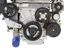
All
current GM vehicles designed and manufactured in North America were assembled
with serpentine belts made with an EPDM material and should last the life
of the vehicle (fig. 12). It is extremely
rare to observe any cracks in EPDM belts and it is not expected they will
require maintenance before 10 years or 150,000 miles (240,000 km) of use.
Older style belts, which were manufactured with a chloroprene compound,
may exhibit cracks depending on age. However, the onset of cracking typically
signals that the belt is only about half-way through its usable life.
A good rule of thumb for chloroprene-based belts is that if cracks are
observed 1/8-inch (3 mm) apart, all around the belt, the belt may be reaching
the end of its serviceable life and should be considered a candidate for
changing. Small cracks spaced at greater intervals should not be considered
as indicative that the belt needs changing.
TIP: Any belt that
exhibits chunking should be replaced.
- Thanks to Jay Dankovich |
figure
12 |
|
return
to Table of Contents |
|
| Scrolling
Radio Display |
Customers
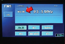
with 2004-05 vehicles that have a Delphi navigation radio may comment
that the preset display (fig. 13) sometimes
contains either a scrolling message or an unexpected message instead
of the station ID. Some customers may find this confusing and distracting.
The fault is not with the radio. The radio station is broadcasting improper
messages in place of the authorized station ID letters.
-
Thanks to Kelly Lynch |
| 
figure
13
|
| return
to Table of Contents |
|
| Oil Life
System Reset Procedures -- Trucks |
Many
GM cars and trucks are equipped with an oil life system that determines
when an oil change is required. After the oil has been changed, it’s
necessary to reset the system.
Procedures for resetting 2001 through 2005 trucks are published here.
Passenger cars will be published next month.
The information for this article is the same as you will find in the
applicable owner or service manual.
To find this information in 2001-4 eSI service manuals:
- Select the vehicle
- Select category General Information
- Select category Maintenance and Lubrication
- Select category Maintenance and then GM Oil Life System-Resetting.
Beginning with 2005, this information will be found only in owner manuals.
To find this information in eSI owner manuals:
- Select the vehicle
- Select Owner Manual
- Select Service and Appearance Care
- Select Checking Under the Hood
- Select Description and Operation
- Select Engine Oil Life System
TIP: You may
be able to use the Search function using the words Oil Life System Resetting.
TIP: You can
find copies of charts for earlier models on the TechLink website on
the Internet at http://service.gm.com. Look for the February and March
2000 issues and May and June 2003 issues.
2001 - 05 Aztek
2002 - 05 Rendezvous
If the vehicle does not have the optional Driver Information Center
(DIC) do the following:
1. With the ignition key in ON but the engine off, fully push and release
the accelerator pedal slowly 3 times within 5 seconds.
2. Turn the key to OFF.
3. If the CHANGE ENGINE OIL message comes back on, the engine oil life
monitor has not reset. Repeat the procedure.
If the vehicle has the optional DIC, do the following:
1. Turn the ignition to ON with the engine off.
2. Press the MODE button until the DIC reads OIL LIFE LEFT/HOLD SET
TO RESET.
3. Press and hold the SET button until 100% is displayed.
You will hear three chimes and the CHANGE ENGINE OIL message will go
off. If the CHANGE ENGINE OIL message comes back on, the monitor has
not reset.
Repeat the procedure.
2001 - 05 Montana
2001 - 04 Silhouette
2001 - 05 Venture
2005 Terazza
2005 Uplander
2005 Montana SV6
2005 Relay
1. With the ignition key in RUN but the engine off, repeatedly push
the trip/reset button until OIL is displayed on the Driver Information
Center.
2. Once OIL is displayed, push and hold the trip/reset button for five
seconds. The number will disappear and be replaced by 100 (indicating
100% oil life remaining).
3. Turn the key to OFF.
4. If the change engine oil message comes back on, the engine oil life
monitor has not reset. Repeat the procedure.
2002 - 04 Bravada
2002 - 05 TrailBlazer
2002 - 04 Envoy
2004 - 05 Ranier
Without DIC
1. Turn the ignition key to RUN with the engine off.
2. Fully press and release the accelerator pedal 3 times within 5 seconds.
3. If the CHANGE ENG OIL light flashes for five seconds, the system
is reset. If the light does not flash, repeat the procedure.
With DIC
1. Press the fuel information button until ENGINE OIL LIFE appears in
the display.
2. To reset the monitor, press and hold the select button while ENGINE
OIL LIFE is displayed.
2004- 05 Canyon
2004- 05 Colorado
1. Turn the ignition to RUN but with the engine off.
2. Press and release the reset button in the DIC until the Oil Life
message is displayed.
3. Once the alternating OlL Life and Reset messages appear on the DIC
display, press and hold the reset stem until several beeps sound. This
conforms the oil life system has been reset.
4. Turn the key to Lock.
If the CHANGE/OIL message comes back on when you start the engine, the
engine oil life system has not reset. Repeat the procedure.
2003- 05 SSR
1. Press the fuel information button until ENGINE OIL LIFE appears in
the display.
2. To reset the Oil Life System, press and hold the select button while
ENGINE OIL LIFE is displayed.
3. If the light comes back on again when you start the engine, you will
need to reset the system again.
2005 Equinox
2001 - 05 Sierra (Exc. some fleets)
2002 - 05 Sierra Denali
2001 - 05 Silverado (Exc. some fleets)
2001 - 05 Yukon and Yukon XL
2001 - 05 Tahoe and Suburban
2001 - 05 Escalade
2002 - 05 Escalade EXT
2002 - 05 Avalanche
2001 - 05 Yukon Denali
2003 - 05 Hummer H2
2003 - 05 Express (Exc. some fleets)
2003 - 05 Savana (Exc. some fleets)
1. Turn the ignition to RUN but with the engine off.
2. Fully push and release the accelerator pedal slowly 3 times within
5 seconds.
3. If the Change Oil Soon light flashes, the system is resetting.
4. Turn the key to Lock.
5. Start the engine.
6. If the Change Oil Soon light comes back on, the system has not reset.
Repeat the procedure.
2002- 05 Saturn Vue
1. Turn the ignition to RUN but with the engine off.
2. Fully push and release the accelerator pedal 3 times within 5 seconds.
3. If the Change Oil Soon light flashes, the system is resetting. The
light will flash for up to 30 seconds or until the ignition is turned
to OFF.
4. Turn the key to OFF.
5. Start the vehicle.
6. The oil life will change to 100%.
7. If the Change Oil Soon light comes back on or stays on for 30 seconds
at the next ignition cycle, the system has not reset. Repeat the procedure.
2001 - 05 B7 Chassis Medium Duty
1. Turn the ignition to START but with the engine off.
2. Fully press and release the accelerator pedal slowly 3 times within
10 seconds.
3. If the CHANGE OIL light flashes for five seconds, the system is reset.
4. If the light does not display for five seconds, you will need to
reset the system again.
2003 - 05 560 C-Series
All except with Caterpillar diesel:
1. Turn the ignition to RUN but with the engine off.
2. Fully press and release the accelerator pedal slowly 3 times within
10 seconds.
3. If the CHANGE OIL light flashes for five seconds, the system is reset.
4.Turn the key to OFF.
5. If the light comes back on again when you start the engine, you will
need to reset the system again.
All with Caterpillar diesel:
1. Turn the ignition to RUN but with the engine off.
2. Fully apply and hold the brake pedal while you fully press and release
the accelerator pedal 3 times within 5 seconds.
3. Turn the key to OFF.
4. If the light comes back on again when you start the engine, you will
need to reset the system again.
-
Thanks to Jerry Garfield |
| return
to Table of Contents |
|
| Engine
Oil Capacity Table on Website |
An
engine oil capacity table for all 2005 cars and trucks has been placed
on the TechLink website.
Go to http://service.gm.com and
click on TechLink. After selecting your language choice, click on the
Reference Guides button. Locate and click on Oil Capacities for 1988-2005.
-
Thanks to Jerry Garfield |
|
|
| return
to Table of Contents |
|
| Drive
Sprocket Support |
On
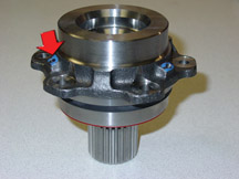
some 4T80E transmissions, used in 2003 DeVille, Seville and Aurora,
the drive sprocket support oil holes may not be completely drilled.
The converter seal may be dislodged and/or the spring may be mispositioned.
Symptoms include oil leaks in the converter area.
Replacing the converter seal alone may not correct the condition. Inspect
the drive sprocket support for completely drilled oil holes. Blow compressed
air through holes (fig. 14) and listen
for airflow out of the converter spline side. If the holes are not drilled,
replace the drive sprocket support.
TIP: Corrective
action has occurred in the transmission assembly plant. Date codes are
not available to allow identification of suspect transmissions.
-
Thanks to Darryl Butler |
figure
14
|
| return
to Table of Contents |
|
| GTO
Steering Wheel |
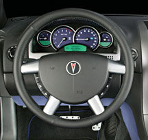
When
servicing the 2004 GTO steering wheel (fig. 15),
note that the spoke covers are available in packages of four (p/n 92147964).
Do not replace the steering wheel if only the covers need replacement.
-
Thanks to Art Spong |
figure
15 |
| return
to Table of Contents |
|
| Door
Trim Panel Reflector |
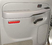
An
upcoming bulletin announces that individual rear door trim panel reflectors
15183155-56 are now available for the 2003-04 C/K truck.
TIP: If the reflector
needs to be replaced, DO NOT replace the entire door panel (fig.
16).
TIP: To remove
the reflector, insert a flat-bladed tool behind the reflector and carefully
pry it out, to avoid damaging the panel.
-
Thanks to Jim Kukula |
figure
16 |
| return
to Table of Contents |
|
| Rear
Shock Absorber Upper Rubber Mount |
Bulletin
04-03-09-001 refers to 2000-04 Cadillac DeVille.
The upper rubber mount 22182918 is now a serviceable component for the
the rear shock absorber assembly.
-
Thanks to Bill Denton
| Rear
Shock Absorber Assembly |
Description |
Part
Number |
| 22064808 |
Upper
Rubber Mount -- Rear Shock Absorber |
22182918 |
| 22064809 |
| 22064872 |
| 22064873 |
| 88955460 |
| 88955461 |
|
| return
to Table of Contents |
|
| Oil
Pump to Case Seal |
This
information applies to 2004 Light Duty Trucks, Corvette and GTO.
General Motors Powertrain has made a design change to oil pump to case
oil seal on the 2004 4L60E (M30) and the 4L65E (M32). The new seal is
a stamped molded seal and replaces the O-ring style seal previously
used. The two seals are not interchangeable.
The new seal is being phased into production starting in March of 2004.
When servicing transmissions with the new design stamped molded seal,
use following precautions:
- The outer diameter of the pump assembly and case bore must be clean
and free of burrs or raised surfaces. Be aware of sharp edges that could
damage the seal during installation.
- The seal should be clean and dry before installation. It does not
require lubrication for installation.
- Before installation, inspect the seal for obvious damage.
- It is preferable to hand-start the seal, positioning the seal evenly
around the case bore, before installing the torque converter housing.
- The seal can be easily removed by prying it out, typical of a pressed-on
seal.
- The seal may be reused. However, throughly inspect the seal for:
-- Distortion of metal carrier or separation from the rubber seal
-- Cut, deformed, or damaged seal.
- The new stamped molded oil pump to case seal will not service transmissions
produced before the design change, nor will the previous O-ring style
seal work in place of the stamped molded seal.
- The new stamped molded seal requires that the oil pump be installed
and torqued before installing the molded seal. The molded seal is seated
into position by installing and torquing the torque converter housing.
An informational TSB is in process and SI is being updated to include
the new service procedures for the new stamped molded oil pump to case
seal.
-
Thanks to Mark Gordon |
| |
| return
to Table of Contents |
|
| Transmission
Clunk Bump Noise |
The
2004 All Wheel Drive (AWD) Cadillac SRX may exhibit a clunk bump noise
when completing range shifts of Drive to Reverse and Reverse to Drive.
The condition may be intensified by abruptly accelerating before the
transmission is fully engaged into range. The clunk bump condition is
a result of internal lash build-up within the transfer case and driveline.
This condition is considered to be a characteristic of the AWD system.
The vehicle should be compared to a like vehicle with similar mileage.
Attempts to repair this condition have proven unsuccessful.
-
Thanks to Mark Gordon |
| |
| return
to Table of Contents |
|
 Car Issues – Fix It Right The First Time
 |
Model
Year(s) |
Vehicle
Line(s) --
Condition |
Do
This |
Don’t
Do This |
Reference
Information / Bulletin |
2001-2004 |
Aztek,
Rendezvous (FWD), Venture/Montana/Silhouette – Pop and/or
Rattle in Exhaust Down Pipe |
Follow
procedure in bulletin using clamp on down pipe to correct rattle/buzz
noise. |
Don’t
replace converter assembly for rattle/buzz noise without completing
instructions in bulletin. |
03-06-05-003 |
2000-2004 |
All
Cars with 4T40/4T45E and 4T65E – Light On/Various Transmission
Codes Stores |
Check
transmission 20-way connector for secure connection |
Don’t
replace transmission, TCC PWM, VSS, PCS or valve body. |
02-07-30-022B |
1998-2004 |
Seville
– Heated Seat Inoperative |
Replace
only needed heating element. |
Don’t
replace entire seat cover if heated seat element is inoperative. |
01-08-50-002C |
2001-2004 |
Century/Regal
– Intermittent SES, ABS or TCS Lamp Illuminated, Engine
No Crank/No Start, Various I/P Cluster Intermittents, DTCs Set,
Shifter Locked in Park (BTSI Inoperative) |
Check
UBEC harness connectors for damage and replace damaged terminals. |
Don’t
replace UBEC, ignition switch, SDM, BCM, shifter assembly (Regal)
or intermittently inoperative clusters. |
03-08-45-004 |
2000-2004 |
Cavalier/Sunfire/Alero/Grand
Am – Inoperative Sunroof Module |
Retime
module or replace only motor for inoperative complaints. |
Don’t
replace entire sunroof module assembly. |
03-08-67-009A |
2003-2004 |
Cavalier/Sunfire
– Air Conditioning Compressor Noisy |
Inspect
for ground out conditions that can cause A/C compressor noise
complaints. |
Don’t
replace A/C compressor for excessive noise without inspecting
for ground outs. |
03-01-38-012 |
1999-2004 |
All
Cars and Trucks – Brake Warranty, Service and Procedures |
Issue
One: Refinish brake rotor.
Issue Two: Measure for LRO |
Issue
One: Don’t replace the brake rotors.
Issue Two: Don’t measure for LRO |
00-05-22-002D |
2003-2004 |
CTS
– Variable Effort Steering (VES) “Service Steering
Message,” DTC C1241 or C0450 |
Replace
only VES solenoid. |
Don’t
replace entire steering gear. |
03-02-36-001 |
2003 |
All
cars with 4T40/45E, 4T65E and 4T80E – Code P0742 |
Replace
TCC PWM Solenoid |
Don’t
replace transmission, torque converter or valve body assembly. |
02-07-30-039C |
2000-2003 |
LeSabre,
Park Avenue, Regal, Impala, Monte Carlo, Bonneville, Grand Prix
With 3.8L V6 Engine (RPO L36) – Loss of Coolant, Milky Colored
Oil |
Replace
upper intake manifold gasket only. |
Don’t replace upper intake manifold assembly for coolant
leak condition. |
03-06-01-016 |
|
| return
to Table of Contents |
|
|
 Truck Issues – Fix It Right The First Time (new issues in bold)
|
Model
Year(s) |
Vehicle
Line(s) --
Condition |
Do
This |
Don’t
Do This |
Reference
Information / Bulletin |
2002-2004 |
Fullsize and Midsize Pickups and Utilities – Labor Operation
Assignments for Control Module Reprogramming |
When
reprogramming an electronic module, use labor operation that reflects
module being programmed. |
Do
not use K5364, which is for reprogramming TCM, when reprogramming
TCCM. |
02-04-21-006D |
2002-2004 |
Fullsize and Midsize Pickups and Utilities – Sleepy New
Venture Gear Transfer Case Control Module |
Verify
sleepy module as primary cause. Reprogram TCCM with latest software |
Don’t
replace encoder motor or transfer case. Replace the module only
if a C0550 DTC shows as current or in history. |
02-04-21-006D |
2004 |
Fullsize Pickups – 6.6L LLY Diesel Engine Injectors |
04
LLY Duramax fuel injector is on restriction. Contact TAC for authorization. |
Do
not replace an LLY Duramax injector prior to contacting TAC. |
GM
Messenger VSS20040067 |
2002-2003 |
Chevrolet
Avalanche and Cadillac Escalade EXT – Cargo Covers and Cladding
Faded or Stained |
Thoroughly
clean, dry and treat components with “Armor-dillo.”
To order call (888)393-4722 or online at www.armor-dillo.net. |
Don’t
replace cargo covers for this condition. |
04-08-111-001 |
2002-2004 |
Fullsize and Midsize Pickups and Utilities – Transfer Case
CNND Labor Operation |
Use
Labor Operation K9993 whenever transfer case issue on a 4WD or
AWD vehicle cannot be duplicated or resolved after diagnostic
efforts. |
Don’t
use Labor Operation K9992, which is for manual transmission concerns
or Labor Operation K9995, which is for automatic transmission
concerns. |
Service
VME
VSSM20030117 |
2002-2004 |
Fullsize
Pickups – Rear Leaf Spring Slap Noise |
Replace
inserts and rubber washers. |
Don’t
replace leaf spring. |
03-03-09-002 |
| 2002-2004 |
All
Passenger Cars and Trucks – Air Conditioner Compressor Diagnosis |
Follow
SI and bulletin for diagnostic information before compressor replacement. |
Don’t
replace air conditioning compressor. |
01-01-38-013A
03-01-38-019 |
| 2002-2004
|
All
TrailBlazers, All Envoys, Bravada, Rainier with HomeLink Universal
Transmitter – Programming Diagnosis |
Use
J 41540 – GM Integrated HomeLink Tester (essential tool).
Follow SI and refer customers to their Owner’s Manual. |
Don’t
replace HomeLink Transceiver without validating internal fault |
01-08-97-001B |
| 2002-2004 |
All
TrailBlazers, Envoy, Envoy XL, Bravada – Squeak/Rub/Scrub
Type Noise in Steering Column |
Lubricate
and remove material, per bulletin. |
Don’t
replace upper or lower intermediate shaft. |
02-02-35-006A |
2001-2004 |
Fullsize
Pickups and Utilities – Servicing Wide Load Mirrors (RPO
DPF) |
Replace
individual parts as needed. |
Don’t
replace complete mirror assembly. |
03-08-64-028
|
|
| return
to Table of Contents |
|
|
| Know-How
Broadcasts for August |
| |
 |
| Know-How
Broadcasts for August |
| 10280.08D
Emerging Issues
- Pontiac, Buick, GMC
- Chevrolet Cars and Trucks
- Cadillac and Hummer |
August
12, 2004 |
All
Eastern Time:
12:30 PM,
1:00
PM,
1:30 PM
|
| 10280.20D
Technology Close-Up/ New Model Features - TBD |
August
26, 2004 |
9:00
AM, 12:30 PM, 3:00 PM Eastern Time |
| -
Thanks to Tracy Timmerman |
|
|
| return
to Table of Contents |
|
|


 Car Issues – Fix It Right The First Time


 Truck Issues – Fix It Right The First Time (new issues in bold)