|
|
Note: Clicking
on any picture or illustration will open a larger version of that art.
|
|
Battery
Charger for Programming |
An
article in the April 2004 issue of TechLink explained the potential
consequences of using a battery charger during programming. Stable battery
voltage is critical during programming. Any fluctuation, spiking or
loss of voltage will interrupt programming, which could cause the controller
to lock up. Two critical items are:
- Precise voltage control
- Clean DC (AC eliminated)
Dealers, however, recognize that programming time has increased dramatically
and may now run upwards of 60 minutes for some applications. This is
due to larger calibration files and GMLAN controllers that take longer
to program.
The programming of modules requires the ignition key to be turned on,
without the engine running. This, of course, means that during the programming
event, the vehicle’s systems are operating from the vehicle battery.
So, battery charge is critical.
For these reasons, an external power source would be desirable.
Good news. GM recently validated the Midtronics PSC line of chargers
for use while programming controllers/modules (fig.
1). Two output levels are available -- the 30 amp PSC-300 and
the 55 amp PSC-550.
Features
The PSC charger is extremely easy to use. Simply attach the cables to
the battery, plug in the charger power cord, and you’re ready
to charge (fig. 2).
- No dials or controls to set
- Clean, noise-free DC voltage to support programming activities (<
50 mV rms)
- Fully regulated output prevents overcharging
- Over-current protection -- cycle-by-cycle peak limiting, as well as
rated current limiting to maximize the life of the converter
- Output voltage approximately 13.4 vdc at full load
- Reverse polarity protection
- Works with 12v flooded lead batteries as well as AGM (absorbed glass
mat) batteries
- Switch-mode design reduces heat build-up
- Proportional fan control regulates fan speed according to converter’s
temperature, minimizing fan noise
- When used during programming, the PSC supports loads, and charges
the vehicle’s battery (battery will be returned to customer in
higher state of charge than when it entered the service bay).
- When battery is charged, the charger acts as a regulated power supply
to sustain accessory loads and offset parasitic drain.
- Quiet, small and compact for portability
- Detachable cables for easy field service
Carrying Case
The carrying case permits you to use the PSC charger without fear of
damage to paint, trim or interior components. The case is designed to
allow the charger to be operated while inside the case
(fig.3). With the case cover closed, only the cables are exposed.
Other Uses
The PSC charger will deliver current up to the rated value, to charge
a 12-volt automotive battery when battery voltage is depressed due to
discharge.
Because the PSC charger is compact and quiet, it is suitable for continuous
use in the showroom. It will maintain the battery in your showroom display
vehicle, permitting the salesperson to demonstrate power-consuming accessories
and electronic devices without the embarrassment of power loss.
How to Obtain
These chargers are available from GM Dealer Equipment (1.800.GM.TOOLS).
You can order either the 165-PSC-300K (30 amp) or the 165-PSC-550K (55
amp).
-
Thanks to Steve Marek, Midtronics |
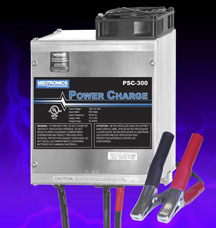
figure 1 |
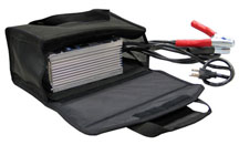
figure 2 |
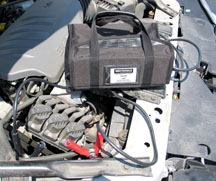
figure 3 |
| |
| |
| |
| return
to Table of Contents |
|
|
| TIS
2 Web, Phase 2 |
Last summer, GM Service and Parts Operations launched TIS 2 Web, a new
version of the TIS diagnostic/programming application that operates
from a central Internet site. The first phase of this new application
enabled dealers to update their Tech 2 software. Today, nearly 90% of
all U.S. and Canadian dealers are downloading Tech 2 updates using TIS
2 Web.
By making the software updates available from a central site instead
of locally at the dealership, TIS 2 Web provides increased updates,
consistent software version utilization and improved support for all
users.
Service Programming System
The next phase of TIS 2 Web includes the release of Service Programming
Systems (SPS). Accessing SPS from TIS 2 Web will allow dealers to download
calibrations from the website.
With this upgrade, technicians will no longer have to wait for data
broadcasts to GM ACCESS for calibrations, and at the same time it will
allow GM engineering to significantly increase the speed at which calibrations
are released. In addition, SPS will reduce the number of VCI requests
and instances of missing VINs.
The transition to the new version of SPS will be easy for technicians.
With the exception of some minor enhancements to SPS functionality,
TIS 2 Web SPS operates very much as SPS currently does in the dealership.
Phase 2 Timing
Phase 2 of TIS 2 Web, featuring the release of SPS, will begin as a
pilot program in July at approximately 200 participating dealers throughout
the five regions in the U.S. and Canada.
All U.S. and Canadian dealers are expected to have access by the fall
of 2005.
Phases 3 and 4 will be the final phases of TIS 2 Web, and will include
Tech 2 View and Snapshot Upload/Display. Look for these releases in
early 2006.
TIS 2 Web Access Requirements
A dealer admin message will announce the production release of TIS 2
Web SPS. To access TIS 2 Web SPS, launch TIS from the Techline PC and
click on the SPS Web icon on the TIS main screen. It operates much like
the Tech 2 Software Download.
TIS 2 Web also can be accessed by clicking either the Parts or Service
tabs in DealerWorld (U.S.) or GM infoNET (Canada).
To operate TIS 2 Web effectively, Dealers must have:
- The appropriate Techline PC hardware requirements as part of the Multiple
PC Initiative (MPI). (See http://service.gm.com/techlineinfo/techlinepc.html
for hardware requirement details or contact your Techline Consultant
for more information.)
- High-speed Internet connectivity at the Techline PC.
- Individual DealerWorld (autopartners) ID and password for each technician.
TIP: DealerWorld IDs are managed by the dealership’s
Partner Security Coordinator. Security parameters in place will not
allow ID/PW credentials to be shared.
Techline Support
If you need assistance with TIS 2 Web SPS as it is released or with
TIS 2 Web Software Download, contact the Techline Customer Support Center
(TCSC) at 1.888.337.1010, prompt 3. Saturn retailers may use 1.888.7SATURN
for assistance. In Canada, 1.800.828.6860 English, 1.800.503.3222 French.
- Thanks to Mike Waszczenko |
|
|
| |
|
|
TechLink Subscription |
Reminder
U.S. dealers have the ability to manage some of the content in their
weekly Dealer World Delivery (DWD) Box. Using the Dealer Subscription
application (fig. 4), located on the DWD
Store website, dealers have the ability to select which periodic publications
they want mailed to their dealership. TechLink is included in this procedure.
Dealers have the ability to select which publications they would like
to receive, as well as the quantity. Dealers will have the ability to
continuously adjust their DWD box.
IMPORTANT: If
a dealer fails to enroll in the subscription process or does not select
a specific publication, the default 'ship to' amount is zero (0). In
other words, if no selection is made, the dealer will not receive the
publication.
-
Thanks to Mark Stesney |
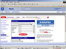
figure 4 |
| return
to Table of Contents |
|
| Door
Lock Switches |
This information applies to the 2005 Chevrolet Equinox.
The door lock switch is retained in the bracket by two tabs. The tab
closest to the electrical connector is less flexible than the other
(fig. 5).
If disassembly and assembly are done incorrectly, you may break the
lock tab on the side of the switch closest to the connector.
Disassembly
Apply pressure with finger or screwdriver on the locking tab that is
furthest from the electrical connector.
Don't apply pressure with finger or screwdriver to the locking tab that
is closest to the connector.
Disconnect the electrical connector after removing the switch.
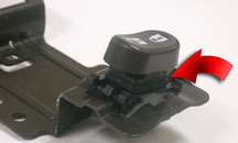
Assembly
Connect the electical connector before installing the switch.
Insert the locking tab on the switch that is closest to the electrical
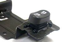
connector into bracket hole (fig. 6). Then,
place both thumbs on the switch and snap the remaining locking tab into
the bracket (fig. 7).
Don't push both locking tabs at once.
-
Thanks to Angelo Girolamo and David Cho |
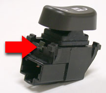
figure 5 |
figure
6 |
figure
7 |
| return
to Table of Contents |
|
| Accelerator
Pedal Position Sensor |
This information applies
to the 2004-06 Chevrolet Malibu and 2005-06 Pontiac G6.
The SES light may be on and/or various electrical concerns and multiple
or repeat Accelerator Pedal Position Sensor (APP) codes: DTC P2125,
P2120, and P2138.
If a vehicle is found to have multiple accelerator pedal codes or repeating
codes for the ETC pedal system, check the in-line connector C206 on
the left side of the instrument panel for water intrusion. Water in
this connector may cause SES, SVS, and APP codes, or other various codes
to set. The predominant codes set are for the Accelerator Pedal Position
Sensors. The diagnostic parameters for the pedal sensors are more sensitive
to this condition and may be the first to show the concern.
If you find water in connector C206 (fig. 8),
check for a possible water leak from the top of the A-pillar at the
ditch molding or sunroof drain and reseal/repair as necessary.
A. Radio Antenna Connector
B. C206
C. C208
-
Thanks to Dave MacGillis |
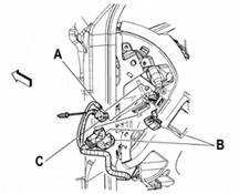
figure 8 |
| return
to Table of Contents |
|
| TOP
TIER Detergent Gasoline Marks One Year |
TOP
TIER standards developed by BMW, General Motors, Honda and Toyota were
aimed at reversing the national trend toward lower gasoline additive
concentration. The U.S. EPA requires a minimal amount of detergent additive
in all gasoline. However, the level is often not sufficient to prevent
engine deposits from forming. TOP TIER Detergent Gasoline helps keep
engines cleaner than gasoline containing the minimum amount required
by government regulation, and helps provide optimal fuel economy, performance,
and reduced emissions.
In the past twelve months, six fuel marketers have joined the TOP TIER
Detergent Gasoline program:
- ChevronTexaco
- QuikTrip
- ConocoPhillips
- Shell
- Entec Stations
- MFA Oil Company.
Together they represent about 35 percent of all the gasoline sold in
the U.S.
TIP: TOP TIER
gasoline suppliers are listed on the GM TechLink website, under the
Reference Guides tab. |
| |
|
return
to Table of Contents |
|
| Crossmember
Bolts |
On the 2004 and early 2005 (before April 2005) Colorado and Canyon,
the front crossmember-to-frame bolts were installed front-to-rear (fig.
9). This made crossmember removal more time consuming because
it was necessary to rotate the steering gear out of the way.
After April 2005, the assembly plant is installing the crossmember-to-frame
bolts rear-to-front (fig. 10).
The SI procedure now recommends that when the front crossmember-to-frame
bolts are reinstalled, they should be installed rear-to-front, so that
if future crossmember removal is needed, the steering gear will not
have to be rotated.
-
Thanks to Dan Stress |
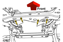
figure
9 |
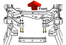
figure 10 |
| return
to Table of Contents |
|
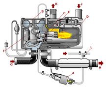
| Diesel
Coolant Heater |
A
supplemental coolant heater (Eberspächer model D5WZ) is available
on the 2006 diesel-equipped Chevrolet Express and GMC Savana Diesel
(2WD and 4WD) (fig. 11).
TIP: The parts
catalog, labor time guide and SI will refer to this as a Heater Coolant
Heater.
OPERATION
For ambient temperatures below 40°F (4°C), the coolant heater
provides supplemental heating energy for the passenger compartment.
It has a heat output up to 17,000 BTU (5kW).
The heater, located beneath the vehicle (fig.
12), operates on the vehicle’s 12 volt power supply and
diesel fuel. The system contains combustion chamber, fan, and fuel pump.
The heater has two heat levels and cycles between these levels to maintain
a consistent coolant temperature between 185°F and 194°F (85°C
and 90°C) called for by the control unit.
When the PCM requests supplemental heater operation, a signal from the
internal control unit starts the heater. A blower draws combustion air
into the heater's ignition chamber while fuel from the vehicle fuel
tank is drawn into the chamber by the heater's fuel pump and mixed with
the air. A glow plug ignites the fuel/air mixture, establishing a controlled
flame inside the sealed heat exchanger.
The D5WZ system has a flame sensor to abort the startup attempt if the
flame is not established, or to switch off the fuel pump in case the
flame is extinguished during operation. In both cases, an automatic
restart is performed.
The vehicle coolant pump continuously circulates coolant over the heat
exchanger and throughout the coolant system.
The coolant temperature regulation controls the heat mode from high,
low, and off. The coolant temperature sensors cycle the unit off if
the coolant temperature reaches the maximum set point.
- The Fuel Metering Pump (A) pumps the fuel out of the vehicle’s
fuel tank and into the combustion chamber (fig.
13).
- The Heater Blower (B) blows the oxygen, which is necessary for the
combustion process, into the combustion chamber.
- A Ceramic Glow Plug (C) generates the evaporation energy and creates
the temperature which is necessary to ignite the air-fuel mixture.
- The Heat-Exchanger (D) transfers the energy of the combustion process
into the engine coolant with an average efficiency of 81%.
- Depending on the coolant temperature, which is detected by the Temperature
Sensor (E), the heater operates at either high or low setting or is
shut off.
- The integrated Control Unit (F) with diagnostic interface and a redundant
overheating “watch-dog” provides highest functionality and
security.
A |
Fuel
Metering Pump |
B |
Heater
Blower |
C |
Ceramic
Glow Plug |
D |
Heat
Exchanger |
E |
Temperature
Sensor |
F |
Control
Unit |
G |
Air
In |
H |
Exhaust
Out |
J |
Coolant
In |
K |
Coolant
Out |
L |
Diesel
Fuel Line |
REGULATION
FUNCTIONS
Ambient Temperature Control -- For temperatures below
40°F (4°C), the diesel fuel operated heater provides supplemental
heating energy for the passenger compartment. An inferred ambient temperature
signal and engine run signal are provided by the PCM.
Coolant Temperature Control -- The diesel fuel operated heater
starts in high power and switches to low power when the coolant temperature
reaches 185°F (85°C). If the coolant temperature reaches 194°F
(90°C), the heater switches off and restarts once again at 167°F
(75°C). It switches back to high if the coolant reaches 167°F
(75°C) in low power mode.
SERVICE DIAGNOSTIC TIPS
An understanding of the unit’s operation and control logic may
be helpful in diagnosing improper operation. Here are some highlights.
Before every start of the heater, a self-test checks
the operation of the following components:
- Control unit
- Flame sensor
- Control sensor
- Overheat sensor
- Glow plug
- Fuel pump
- Blower motor
If the self test is passed, startup commences.
- Glow plug is turned on and heats combustion chamber
- Blower switches on
- Fuel pump supplies fuel to combustion chamber
- Fuel ignites
- Flame sensor senses that combustion has started, and glow plug is
turned off
If the first start is not successful, restart begins.
In this case, the glow plug voltage is increased to obtain greater heat
for starting. Then the first start sequence repeats.
If the second start is unsuccessful:
- Fault code is set
- Restart will occur only if ignition is switched off and back on.
- After 4 attempts, restart will not occur until fault memory is cleared.
When coolant reaches the specified temperature, shut off
(run-on mode) occurs:
- Combustion chamber is cooled and prepared for next new start
- Glow plug and blower are activated to clear the combustion chamber
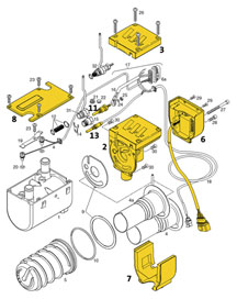
PARTS
A number of service parts are available for the supplemental Heater
Coolant Heater (fig. 14).
-
Thanks to Robert Tette
not
shown |
Coolant
Heater Assembly |
not
shown |
Air
Supply Hose |
not
shown |
Exhaust
Muffler |
13 |
Flame
Sensor |
8 |
Heat
Exchanger Cover |
6 |
Heater
Control Unit |
3 |
Upper
Cover |
2 |
Blower
|
7 |
Lower
Cover |
11 |
Glow
Plug |
|
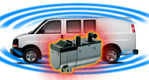
figure
11 |
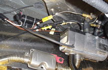
figure
12 |
| |
figure
13 |
| |
| |
| |
| |
| |
figure
14 |
| return
to Table of Contents |
|
| Camshaft
Position Actuators |
The
Vortec in-line engine family now consists of three engines:
Vortec 2800 LK5 (2.8L)
Vortec 3500 L52 (3.5L)
Vortec 4200 LL8 (4.2L)
All of these engines use an Exhaust Camshaft Position Actuator (cam
phaser) that allows the PCM to change the relationship of the camshaft
relative to the crankshaft, permitting better control over emissions
and performance (TechLink, November 2001). The style of cam phaser currently
used for the Vortec in-line engine family is a Splined Phaser and will
soon be changing to a Vane Phaser.
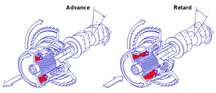
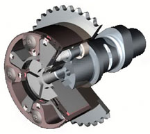
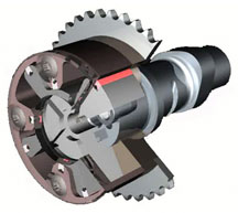
Review of Splined Phaser Operation
The splined phaser (fig 15) uses an internal
piston that connects the camshaft and cam phaser sprocket together using
helical splines, forming an adjustable mechanical link. A PCM commanded
control valve manages the oil pressure to the cam phaser internal piston.
The internal piston rides along the helical splines, rotating the cam
phaser gear and the camshaft opposite of each other, changing cam timing.
A spring within the cam phaser holds the piston in an advanced position
(0°) when no oil pressure is applied. This allows the engine to
start and run with the cam in the home position. When cam phasing is
desired, the PCM can retard the cam position up to 25° by varying
oil pressure to the piston through the control valve (fig.
16).
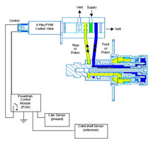
Vane Phaser Operation
The Vane Phaser is controlled the same way as a splined phaser, through
a control valve, but internally its components are very different. Instead
of using an internal piston with splines, a rotor with four vanes is
connected to the end of the camshaft. The rotor is housed inside of
the stator that is bolted to the cam gear.
The rotor and stator are not linked mechanically together as in the
splined phaser. Instead, oil pressure is controlled on both sides of
the vanes of the rotor, creating a hydraulic link to the stator. By
varying the balance of oil pressure on either side of the vanes, the
position of the camshaft can be controlled. A return spring is also
incorporated under the reluctor of the phaser to help return it to a
0° (home) position (fig. 17).
During start-up, when little oil pressure is available, an internal
spring-loaded locking pin keeps the rotor and stator locked together
in the home position. When phasing is desired, oil pressure is applied
to the phaser, unlocking the pin. As with the splined phaser, a 25°
cam retard can be achieved (fig. 18).
Cam Phaser Checks
Due to these differences, the cam phaser checks in SI have been modified.
For the splined phaser, you can check the ability for
it to rotate against the internal spring and also check the range of
motion at the same time by using a wrench to turn the camshaft (refer
to SI document 779675). Of course you have to remove the valve cover
to do this. This helps determine if there are internal problems with
the splined phaser.
The vane phaser has a locking pin that prohibits the
free movement of the rotor and stator when no oil pressure is applied.
You must remove the phaser from the engine, clamp the cam sprocket in
a vise, and apply air pressure to the oil port to unlock the pin and
check range of motion (refer to SI document 1530725). Be careful when
doing this. Oil will leak out of the cam phaser components when air
pressure is applied (this is normal). You also may see small oil bubbles
coming out of the cam sprocket itself. This is also normal. The cam
sprocket is made from powdered metal and is porous in nature.
Vane Phaser Service
The vane phaser is serviced as an assembly and must be replaced if:
1. it does not unlock when air pressure is applied
2. it does not lock when air pressure is removed
3. it does not move within the range of motion specified in SI.
-
Thanks to Randy Pearl, Delphi |
figure
15 |
figure
16 |
figure
17 |
figure
18 |
| return
to Table of Contents |
|
| Brake
Repair Bulletin Revision |
Corporate Bulletin Number 00-05-22-002E (Section 05 — Brakes)
is being revised to introduce a new labor operation for brake burnishing
as well as including the 2006 model year vehicles.
Brake Burnishing
When a vehicle is parked for long periods of time in humid conditions,
the braking surface area under the pads corrodes at a different rate
compared with the rest of the braking surface area (a condition known
as “lot rot”). This kind of corrosion can cause pulsation
due to thickness variation.
Cleaning up of braking surfaces (burnishing) can be accomplished by
10 to 15 moderate stops from 56 to 64 km/h (35 to 40 mph) with cooling
time between stops. If multiple moderate braking stops do not correct
this condition, the bulletin instructs you to follow the Brake Rotor
Clean-Up procedure, using an approved brake lathe.
Labor Operation for Burnishing
Bulletin 00-05-22-002E introduces a new labor operation H9709, which
is intended to cover the burnishing procedure. If burnishing clears
up the condition, use this code.
TIP: Labor operation
H9709 - Brake Burnish is not a published labor operation and will not
be found in the Labor Time Guide. This labor operation should be used
to claim the necessary time for cleaning up the braking surfaces for
thickness variation pulsation due to lot rot corrosion.
IMPORTANT: If
the pulsation condition remains after burnishing, you must follow the
Brake Rotor Clean-Up procedure. In this case, do not use
the H9709 labor code. The time to perform the burnishing procedure is
included in the labor time for Brake Rotor Clean-Up.
- Thanks to Steve Love |
| |
|
return
to Table of Contents |
|
| Corvette
Z06 Training
(not applicable in Canada) |
Chevrolet has determined that the following service
classes are essential to properly service and repair the 2006 Chevrolet
Z06. To qualify to receive distribution, dealers must agree to purchase
the Z06 essential tools and have completed the following service courses:
10290.13D – 2006 Chevrolet Corvette Z06 Features
& Systems (Service Know How Seminar)
10441.17D – 2006 Chevrolet Corvette Z06 Diagnosis
and Repair (IDL Broadcast)
16440.12D – Engines New and Updates (IDL Broadcast)
The 2006 Z06 will be the first US production car to use an aluminum
frame, magnesium cradle and carbon fiber body components. These high-tech
features require specialized service and repair procedures.
Dealerships that do not have a body shop can provide GM training for
their selected sublet facility. The technicians that take and pass the
training are entered in to the GM Training data base and assigned to
that dealership.
With the aluminum frame and carbon fiber panels, there are four classes
that will be required for body shop repairs. Taken together, these courses
will enable body service Corvette Z06 certification:
WCA01 – Aluminum GMA (MIG) Welding
WCA02 – Automotive Aluminum GMA (MIG) Welding Qualification
Test Prep
WCA03 – Automotive Aluminum GMA (MIG) Welding Qualification
Test
GEN01 – 2006 Corvette Z06 Collision Repair Overview
TIP: The Aluminum
(MIG) Welding courses must be taken in sequential order.
I-CAR has been selected to develop and provide this training. You can
access the I-CAR training site through the GM Training web site at www.gmtraining.com
and click on the associated links to I-CAR. The I-CAR help desk phone
number is 1.800.422.7872, and the website is www.i-car.com.
TIP: You must
pre-register at least four weeks in advance with I-CAR. You must pre-pay
I-CAR; payment options are on the pre-registration form.
The Service Know How and IDL broadcasts are scheduled to begin in August
2005. The I-CAR training should be started now to provide adequate time
to get the body shop personnel through the training. Each of the I-CAR
classes lasts approximately 4 hours.
If your dealership has questions regarding the required service training
they should contact the Training help desk at 1.800.748.2687.
-
Thanks to Art Spong |
| |
|
return
to Table of Contents |
|
| Axle
Shaft Removal |
This
information applies to K trucks and utilities, and Hummer H2, between
1996-2005 with the 8.25 and 9.25 axle.
If the left front axle shaft is difficult to remove, follow these steps.
1. Remove the front axle assembly from the vehicle. Refer to published
service procedures.
2. Position the front axle assembly straight up and down, with the left
stub shaft facing upward.
3. Using a ball peen hammer, tap the left stub shaft flange down and
up repeatedly until the stub shaft separates from the axle assembly.
This step centers the C-clip in the retaining groove of the stub shaft.
-
Thanks to Rusty Sampsel |
| |
|
return
to Table of Contents |
|
| No
Crank, PRNDL Inoperative |
Owners of some 2005 Chevrolet Corvettes and 2004
- 05 Cadillac XLRs may experience a no-crank condition, with no codes
in any module. The concern may be followed by an inoperative transmission
range indicator (PRNDL). The Tech 2 will show the transmission range
circuits are all reading high when any gear is selected.
Check for a loose or broken ground G402 at the right rear suspension
cradle. See SI document 1495107.
-
Thanks to Paul Radzwilowicz |
| |
| return
to Table of Contents |
|
| Tire
Pressure Sensor Learn |
This
information applies to the 2004 - 05 Cadillac XLR.
SI states that either the J-41760 Magnetic Tool or J-46079 Low Frequency
Tool can be used to learn the tire pressure sensor positions. This is
true only on 2004 model year vehicles that have not had a sensor replaced
recently.
Due to lack of availability of the original tire pressure sensor, it
is necessary to service the 2004 XLR with a type of sensor that can
be learned only by using J-46079. This tool uses low frequency radio
waves to wake up the sensor so its position can be learned to the vehicle.
It is recommended that only J-46079 be used to learn XLR tire pressure
sensors, because it will work on any sensor on the vehicle.
TIP: If any difficulty
is encountered using the J-46079, install fresh batteries in the tool
before continuing diagnostics.
-
Thanks to Paul Radzwilowicz |
|
|
| return
to Table of Contents |
|
| Headliner
Buzz |
Owners of some 2000-05 C/K Utililties may comment that they have a buzz
or vibration noise emanating from the headliner in an area that looks
like a microphone or speaker.
The round plastic escutcheon grill, about the size of a half dollar
and located just above and to the left of the driver, is the interior
ambient temperature sensor. The sensor is used in conjunction with the
automatic HVAC (CJ2). A small fan pulls air over the sensor. This sensor
may make a buzz or rattle sound, and this noise may be intermittent.
Although it may not be possible to eliminate all of the noise from the
sensor, if the sensor is installed incorrectly, it may bind and cause
the fan to make a buzz noise. While removing the sensor, check for binding.
Reinstall the sensor and re-test. If the noise is still present, the
sensor itself may be noisy and require replacement.
-
Thanks to Charles Avritt |
| |
| return
to Table of Contents |
|
| Stability
System |
This
information applies to 2005 Cadillac, Chevrolet, and GMC Full Size Utilities
with RPO JL4.
Owners may comment on a Stability System Disabled or Service Stability
message with DTC C0455. This concern may be caused by bent terminals
on the SWPS (Steering Wheel Position Sensor).
Remove the SWPS connector and inspect for bent terminals. In most cases,
the terminals can be straightened without having to replace the sensor.
-
Thanks to Jim Will |
| |
|
return
to Table of Contents |
|
| Power
Seat Memory Position |
This
information applies to 2003-05 Chevrolet and GMC C/K trucks and utilities
and Hummer H2.
The memory seat may recall to a more-forward position than previously
set. This concern may be difficult to duplicate, and the position may
change gradually over time.
Do not replace the memory seat module. Engineering has found the cause
to be a coding deficiency in the software of the memory seat module.
New memory seat module software was released in TIS version 4.5, dated
April 18, 2005.
-
Thanks to Paul Radzwilowicz |
| |
| return
to Table of Contents |
|
| Propshaft
Noise |
Some
owners of a 2002-05 Chevrolet TrailBlazer EXT 2WD, or GMC Envoy XL 2WD,
or 2003-05 Chevrolet SSR may comment on a ping, pop or click noise from
underneath the rear of the vehicle. This concern usually occurs when
shifting into Reverse, or out of Reverse into Drive.
On TrailBlazers and Envoys equipped with a 3.42 axle
ratio (RPO GU6), or a 3.73 axle ratio (RPO GT4), this condition can
be corrected by replacing the original swaged aluminum propshaft with
a straight tube propshaft from the GMC Envoy XUV.
- p/n 15113111 for vehicles equipped with the 4.2L L6 (RPO LL8)
- p/n 15113110 for vehicles equipped with the 5.3L V8 (RPO LM4).
The propshafts mentioned above CANNOT be used in TrailBlazers and Envoys
with the 4.10 axle ratio (RPO GT5). If this concern appears on a vehicle
with the 4.10 ratio, use p/n 15163667, which is the same as the original
propshaft.
On Chevrolet SSRs, a revised propshaft for automatic
transmission vehicles p/n 15247556 was released for service, which includes
an integral mass damper, mounted on the slip-yoke (transmission end)
to improve a driveline whine concern. Manual transmission (6-speed)
vehicles use p/n 15209860 which has a larger rear u-joint to fit the
9.5-inch rear axle. These propshafts have also been changed internally
to reduce the ping, creak or click noise when the direction of the propshaft
is reversed.
-
Thanks to Rusty Sampsel
Vehicle |
Axle
Ratio |
Engine |
Propshaft
p/n |
TrailBlazer
and
Envoy |
3.42
(RPO GU6)
3.73 (RPO GT4) |
4.2L
L6 (RPO LL8) |
15113111
|
5.3L
V8 (RPO LM4) |
15113110
|
4.10
(RPO GT5) |
4.2L
L6 (RPO LL8) |
15163667 |
Vehicle |
Transmission |
Propshaft
p/n |
Chevrolet
SSR |
automatic |
15247556
|
manual |
15209860
|
|
| |
| return
to Table of Contents |
|
 Car Issues
— Fix It Right the First Time Car Issues
— Fix It Right the First Time |
Model
Year(s) |
Vehicle
Line(s) /
Condition |
Do
This |
Don’t
Do This |
Reference
Information / Bulletin |
2001-03 |
Aztek,
Rendezvous - Window Regulators Separate from Window Motors |
Use
window regulator clips and procedure outlined in bulletin instead
of replacing complete window regulator assemblies. |
Do
not replace window regulator assemblies that are serviceable and
only have broken clips. |
03-08-64-015 |
2003-04 |
CTS
- DTC C0450 or C1241 Set, Service Steering System Message On |
Replace
only VES solenoid. |
Don't
replace entire steering gear. |
03-02-36-001A |
2003-04 |
Cavalier,
Sunfire - Difficult to Adjust HVAC Control Head Mode Dial |
Replace
foam which delaminated from mode door and is causing bind. |
Don't
replace HVAC control head, module or cables unless damaged. |
03-01-38-005B |
2003-04 |
Cavalier,
Sunfire - Noisy A/C Compressor |
Inspect
for ground-out conditions that can cause A/C compressor noise
complaints. |
Don't
replace A/C compressor for excessive noise without inspecting
for ground-outs. |
03-01-38-012A |
2005 |
Equinox
LT/LS (AWD Only) - Moan, Bind or Growl Coming from Rear during
Low Speed Parking Lot Turns |
Replace
RDM coupling (clutch pack) with proper sealers. Fill with 750
ml (25.4 oz) of Versatrak fluid |
Don't
replace complete rear drive module. |
04-04-20-004 |
2005 |
Cobalt/Pursuit
(Built Before January 17, 2005) - Fuel Gauge May Not Go Completely
to Full |
Recalibrate
ECM with updated calibration. |
Don't
replace fuel module, fuel level sensor assembly or fuel gauge. |
05-08-49-002A |
2002-05 |
Cars
and Trucks - Multiple Driveability Symptoms/Clogged Fuel Injectors |
Clean
fuel injectors as described in Bulletin. |
Don't
replace fuel injectors. |
03-06-04-030A |
2004 |
Grand
Prix - Steering, Suspension or Cradle Click Noise |
Install
new two-piece sleeve and spacer to steering gear mounts. |
Don't
replace steering gear or cradle. |
03-02-32-048A |
2000-03 |
Century,
Regal, Lumina, Impala, Monte Carlo, Grand Prix, Intrigue with
3.8L L36 Engine - Coolant Leak |
Replace
upper intake manifold gasket only. |
Don't
replace upper intake manifold assembly for coolant leak condition. |
03-06-01-016 |
1999-2004 |
All
Cars and Trucks - Brake Warranty, Service and Procedures |
Issue
One: Refinish brake rotor.
Issue Two: Measure for LRO |
Issue One: Don't replace the brake rotors.
Issue Two: Don't measure for LRO |
00-05-22-002D |
|
| return
to Table of Contents |
|
|
 Truck
Issues — Fix It Right the First Time
(new issues in bold) Truck
Issues — Fix It Right the First Time
(new issues in bold)
|
Model
Year(s) |
Vehicle
Line(s) --
Condition |
Do
This |
Don’t
Do This |
Reference
Information / Bulletin |
2002-04 |
Silverado, Sierra - Poor A/C Performance |
Replace
accumulator and accumulator bracket. |
Don't
replace compressor. |
02-01-38-007C |
2000-03 |
Tahoe, Suburban, Yukon, Yukon XL - DTC P0446 Set, SES Illuminated |
Replace
EVAP vent solenoid. |
Don't
replace EVAP canister. |
04-06-04-055 |
2003-04 |
SSR - Return of Cooling Fans to WPC -- NTF |
Replace
cooling fan fuse (37) and/or repair cooling fan wiring harness. |
Don't
replace cooling fan. |
04-06-03-004A |
2003-05 |
Full
Size Pickups and Utilities - Rear Seat Audio and/or Rear HVAC
Controls Inoperative |
Replace
RSA. |
Don't
replace console. |
03-08-44-018B |
2004-05 |
Midsize and Fullsize Pickups and Utilities - CD Issues |
Load
new software calibration. |
Don't
exchange or replace radio. |
04-08-44-021A |
2002-05 |
Tahoe,
Suburban, All Yukons, All Escalades, Avalanche, H2 - Exhaust Pop/Ping
Noise |
Replace
heat shield. |
Don't
replace exhaust system. |
|
| 2004 |
Tahoe,
Suburban, Silverado, Yukon, Yukon XL, Sierra, Escalade, Escalade
EXT, Escalade ESV, H2 - Passenger Door Module and RKE Inoperative |
Re-flash
passenger door module. |
Don't
replace passenger door module. |
04-08-52-005 |
| 2001-03 |
Fullsize
Pickups - Injector Replacement for High Flow Rates |
Use
Corporate Bulletin Number 04-06-04-007A for injectors with high
fuel return rates. Use Special Policy 04039 for all 01-02 vehicles. |
Don't
replace 8 injectors for any complaint other than high fuel return
rates. All other injector failures are fix as failed. |
Special
Policy 04039 |
| 2004-05 |
All
Cars and Trucks - State-of-Charge Upon Delivery of New Vehicle |
Check
battery's state-of-charge per revised PDI procedure using Midtronics
Conductance Tester |
Don't
remove and replace battery. |
02-06-03-009A |
2001-04 |
Fullsize
Pickups and Utilities - Servicing Wide Load Mirrors |
Replace
individual parts as needed. |
Don't
replace complete mirror assembly. |
03-08-64-028 |
|
| return
to Table of Contents |
|
|
| Know-How
Broadcasts for August |
| |
 |
| Know-How
Broadcasts for August |
| 10290.08D
Emerging Issues |
August
11, 2005, 9:30 AM and 12:30 PM Eastern Time |
| New
Model Features |
For
Web NMF courses, log on to the GM Training Website (www.gmtraining.com).
Select Service Know-How from the menu, then choose New Model
Features for a selection of courses. |
| -
Thanks to Tracy Rozman |
|
|
| return
to Table of Contents |
|
