Table
of Contents -- June 2003 |
| |
|
|
|
| |
|
|
|
| |
|
|
|
| —— |
|
|
—— |
|
|
|
Note:
Clicking on any picture or illustration will open a larger version
of that art.
|
|
Injector
Terminal Fretting -- The Invisible Menace |
The Mystery
Over 1000 Multec 2 injectors are returned through the warranty system
every year (fig. 1). Every returned injector is put through a series
of functional tests to identify electrical faults, injector leaks
and incorrect injector flows.
Once a cause for failure is identified, the information is used to
take corrective action: improved manufacturing procedures, design or
materials enhancements, or improved service procedures.
About 60% of returned injectors pass all of the functional tests. Some
operate with no apparent failures when put on test vehicles in an effort
to reproduce the complaint. These injectors are called No Trouble Found
(NTF) injectors.
Over half of the vehicles which had NTF injectors replaced never returned
to the dealer for a similar complaint. The mystery is: how did the
replacement of what appears to be a good injector solve a driveability
problem?
The Investigation
An in-depth review of repair orders and warranty claims found that
DTCs P0300 and P0200 were the common link with injector replacements.
These clues triggered an investigation into the integrity of the Multec
2 electrical connector. Technicians who carefully document DTCs and
diagnostic test results provide valuable information for these types
of investigations.
The Invisible Menace Found
Because the female injector connector is rarely replaced, the study
focused on the injectors’ electrical terminal pins. To gain access
to the terminal pins, the surrounding plastic had to be cut away. The
terminal pins were examined with a high power microscope to see if
there were any indications of connection problems.
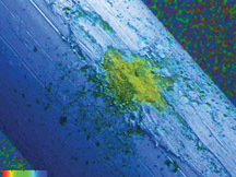
A thin layer of oxide was found to be forming on the injector male
pin terminal at the point where it contacts the female harness connection.
Invisible to the naked eye, “fretting corrosion” was found
on a majority of the NTF injector terminals (fig.
2).
“Fretting” describes a tiny rubbing motion that occurs between two
surfaces (usually on the order of 10-100 microns). “Fretting corrosion” refers
to a build up of insulating, oxidized debris that forms on electrical connections
due to a fretting action at the contact points. Injector vibration, engine vibration,
and electrical harness movement are contributors to the fretting motion.
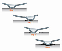
Refer to the accompanying illustrations (fig. 3).
Step 1 shows the tin oxide layer with clean tin-on-tin contact, resulting in
a stable connection.
Steps 2 and 3 show further progression of fretting corrosion (formation of oxide
layer).
Step 4 shows the contact point after numerous fretting cycles, resulting in an
unstable electrical connection.
The amount of oxide build-up determines how drastic the effect will be on the
injector circuit. Worst case is a total loss of continuity in the connection
resulting in P0200 (Injector Circuit Fault) and P0300 (Misfire) codes being set.
If the oxides create a high resistance circuit, insufficient current will be
available to properly open the injector, resulting in unstable fuel delivery
and ultimately a P0300 DTC. High resistance in the circuit will not necessarily
set a DTC P0200.
Keep in mind that a connection with fretting corrosion is unstable. Because movement
causes fretting, any vibration may create a condition where the connection varies
from an open circuit, to a high resistance connection, to a good connection.
What To Do?
Disconnecting and reconnecting the injector connector will temporarily scrape
the oxides off, creating a good connection. This explains why replacing a suspected
faulty injector with a new injector appears to repair the condition. But, if
the conditions still exist for fretting to occur, it will eventually come back.
Using lubricant part number 12377900 (in Canada, 10953529) to coat the terminals
is the best preventative measure to take. This provides a lubricant for the terminals
as well as providing an oxygen barrier to guard against oxide formation.
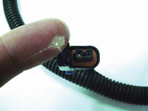
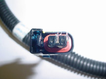
To apply the lubricant, gather a small amount (about the size of a BB) on the
end of your finger (fig. 4). Press it into the end of the disconnected female
connector, making sure to cover both cavities (fig. 5). Reconnecting the harness
connection onto the injector will wipe the lubricant onto the male terminal pins.
-
Thanks to Randy Pearl and Dave Sant |

figure
1 |
|
figure
2 |
|
figure
3 |
| |
figure
4 |
figure
5 |
|
|
|
| Breaking News
About Service Bulletins |
In
the past, your dealership has received an allotment of printed service
bulletins on a regular basis, in the Dealer World Delivery box. In
addition, many dealerships also subscribe to receive additional copies
to distribute to technicians. At the same time, service bulletins have
also been viewable on the Service Information (SI) website.
TIP: If you still do not have ID and password to access SI, contact your
Area Service Manager or call the Techline Customer Support Center at
800.828.6860.
By the end of June, 2003, there will be a change in the way printed bulletins
are distributed. Printed bulletins will no longer be sent automatically
to your dealership. You can continue receiving printed bulletins, at
the price of 10c per copy. Your service manager has received a Dealer
World subscription form on which to place your order. The subscription
will continue on a regular basis until you choose to change it.
Whether your dealership
chooses to subscribe to receive printed bulletins or not, here’s
how to find bulletins on SI.
- Go to the website at http://service.gm.com.
- Click on Service Information.
- Put in your ID and password.
- Click on Number Search if you know the number of the bulletin.
- Click on Latest News if you want to read a list of the most recent
bulletins issued (past 8 weeks). These are organized by Bulletins,
Campaigns and Preliminary Information. Within categories, the information
is organized
by typical SI topics, such as Engine, Steering, HVAC and so on.
- Click on the Y+P+K button if you want to see bulletins that pertain
to a specific year, platform and keyword.
Some printed material will continue to come, whether you subscribe
to printed bulletins or not.
1. Warranty Administration bulletins and Advanced Service Information
bulletins will continue to be distributed in printed form for the
foreseeable future.
2. Your dealership will receive a printed summary of bulletins
issued, every two weeks. This parallels the information on the
Latest News
page of the website.
3. And finally, your dealership will receive a blue-bannered
printed bulletin called the Field Product Reminder, every two
weeks. This
will contain a list of “Fix It Right The First Time” items
for cars and trucks. This list is also being repeated on the
rear cover
of TechLink each month.
TIP: You may want to remind owners that they can subscribe to
receive service bulletins as well. Every owner’s manual
contains the necessary ordering information.l.
- Thanks to Alan Srodawa and Frank Flees
|
| |
|
|
Additional
Training Sites Coming
|
In
the coming months, you will be able to get more hands-on training than
ever before. In an effort to help service technicians “fix it
right the first time” and to achieve their training requirements,
GM Service Technical College (STC) is opening an additional four satellite
locations (fig. 6) to supplement the current 23 training locations
nationwide.
Each satellite training site selection was based on population and dealer
density, and input from GM field personnel. New satellite locations include:
- North Central -- Stark State College of Technology, Canton, OH
- North East -- Mass Bay Community College, Ashland, MA (Boston)
- South Central -- St. Philip’s College, San Antonio, TX
- South East -- J. Sargeant Reynolds Community College, Richmond, VA
GM STC will be providing training dates and schedules in the coming weeks,
as information becomes available.
For questions, visit the GM Training Website (GM TW) at www.gmcommontraining.com
and select “Contact Us.”
- Thanks to Lisa Kennedy |

figure
6
|
|
|
| return
to Table of Contents |
|
| A/C
Sealant Detector |
TIP: Before connecting a suspect system to your equipment, first test the
refrigerant for the presence of stop-leak.
The GE-47548 Sealant Detector consists of a high-side coupler with a
built-in flow restriction cartridge, a hose, and a flowmeter (fig.
7).
There are two high-side couplers, one for R12 and one for R134a. Each
one has provision for the installation of a disposable flow restriction
cartridge. Before use, apply water to the cartridge, using the dispenser
provided.
The tool is connected to the A/C system’s high side. A small amount
of refrigerant is allowed to flow through the tool, causing the ball
in the flowmeter to rise. After two minutes, if the ball remains high,
there is no sealant in the A/C system. If the ball drops within this
time, it indicates that sealant in the refrigerant has cured in the passageway
in the cartridge, causing flow to drop or stop.
A plugged cartrige must be replaced before the tool is used again.
The GE-47548 Sealant Detector is available through Kent-Moore.
-
Thanks to Dave Roland, Derek Trimble and Gary Halpern |
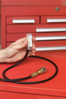
figure 7
|
| return
to Table of Contents |
|
| A/C
Refrigerant System Sealer and Leak Detection Guidelines |
Refer
to bulletin 03-01-38-001 for details. Here are the highlights.
Various A/C system sealers, stop-leak, and seal conditioners are available
to consumers and to the A/C repair industry. Because they are easily
obtained, there’s a likelihood that you will encounter a vehicle
with an A/C system contaminated by one of these products.
TIP: A GE-47548 Sealant Detector is now available from Kent-Moore. It
is discussed in an accompanying article.
Products Not Endorsed
GM Service Operations does not endorse or approve use of such products
in any GM vehicle. These products may damage A/C systems and service
equipment.
IMPORTANT: A/C systems contaminated with sealers, stop-leak, or seal
conditioners are not covered by GM New Vehicle Warranty or Replacement
Part Warranty.
A typical stop-leak sealant is carried through the A/C system in the
refrigerant oil. If a leak occurs, some of the sealant passes out of
the refrigerant system into the atmosphere. It cures in the presence
of moisture, which is supposed to “seal” the leak. If there
is moisture in the vehicle’s A/C system, or in the plumbing of
your A/C service equipment, the stop-leak can cure there, causing circulation
problems.
In addition to stop-leak products, there is another family of products
which is not recommended or endorsed. These are the seal conditioners,
which cause system o-rings and other rubber components to swell to stop
leaks.
These seal swellers cannot be detected using the GE-47548 Sealant Detector
or any other known tool at this time. Seal swellers can cause similar
problems once added to A/C systems. The sealer swellers also pose a potential
threat to recover/scavenger units, because they contain rubber o-rings
and other parts.
The Approved Approach
Various federal, state/provincial and local regulations prohibit recharging
an A/C system with known leaks. In support of these regulations, GM Service
Operations recommends using recommended leak detection devices to locate
leaks, and then using recommended procedures to repair
or replace leaking
components.
Flushing
Using GM-approved (refrigerant-based) system flushing on a contaminated
system can introduce these contaminants into the A/C service equipment,
which may cause equipment damage.
It may be necessary to replace all components affected by the additives
to correct a contaminated system.
-
Thanks to Dave Roland |
| return
to Table of Contents |
|
| Door
Hinge Repair |
Owners
of 1999-2003 Chevrolet Silverado and GMC Sierra may comment that
a door sags or is hard to open or close.
A door hinge pin and bushing kit is available from:
Ken-Co Industries LTD
Burlington, Ontario, Canada
phone 1.800.263.4283
fax 1.905.335.1829
email info@ken-co.com
attention Ken Spragg
website www.ken-co.com
Each door requires 2 kits. The minimum order is 6 kits.
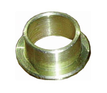
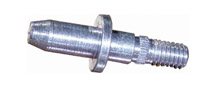
A kit includes 2 brass bushings (fig. 8), 2 zinc coated hinge pins (fig.
9), 2 nyloc locknuts, 1 washer, and instructions.
Using the kit (fig. 10) permits repairing and realigning the door without
having to cut off the hinge, and no painting is required.
-
Thanks to Steve Love |
figure
8
|
figure
9 |

figure
10 |
| return
to Table of Contents |
|
| Battery
Green Eye Eliminated

|
In
the next few months, you will begin seeing new vehicles equipped
with Delphi batteries that no longer have the “green eye” (built-in
hydrometer).
This is a rolling change which will eventually include all GM cars
and trucks. Service replacement batteries will be “eyeless” as
well, as current stock is depleted and replaced.
TIP: The green eye was never installed in the AGM battery, used in Corvettes
and the 2004 Pontiac Grand Prix, because these batteries do not contain
free liquid to operate the hydrometer.
State of Charge
You are of course familiar with the intended use for the green eye
-- indicating the battery’s state of charge. This information
is useful in determining whether a battery is charged, needs to be
charged, or
lacks sufficient electrolyte to permit charging.
The green eye information is largely redundant now that the Midtronics
J-42000-U conductance tester is in widespread use. This tester can analyze
a battery with a low state of charge, so long as it has sufficient voltage
to operate the tester.
There is another diagnostic test you can perform to determine the battery’s
state of charge, the Open Circuit Voltage (OCV) test.
Open Circuit Voltage Test
OCV may be used to estimate the state of charge. This method is generally
accurate +/- 10%. Temperature also affects OCV, so that must be taken
into account.
The voltmeter you use must be properly calibrated, capable of reading
to the nearest 0.01 volt, and accurate within +/- 0.005 volt.
The battery must be free of all current flow (that’s why it’s
called open circuit) -- it’s best to disconnect it entirely.
A battery becomes unstable for a period of time after it is charged
or discharged. So, it’s important to know what has happened to
battery before performing the OCV test.
If the battery has not been charged or discharged within 12 hours --
the OCV is fairly stable and the test can be performed using the OCV
vs % Charge table.
OCV |
%
Charge at 0°C
(32°F) |
%
Charge at 25°C
(75°F) |
12.75 |
100% |
100% |
12.0 |
100 |
90 |
12.60 |
90 |
75 |
12.45 |
75 |
65 |
12.20 |
65 |
45 |
12.00 |
40 |
20 |
If
the battery has been charged, discharged or used in a vehicle within
12 hours -- the OCV may not be stable enough for a reliable reading.
If the battery has been charged, you must first remove any surface
charge using a carbon pile. Discharge the battery at 300 amperes
for 15 seconds. Disconnect the pile, allow 15 seconds for recovery,
then read the OCV.
If the battery has only been discharged, just wait at least 15 seconds
for the voltage to stabilize after disconnecting the load before testing.
A battery with a 65% or greater state of charge is generally considered
charged enough to be returned to normal service.
TIP: If the battery will be used in slow traffic, short trips, or very
hot or cold weather, it should be at least 90% full charge before returning
to service.
If Charging is Required
The new “eyeless” batteries now include the battery’s
amp-hour (AH) rating on the label. This information can be useful in
setting up your battery charger. The AH rating was not previously available
for GM OE batteries.
TIP: Most battery replacement guides in the US will still be based
on the OE battery’s CCA and RC (Reserve Capacity) ratings. Don’t
confuse the RC and AH ratings when selecting a replacement battery
model – they are different tests.
- Thanks tozz |
| |
| |
|
return
to Table of Contents |
|
| Terminal
Repair Kit Update |
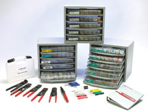
This
information will help you understand the J-38125-C Terminal Repair
Kit and use it more effectively (fig. 11).
Some definitions:
An electrical terminal is the formed metal attached to the end
of a wire to provide electrical connection with another wire or
with a component.
Groups of terminals are organized into molded plastic blocks called
connectors.
Groups of wires, with their terminals and connectors, are gathered
into wiring harnesses.
Differences Between Production and Service Terminals
Service terminals are not necessarily the same as production terminals.
A single service terminal may replace several production terminal numbers.
Service terminals are chosen so the crimp wings fit the crimp tools
in the J-38125-C. You should use the crimp matrix in the Terminal Repair
Kit Instruction Book for best results.
Service terminals may have more tin or gold content then the production
terminal.
Service terminals may have a higher contact force than the production
terminal. In the assembly plant, where actions are repetitive, connector
assembly effort is an issue that does not come up in service.
Where Do Service Terminals Come From?
Service terminals are NOT available from GMSPO. A parts bulletin IB03-044
has been issued to this effect.
All service terminals should be ordered from SPX (Kent-Moore) at 1.800.345.2233.
All components and tools of the J-38125-C Terminal Repair Kit should
be ordered from SPX (Kent-Moore) at 1.800.345.2233.
It will be important to keep the complete J-38125-C Terminal Repair
Kit in proper order and stocked with terminals and tools, as more wiring
suppliers make their appearance in GM vehicles.
What’s the Distinction Between Wiring Harness Suppliers
and Connection System Suppliers?
Wiring harness suppliers build harnesses according to engineering specifications.
This means that a wiring harness supplier will use their own connection
system, plus those from other suppliers, so most harnesses contain
an assortment of connection systems.
This is a list of connection system suppliers used by GM. Some of these
companies are also wiring harness suppliers.
- AFL/EPC
- Bosch
- Cinch
- Delphi
- FCI
- JAE
- JST
- Koste
- Molex
- Sumitomo
- Tyco/AMP
- Yazaki
There is an effort in engineering to limit the proliferation of connection
system suppliers.
How Are All These Terminals Organized in the J-38125-C Terminal Repair
Kit?
There are five Wiring Suppliers for GM Power and Signal Distribution
(PASD) systems:
- AFL
- Delphi
- Lear
- Sumitomo
- Yazaki
These five supply the wiring used in North American-engineered platforms.
TIP: Some platforms are not engineered in North America. These include
the International Joint Venture Vehicle Platforms (IJVP): Vibe, Tracker,
Isuzu-supplied MD trucks, and vehicles with pre-wired Honda engines.
Service terminals for these are not included in the J-38125-C Terminal
Repair Kit.
The J-38125-C Terminal Repair Kit was originally a Delphi terminal
repair kit only. Now we have Delphi trays, Lear trays, Sumitomo trays
and Yazaki
trays, with AFL to be added.
Trays are named for the five wiring harness manufacturers. If a harness
manufacturer also makes terminals, their terminals are in their trays.
Terminals from other terminal manufacturers may also be included
in the harness makers’ trays.
AFL/EPC is the wiring supplier for the ‘04 Corvette, and two other
future programs. An AFL tray will be added to the Terminal Repair Kit
in the near future and any AFL terminals used for the first time in the ‘04
Corvette will be in that tray.
Delphi is the wiring supplier for every truck platform except the M/L
Van. Delphi is also the wiring supplier for most car platforms. Delphi
has the most history with GM and has the most trays in the Terminal
Repair Kit. Delphi trays may also contain service terminals from:
- Delphi
- Bosch
- FCI
- JAE
- JST
- Molex
Lear is the wiring supplier for the M/L Van, and the Saturn Vue and
Ion. Lear makes no terminals or connection systems. Instead, they use
terminals
from other suppliers. Lear trays contain service terminals from:
- Bosch
- Molex
- Tyco/AMP
TIP: Tyco/AMP terminals used by all wiring harness suppliers, so a
Tyco/AMP terminal may be in any tray.
Sumitomo is the wiring supplier for a future truck program. Sumitomo
makes terminals and connection systems. The Sumitomo tray will be filled
in the near future.
Yazaki is the wiring supplier for the Cadillac CTS, the ‘04
Cadillac SRX and a future Cadillac program. Yazaki also makes terminals
and connection
systems. There are 5 trays of Yazaki service terminals. The Cadillac
CTS was first to use these terminals. Yazaki trays contain service
terminals from:
- Yazaki
- Kostel
- Molex
- Tyco/AMP
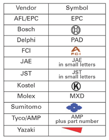
How Do You Know Whose Terminal You’re Looking At?
You can get your clue from the connector from which it was removed.
Look on the connector for these identifying symbols. Many are small
or difficult
to find.
Connector Symbols
All
suppliers use their own connection systems when they can, but most
will have a high Delphi connector content, because GM still uses
a high number of Delphi components.
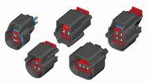
What’s Coming?
A Federal Agency called USCAR sets test and footprint standards for
all US vehicle manufacturers. The effort to comply with USCAR will
be seen in all GM vehicles. This will ultimately result in connection
systems that will have the same look and feel, regardless of the supplier
(fig. 12). There is even an effort to have a GM-common terminal in
several popular sizes, which will greatly reduce the increasing number
of service terminals we now see in the J-38125-C Terminal Repair Kit.
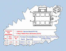
Information included in SI is also being revised. A pilot for a new
connector end view is planed for the ‘04 Cadillac XLR service
information (fig. 13). This connector end view will give you the service
terminal number that is in the J-38125-C Terminal Repair Kit.
TIP: Because service terminals are not stocked in GMSPO, service terminals
have supplier part numbers. The new connector end view will for the
first time give you the real connector or pigtail part number, which
is stocked in GMSPO. This connector end view may take some time to
make its appearance in all the service information but every effort
is being made to do so.
A Word About Pigtails
A pigtail consists of a connector with terminals and short lengths
of wire already installed. They are available for numerous electrical
devices (up to 8 cavities), and are intended to be spliced in place
of a damaged connector.
Pigtails are sold through the AC Delco side of GMSPO. A GM Dealer parts
department can find a pigtail by application (2003 Cavalier generator,
for instance) but not by description (4-way female Metri-Pack 150 series).
AC Delco Catalog 16A-200 has a complete list and pictures of pigtails.
Call 1.800.ACDELCO (1.800.461.8606 in Canada) to find your local AC
Delco Parts distributor, who can assist you in obtaining a catalog.
There is also an AC Delco web site www.acdelco.com with online catalog
that will help, not only for pigtails but also for other items.
-
Thanks to John Roberts |
figure
11 |
| |
figure
12 |
figure
13
|
| return
to Table of Contents |
|
| Oil
Life System Reset Procedures -- Trucks |
Many
GM cars and trucks are equipped with an oil life system which determines
when an oil change is required. After the oil has been changed, it’s
necessary to reset the system.
Procedures for resetting 2001 through 2004 trucks are published here.
Passenger cars were published last month.
The information for this article is the same as you will find in the
applicable owner or service manual.
To find this information in SI:
- Select the vehicle
- Select category General Information
- Select category Maintenance and Lubrication
- Select category Maintenance and then GM Oil Life System-Resetting.
You may be able to use the Search function using the words Oil Life System
Resetting.
2001 - 04 Aztek
2002 - 04 Rendezvous
If the vehicle does not have the optional Driver Information Center (DIC)
do the following:
1. With the ignition key in ON but the engine off, fully push and release
the accelerator pedal slowly three times within five seconds.
2. Turn the key to OFF.
3. If the CHANGE ENGINE OIL message comes back on, the engine oil life
monitor has not reset. Repeat the procedure.
If the vehicle has the optional DIC, do the following:
1. Turn the ignition to ON with the engine off.
2. Press the MODE button until the DIC reads OIL LIFE LEFT/HOLD SET TO
RESET.
3. Press and hold the SET button until 100% is displayed.
You will hear three chimes and the CHANGE ENGINE OIL message will go
off. If the CHANGE ENGINE OIL message comes back on, the monitor has
not reset. Repeat the procedure.
2001 - 04 Montana
2001 - 04 Silhouette
2001 - 04 Venture
1. With the ignition key in RUN but the engine off, repeatedly push the
trip/reset button until OIL is displayed on the Driver Information Center.
2. Once OIL is displayed, push and hold the trip/reset button for five
seconds. The number will disappear and be replaced by 100 (indicating
100% oil life remaining).
3. Turn the key to OFF.
4. If the change engine oil message comes back on, the engine oil life
monitor has not reset. Repeat the procedure.
2002 - 04 Bravada
2002 - 04 TrailBlazer
2002 - 04 Envoy
2004 Ranier w/o DIC
1. Turn the ignition key to RUN with the engine off.
2. Fully press and release the accelerator pedal three times within five
seconds.
3. If the CHANGE ENG OIL light flashes for five seconds, the system is
reset. If the light does not flash, repeat the procedure.
2004 Ranier with DIC
1. Press the fuel information button until ENGINE OIL LIFE appears in
the display.
2. To reset the monitor, press and hold the select button while ENGINE
OIL LIFE is displayed.
2004 Canyon
2004 Colorado
1. Display ENGINE OIL LIFE on the DIC.
2. Press and hold the select button. The oil life will change to 100%.
3. Turn the key to OFF.
If the CHANGE/OIL message comes back on when you start the vehicle, the
engine oil life system has not reset. Repeat the procedure.
2004 SSR with DIC
1. Press the fuel information button until ENGINE OIL LIFE appears in
the display.
2. To reset the Oil Life System, press and hold the select button while
ENGINE OIL LIFE is displayed.
2001 - 04 Sierra
2002 - 04 Sierra Denali
2001 - 04 Silverado
2001 - 04 Yukon and Yukon XL
2001 - 04 Tahoe and Suburban
2001 - 04 Escalade
2002 - 04 Escalade EXT
2002 - 04 Avalanche
2001 - 04 Yukon Denali
2003 - 04 Hummer H2
2003 - 04 Express
2003 - 04 Savana
1. Turn the ignition to RUN but with the engine off.
2. Fully push and release the accelerator pedal slowly three times within
five seconds.
3. If the Change Oil Soon light flashes, the system is resetting.
4. Turn the key to OFF.
5. Start the vehicle.
6. The oil life will change to 100%.
7. If the Change Oil Soon light comes back on, the system has not reset.
Repeat the procedure.
2001 - 04 B7 Chassis Medium Duty
1. Turn the ignition to START but with the engine off.
2. Fully press and release the accelerator pedal three times within 10
seconds.
3. If the CHANGE OIL light flashes for five seconds, the system is reset.
4. If the light does not display for five seconds, you will need to reset
the system again.
2003 - 04 560 C-Series
1. Turn the ignition to RUN but with the engine off.
2. Fully press and release the accelerator pedal three times within 10
seconds.
3. If the CHANGE OIL light flashes for five seconds, the system is reset.
4. If the light does not display for five seconds, you will need to reset
the system again.
- Thanks to Jerry Garfield |
|
|
| return
to Table of Contents |
|
| HVAC
Afterblow Enable Procedure |
TIP: This is season-related information for many GM vehicles.
Operation of the blower motor after the engine has been turned off dries
the evaporator core, which reduces the amount of microbial growth, a
source of undesirable odors.
1998-2003 Cadillac Seville and 2000 Cadillac Deville
TIP: The afterblow mode can be enabled using the scan tool.
1. Connect the Scan Tool.
2. With the engine OFF, turn the ignition ON.
3. Select Instrument Panel Module.
4. Select Special Functions.
5. Select Miscellaneous Test.
6. Select IPM recalibration.
7. Select YES to enable afterblow.
2001-03 Cadillac Deville
TIP: The afterblow mode can be enabled using the scan tool.
1. Connect the Scan Tool.
2. With the engine OFF, turn the ignition ON.
3. Select Instrument Panel Module.
4. Select Special Functions.
5. Select Set Options.
6. Select Afterblow.
7. Select Yes to enable the afterblow.
This information can be found in SI documents 667536 and 784027.
Additional Vehicle Information
Information on enabling the afterblow mode on the following vehicles
will also be available in SI.
2003 - 2004 Cadillac CTS
2004 Cadillac SRX
2004 Chevrolet Impala
2004 Chevrolet Monte Carlo
2000 - 2004 Buick LeSabre
2000 - 2004 Buick Park Avenue
2000 - 2004 Pontiac Bonneville
2004 Pontiac Grand Prix
2001 - 2003 Oldsmobile Aurora
Some other vehicles have relay kits available through GMSPO as a dealer
installed feature.
-
Thanks to GM Technical Assistance |
| |
|
return
to Table of Contents |
|
| Squeak
Going Over Bumps |
Owners
of some 2003 S-10 and Sonoma Crew Cab models may comment that a high
pitch squeak can be heard outside and underneath the rear of vehicle
when driving over bumps. The park brake cable may contact the mounting
bracket. To correct the condition, secure the park brake cable away
from the mounting bracket.
-
Thanks to GM Technical Assistance |
| return
to Table of Contents |
|
 Car
Issues – Fix It Right The First Time Car
Issues – Fix It Right The First Time |
Model
Year(s) |
Vehicle
Line(s) --
Condition |
Do
This |
Don’t
Do This |
Reference
Information / Bulletin |
1998-2004 |
J,
N, W, H cars and Trailblazer, Envoy, Blazer, Jimmy, Bravada – Sunroof
concerns |
Refer
to diagnosis procedures and replace only discrepant parts |
Replace
entire sunroof module |
Bulletin
being published – refer to parts
catalogue information |
2003 |
CTS
-- Service Stability System. DTC C1286 |
Reprogram
EBCM |
Replace
steering wheel position sensor |
02-05-25-004 |
2000-2003 |
Cavalier,
Sunfire, Grand Am, Alero, Malibu – Fuel gage accuracy
and pump concerns |
Replace
sensor card for fuel gauge accuracy issue |
Replace
the fuel sender / pump assembly |
01-06-04-008D |
1999-2003 |
Grand
Am, Alero – Door glass clip breakage |
Replace
sash clip only |
Replace
entire door glass assembly for broken clips |
01-08-64-018 |
1997-2003 |
Grand
Am, Alero, Malibu – Brake pulsation |
Turn
rotor and use brake align procedure |
Replace
rotors for pulsation |
00-05-23-002
01-05-23-001
Know How 15040.01B |
1997-2003 |
Venture,
Montana, Silhouette – Windshield water leaks |
Use
correct diagnosis procedures described in service bulletin |
Assume
that leak came from the windshield sealing |
01-08-57-006 |
1997-2003 |
Century,
Regal – HVAC “Auto” light function |
Normal
in full heat or cold setting |
Replace
HVAC control head for "Auto" light |
99-01-39-007B |
2001-2002 |
Corvette
- Fuel gauge goes to empty intermittently |
Install
revised software |
Replace
fuel senders or I/P cluster |
2002
MY 02-06-04-010, 2001 MY Software released, bulletin not updated |
2003 |
All
cars with 4T65E and 4T80E – Code P0742 |
Replace
TCC PWM Solenoid |
Replace
transmission or valve body assembly |
02-07-30-039B |
2003 |
DeVille
with 4T80E Transmission - Code P0503 or Speedo Inop |
Reposition
coolant hose clamp and repair chafed wire |
Replace
vehicle speed sensors |
03-06-04-013 |
|
| return
to Table of Contents |
|
|
 Truck
Issues – Fix It Right The First Time Truck
Issues – Fix It Right The First Time
|
Model
Year(s)
|
Vehicle
Line(s) --
Condition
|
Do
This
|
Don’t
Do This
|
Reference
Information / Bulletin
|
2003
|
C/K
Fullsize Pickups & Utilities -- Mirror Loose
|
Cycle
mirror
|
Replace
DL3 power folding mirror
|
03-08-64-010 &
Parts Restriction
|
1999-2002
|
C/K
Fullsize Pickups & Utilities -- Throttle Body
|
Clean
throttle body adjust blade and insert plugs
|
Replace
throttle body for idle instability or increased accelerator pedal
effort
|
02-06-04-054B & Parts
Restriction
|
2003
|
C/K
HD Silverado, Sierra, G Savana, Express >8600GVW -- ABS Lamp
On
|
Re-flash
for code C0550
|
Replace
ABS module
|
TIS
2000: 3.0 & 4.0
Service VME
|
2002-2003
|
Envoy,
Envoy XL, Bravada, with G67m -- Low in Rear
|
Replace
sash clip only
|
Replace
air suspension compressor
|
02-03-99-001
|
2002-2003
|
TrailBlazer,
TrailBlazer EXT Envoy, Envoy XL, Bravada -- Outside Rear View
Mirror Erratic Return
|
Replace
mirror actuator & reprogram module
|
Replace
OSRVM
|
02-08-64-008
02-08-64-021
|
1999-2003
|
C/K
Fullsize Utilities -- Sunroof
|
Install
clip or mechanism kits
|
Replace
sunroof
|
02-08-67-009
|
1999-2003
|
C/K
Fullsize Pickups & Utilities -- Noise on Steering
|
Lube
I-Shaft
|
Replace
I-Shaft
|
00-02-35-003B
|
1999-2003
|
TrailBlazer,
Envoy, Bravada,
without G67 -- Moan Boom
|
Replace
rear coil springs
|
Rear
axle vibration boom noise that can result in vehicle repurchase
|
02-03-09-002A
|
2002-2003
|
TrailBlazer,
TrailBlazer EXT -- Loose or Wavy Fascia
|
Repair
fascia
|
Replace
front fascia
|
02-08-62-001
02-08-62-004
|
2002-2003
|
TrailBlazer,
TrailBlazer EXT, Envoy, Envoy XL, Bravada -- Tail Light
|
Replace
tail lamp circuit board
|
Replace
rear tail lamp assembly, for brake light
|
Service
VME to use service part, listed in GMSPO catalog
|
|
| return
to Table of Contents |
|
|
| Know-How
Broadcasts for July |
| |
 |
| Know-How
Broadcasts for July |
|
Emerging
Issues
|
July
17, 2003
|
9:00
AM, 12:30 PM,
3:30 PM
Eastern Time
|
|
10270.19D – 2004
Chevy/GMC Truck New Model Features
|
July
31, 2003
|
9:00
AM, 12:30 PM,
3:30 PM
Eastern Time
|
| -
Thanks to Tracy Timmerman |
|
|
| return
to Table of Contents |
|
|
|
