| |
 |
Note: Clicking
on any picture or illustration will open a larger version of that art.
|
|
Generation
6 OnStar |
OnStar launched
new and improved Generation 6 hardware in March, as a mid-year change
on the vehicles listed in the accompanying table. New OnStar hardware
is labeled System Type: Analog/Digital on the window sticker. Other
vehicles will roll out throughout the 2004 calendar year (fig.
1).
Here are some of the significant changes.
Dual Mode
The OnStar Gen 6 system functions on both digital and analog cellular
networks. This takes advantage of the growing digital cellular markets
around the country and further maximizes the coverage area.
In a digital market, the OnStar Vehicle Communication Interface Module
(VCIM) uses a different retry strategy to make a connection to the OnStar
call center. The Module makes multiple attempts to contact the OnStar
call center, using multiple digital and analog cellular providers. This
may take some additional time to make a connection.
TIP: When diagnosing
a customer’s OnStar “no connect” concern, be sure
to wait until the system plays either of the embedded wav files: “OnStar
request ended” or “Unable to contact OnStar.”
Digital Standby Mode
This is an enhancement to the traditional OnStar wake-up cycle. It allows
OnStar to provide Outbound services much more quickly.
On all previous generations, when the vehicle is off, the OnStar module
transitions out of sleep mode to low power mode for one minute out of
every ten minutes. During these one-minute periods, OnStar can contact
the car and unlock the doors.
With digital stand-by mode, if the vehicle is parked in a digital cellular
market, the OnStar system transitions to digital stand-by for 8 hours.
This power mode allows the car to be contacted by OnStar without having
to wait up to 9 minutes for the next wake-up cycle. Once the 8 hours
have elapsed, the vehicle switches to the traditional wake-up cycle
for the balance of the 48 hour period.
New Voice Recognition Engine
OnStar Gen 6 features an improved voice recognition engine. For those
service customers who have experienced difficulty using OnStar Voice
recognition, this system promises noticeable improvement.
A significant feature of this new voice recognition system is continuous
voice dialing. Simply say the entire phone number including the area
code at a natural talking speed, continuously, without pauses (for example:
2225551212).
When you are finished saying the number, the OnStar system repeats the
entire phone number and asks if the number is correct.
Refer to the new OnStar Owner’s Guide or the new OnStar Quick
Reference Card in the glove box of any OnStar Gen 6 equipped vehicle
for details.
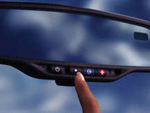
OnStar Operation in Unconfigured Vehicle
With the introduction of Gen 6, OnStar has turned all the voice prompts
on. This means that on an unconfigured vehicle, you can hear and use
all of the voice recognition features, up to but not including actually
making a call.
TIP: This is
normal and should not be considered a fault.
On an unconfigured vehicle, here’s what happens when the blue
button is pressed twice (fig. 2). You will
hear, ”Hello. What would you like to do?” If you say “talk
to an advisor,” OnStar will conntect to an enrollment advisor.
If you say “listen to the demonstration,” OnStar will begin
the new Automated Customer Demo. This will identify the vehicle being
driven, state where the vehicle is located (GPS location), and perform
a real-time door unlock demonstration.
When the vehicle is enrolled and configured upon delivery, the customer
will get 30 complimentary Personal Calling minutes to make and receive
calls.
TIP: Service
personnel may want to store a “call Service” nametag in
the system for customer convenience. Refer to the OnStar glove box material
for complete instructions for storing nametags.
TIP: To determine
whether a customer’s OnStar system is active, type the VIN into
VIS.
Additional Customer Education Required
This new generation of OnStar hardware is a significant enhancement
and will be extremely well-received by both current and new customers.
TIP: While the
new voice recognition system greatly improves the usabilty of the system,
current OnStar users who have grown accustomed to speaking one digit
at a time to dial a phone number may not understand the need to speak
the entire phone number continuously without pauses.
Should your service personnel receive a complaint that Voice Dialing
won’t work correctly, make sure the customer is familiar with
the continuous dialing feature, before diagnosing potential concerns
with the OnStar system.
Placing a Phone Call Using OnStar Personal Calling (OPC)
The following table explains how the new OnStar Personal Calling system
compares with the previous system that is still available on earlier
build vehicles.
-
Thanks to Dale Tripp
| Current
OnStar Hardware |
| What
You Do |
What
You Hear |
| 1.
Press |
 |
"OnStar
Ready” |
| 2.
Say "Dial" |
"Number
please" |
| 3.
Say the phone number to be dialed, one digit at a time |
OnStar will
confirm each digit by repeating it back to you |
| 4.
When finished, say "Dial," again |
"Dialing;"
your call will be connected |
| New
OnStar Hardware |
| What
You Do |
What
You Hear |
| 1.
Press |
|
“OnStar
Ready” |
| 2.
Say "Dial" |
"Phone
number to dial please" |
| 3.
Say the entire phone number you wish to dial, all at once, with
no pauses |
OnStar will
repeat the number, then ask "Yes" or "No" |
| 4.
Say "Yes" (say "No" to try again) |
"Dialing;"
your call will be connected |
| Production
Timing of First Quarter, 2004 Calendar Year |
| 2004 Model
Year Vehicles |
| Buick |
| -
Rainier |
| -
Rendezvous |
| Cadillac |
| -
Escalade ESV, EXT |
| Chevrolet |
| -
Avalanche |
| -
Trailblazer |
| -
Trailblazer EXT (XLT) |
| -
Silverado |
| -
Tahoe |
| -
Suburban |
| GMC |
| -
Envoy, Envoy XL, XUV (XUT) |
| -
Sierra |
| -
Yukon, Yukon Denali, Yukon XL, Yukon Denali XL |
| Hummer |
| -
H2 |
| Pontiac |
| -
Aztek |
|
|
figure
1 |
|
|
| |
|

figure 2
|
| return
to Table of Contents |
|
|
| TIS
2 Web |
GM Service and Parts Operations is launching a new version of the TIS
diagnostic/programming application, called TIS 2 Web.
This follows the concept established by SI on the web. The future direction
for all service software applications is to make them available from
central internet sites rather than locally at each dealer’s server
or loaded on the Techline PC.
The advantages are:
- increased speed of updates
- consistent software versions for all users
- improved maintenance and enhancements
- improved support
- ability to gather user feedback easily.
What’s Required for Access?
- Techline PC meeting minimum hardware requirements (See http://service.gm.com/techlineinfo/techlinepc.html
for hardware requirement details).
- High speed internet connectivity at the Techline PC.
- Individual DealerWorld ID and password for each technician.
TIP: DealerWorld
IDs are managed by the dealership’s Partner Security Coordinator
(PSC). Security parameters in place will not allow ID/PW credentials
to be shared.
- Download and installation of Java 1.4.2 and Webstart to the Techline
PC. A link to the download can be found under the Help icon in the upper
right corner of the web site.
First Phase of TIS 2 Web
The first phase of the release is Software Download. Just as with the
current version of TIS, Software Download allows a technician to download
Tech 2 updates to their Techline PC and then update their Tech 2 diagnostic
tools. The big difference is that the download is from an internet site.
Future Phases
The next phase of the release will be Service Programming System (SPS).
This release should be expected in mid-2005, with Tech 2 View and Snapshot
Upload/Display to follow.
TIS 2 Web will be maintained in parallel with the TIS GM ACCESS version
until the GM ACCESS servers are decommissioned sometime in 2006.
TIS 2 Web will be updated on the same release schedule as TIS.
Getting familiar with using TIS 2 Web as an internet based service resource
will help technicians become familiar with using GMSPO internet resources,
improving their efficiency, and being able to “Fix It Right the
First Time.”
Calling for Assistance
If at any time you need assistance with the TIS 2 Web Software Download,
please contact the Techline Customer Support Center (TCSC) at 1.888.337.1010,
prompt 3. Saturn Retailers may use 1.888.7SATURN for assistance.
-
Thanks to Mike Waszczenko |
|
|
|
|
Equinox Clarification |
This
information is intended to clear up some misunderstanding about the
All Wheel Drive system, mentioned in the April issue of TechLink. The
misunderstanding stems from the fact that both systems use the Versatrak™
transfer case (also called Power Take-off Unit or PTU), attached to
the transaxle.
While there are similarities between the Equinox system and the Versatrak
system used on other vehicles, the term Versatrak does not apply to
Equinox.
The Equinox All Wheel Drive system uses one viscous coupling to share
power between front and rear wheels, while the Versatrak adds a second
coupling to share power from side-to-side on the rear wheels.
- Thanks to Ange Girolamo |
|
|
return to Table of Contents |
|
| GM
LAN or Class 2? |
There
is quick method to identify module protocol and it can be found in SI.
“Build” the vehicle, then select Service Manuals/Bulletins.
In the keyword field, type "data link" and click on Enter.
Select Data Link Communication Description and Operation.
Scroll to the bottom of the document. GM LAN and Class 2 components
are listed.
TIP: For a complete
Model Year 2005 Communication Protocol Table, go to the TechLink website.
Click on the Reference Guides tab, then scroll down to the protocol
table and click on the link.
For each 2005 vehicle, the table lists engine RPO, name, and family,
transmission name, transfer case name, Tech 2 data release number, production
date, diagnostic strategy, PCM/ECM name and communication protocol,
and body/chassis communication protocol.
-
Thanks to Mark Stesney |
| |
| return
to Table of Contents |
|
| Obtaining
Radio Part Number |
You can use your Tech 2 to obtain the part number of the radio in a
vehicle.
For class 2 vehicles, follow this path (typical):
- Diagnostics
- Build vehicle
- Body
- Radio
- I D Information
- Module Information
- 8 Digit GM Part Number
TIP: The module
list is arranged alphabetically. So, when scrolling the list, you will
see Digital Radio Receiver early in the list and Radio later in the
list.
If you select Digital Radio Receiver, you will obtain the part number
for the remote-mounted XM satellite receiver.
-
Thanks to Jim Hughes |
| |
| return
to Table of Contents |
|
| Oldsmobile
Production Has Ended |
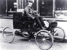
General
Motors announced in December 2000 that the Oldsmobile line of vehicles
would be discontinued sometime during the 2004 model year.
The dates of the end-of-production of the 2004 models was Bravada on
January 16 and the Silhouette on March 26. GM, on purpose, decided that
Oldsmobile production would end in the city it began, Lansing, Michigan
(fig. 3). A total of 35,229,218 Oldsmobiles
were built since 1897 and of those 14,458,756 were built in Lansing.
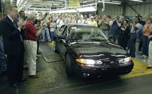
On April 29, 2004, at 10:00 AM, the last Oldsmobile built drove off
the assembly line of the South Assembly Plant of the Lansing Car Assembly
complex (fig. 4). The driver was plant
employee Rick Parr, front passenger was George Nahas, President of the
Oldsmobile Dealer Council, backseat passengers were plant employees
Al Cooper and Bill Schleicher. All plant employees who worked on the
last Alero had already signed their names to the under side of the hood
and the rear compartment lid. GM will retain ownership of the last Oldsmobile.
Presenters at the end-of-line ceremony were Amy Farmer, Plant Mgr, Officials
of UAW Locals 602 and 652, and former Oldsmobile Gen. Mgr. Darwin Clark.
The final Final 500 Alero was then driven by Doug Stott, Oldsmobile
Product Mgr, to the R.E.Olds Transportation Museum where it will be
on display with all the other Final 500 models and significant older
Oldsmobile models until August 31, 2004. About 20 Oldsmobiles belonging
to OCA and Museum members were also on display outside the Museum.
-
Thanks to a sad Jerry Garfield |
figure
3 |
| 
figure
4
|
| return
to Table of Contents |
|
| Automatic
Air Bag Suppression Systems |
TIP:
For background, you may wish to refer to the October 2002 TechLink article
“New Air Bag Features in 2003 -- Full-Size Pickup Trucks.”
ROLL OUT
With a few exceptions, FMVSS (Federal Motor Vehicle Safety Standards)
requires all vehicles sold in the U.S. to be equipped with automatic
passenger airbag suppression by model year 2006.
GM will use three different systems, and each has a different sensing
method. Here is how the various vehicle lines will roll out for 2005.
Model
Year |
Vehicle |
Type |
| 2003 |
C/K trucks |
Gel-filled |
| 2005 |
Cadillac CTS
Buick LaCrosse
Buick Rendezvous
Buick Terraza
Buick Rainier
Chevy Uplander
Chevy Trailblazer
Saturn Relay
GMC Envoy
Pontiac Montana
Isuzu Ascender
Saab 9-7 |
Force Sensing
Capacitive
Gel-filled
Gel-filled
Gel-filled
Gel-filled
Gel-filled
Gel-filled
Gel-filled
Gel-filled
Gel-filled
Gel-filled |
DESCRIPTION
AND OPERATION
Classifications
The front passenger air bag is enabled or suppressed according to the
classification of the occupant of the front seat.
| Child seat |
suppress |
| Empty seat |
suppress |
| 6 year old
or smaller |
suppress |
| 5th percentile
female and larger occupant |
enable |
Common Features
The three passenger presence systems (PPS) use different sensing methods,
but the overall purpose and function are the same for all three.
TIP: Refer to
the following sections for a detailed description of each sensing method.
The PPS monitors the occupant on the front outboard passenger seat and
communicates the status to the sensing and diagnostic module (SDM) whether
to enable or suppress the deployment of the I/P module.
If the PPS determines there is an empty seat, child seat, an occupant
below a specified threshold, or a current fault in the system, the PPS
module will send a suppress signal to the SDM to disable the I/P module.
If the PPS determines there is an occupant above the specified threshold,
the PPS module will send an enable signal to the SDM to enable the I/P
module.
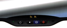
The PPS module will notify the occupants of the enable/disable status
by turning on one of the passenger airbag status indicators located
on the rear view mirror or instrument panel (fig.
5).
The PPS monitors itself for faults and will set a diagnostic trouble
code (DTC) if a fault is detected. The PPS will also notify the SDM
of the fault and the SDM will request the instrument panel cluster (IPC)
to turn ON the AIR BAG malfunction indicator located on the IPC.
The Tech 2 is used to determine what DTCs have been set by the PPS.
In the case of the gel-filled type and capacitive type systems, DTCs
are flashed on the rear view mirror or IP indicators. With the force-sensing
system, DTCs can be read on the scan tool display.
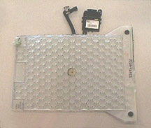
Sensing Method: Gel Filled Bladder (fig.
6)
This is the system introduced on 2003 C/K trucks.
TIP: For 2005,
the instrument panel disable switch is removed on any vehicle equipped
with an automatic airbag suppression system. It is still required on
vehicles above 8500 GVW without PPS.
The PPS consists of an electronic control module, silicone filled sensor
pad, pressure sensor, seat belt tension sensor (BTS), wiring harness,
and passenger air bag status indicators.
The silicone filled sensor pad is located under the passenger seat foam
cushion and is connected by a hose clamped to the pressure sensor. The
weight of the occupant sitting in the front passenger seat is measured
as a pressure change within the bladder by the pressure sensor. The
pressure sensor sends a voltage signal to the PPS module. The BTS monitors
the seat belt, mainly to detect if a tightly cinched child seat is present.
The ECU algorithm uses these inputs to determine the classification
of the occupant.
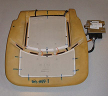
Sensing Method: Capacitive (fig. 7)
TIP: This is
the system being installed in the 2005 Buick LaCrosse.
The PPS consists of an electronic control module, sensor mat, wiring
harness and passenger air bag status indicators.
The sensor mat is made up of several flexible conductive metal strips
placed underneath the seat cushion trim and attached to the top surface
of the bottom seat cushion foam. These sensor strips transmit and receive
a low-level electric field. The weight of the occupant sitting in the
front passenger seat is measured as a change in current flow within
the sensor mat. The ECU algorithm uses this change in current flow to
determine the classification of the occupant.
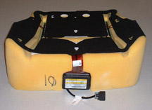
Sensing Method: Force Sensing Resistors (fig.
8)
TIP: This is
the system being installed in the 2005 Cadillac CTS.
The PPS consists of an electronic control module, sensor mat, wiring
harness, and passenger air bag status indicators.
The sensor mat is attached to the top surface of the bottom seat cushion
foam and is made up of many very thin force-sensing resistors, strategically
located across the surface. From these positions, this system can detect
the size and shape of the object in the seat. As the seat is loaded,
the resistance through cells lowers and the voltage through the mat
changes. From this, the ECU monitors the pressure profile of the occupant
to determine the proper classification.
AFTER-REPAIR TIPS
The following steps must be taken after a seat repair or system replacement.
Gel-filled Bladder Type
- Re-zero – Seat must be empty
- Use scan tool to command Re-zero
- Learns empty seat values
Capacitive Type
- Re-zero - Seat must be empty
- Use scan tool to command Re-zero
- Learns empty seat values
Force-sensing Resistor Type
- Preload Test - Seat must be empty
- Use scan tool to request preload test
- If preload is present, a DTC will set, specifying a particular zone
has a preload condition present. Preload may be caused by excessive
trim tension or seat heater mat has bunched in a particular zone. Straighten
out heater mat or stretch/massage trim to relieve tension. The preload
test must be re-performed until all preload is removed from the sensor
mat.
SERVICE TIPS
If the system fails, a service kit will have to be used. The
service kits are calibrated as an assembly. All components in the kit
must be used and not mixed with any of the old parts. There
may be multiple kits available for the particular vehicle. Make sure
to order the correct kit for the vehicle and seat options.
If any repair is performed to the seat bottom that requires
the seat bottom trim to be loosened, removed or replaced, a preload
test or re-zero procedure must be performed.
If a repair is done on the seat back, a preload test or re-zero procedure
may not be necessary as long as the seat bottom was not disturbed. The
service information for the particular vehicle will let you know when
a procedure will be necessary.
Accessories, such as aftermarket seat heaters, adding extra
foam under trim for comfort, or other seat modifications may cause the
system not to perform properly. These systems are designed
to detect various classifications of occupants. With added material
between the seat and the occupant, the system’s sensing capabilities
are reduced.
If passenger seat work is sublet to a trim shop, it is important
that you know what repairs are being done. It is the dealership’s
responsibility, when the repair is finished, to have the seat re-zeroed
or have a preload test performed, which a sublet shop will not be able
to perform.
HEATED SEAT TIPS
If the vehicle did not come with an OEM heated passenger seat,
an aftermarket heater cannot be added.
If the system has a heater assembly, the repair procedure may vary.
Read service information for the particular vehicle, to understand the
replacement procedure.
The capacitive system is calibrated with the heater mat. If the heated
mat fails, the entire PPS must be replaced. The other systems may or
may not require the heater mat to be replaced with the system, based
on the heater mat design. With suppression added, previous heater mat
replacement procedures may no longer be valid.
-
Thanks to Devin Koski |
| |
| |
| |
| |
| |
| |
| |
figure
5 |
figure
6 |
figure
7 |
figure
8 |
| |
| |
| |
| |
| |
| |
| |
| |
| |
| |
|
return
to Table of Contents |
|
| Pictorial
Format in SI -- Followup |
As
you start to use SI for 2005 vehicles, you will find that a few of them
will contain the new Pictorial format for mechanical procedures (see
TechLink, April and May 2004 for details).
If you'd like to provide your comments directly to the development team
for this new format, please send us an e-mail at pictorial.feedback@GM.com.
Our goal is to make improvements based upon your needs, so if you have
a suggestion or comment about this format, please drop us a line. Note
that this special e-mail is intended for Pictorial feedback only, so
please continue to use your normal process for letting us know about
incorrect or missing information.
- Thanks to Bob Scherer |
| |
| return
to Table of Contents |
|
| Gold
Bow Tie Emblem |
Certain cleaning substances used by some pre-delivery departments can
cause a discoloration of the gold bow tie appliqué on the 2004
Chevrolet Cavalier and the SSR (fig. 9).
A chemical intended to remove bug debris has been found to discolor
the bow tie. Avoid chemicals listing oxalic acid, dihydrate techorganic
acid or hydro-florides as an ingredient.
TIP: It is not
necessary to avoid using these chemicals to clean vehicles, but BE SURE
to avoid contact with the gold bow tie.
GM Brand Quality is working with the supplier to increase the durability
of the parts so they are more robust to cleaning agents. Closely inspect
your inventory of vehicles to determine if a potential issue exists.
If you notice discoloration, stop use of the chemical agent immediately,
and file a field product report.
-
Thanks to Steve Oakley |

figure
9 |
|
return
to Table of Contents |
|
| Active
Wheel Speed Sensor Diagnosiss |
TIP: Refer to
the October 2003 TechLink article regarding the operation of active
wheel speed sensors.
2004-05 Chevrolet Colorados and GMC Canyons with 4WAL ABS are equipped
with active wheel speed sensors. A DTC C0035 may be set for any of the
faults that will trigger a DTC C0035 on ABS systems that use conventional
wheel speed sensors. For instance, an open or shorted left front wheel
speed sensor, a missing left front wheel speed sensor signal, or an
erratic left front wheel speed sensor signal.
In addition, DTC C0035 will set when a short to voltage or short to
ground on the wheel speed sensor voltage supply circuit occurs on
either the left or right side front wheel speed harness. This
is because the EBCM internally supplies voltage to the left and right
wheel speed sensors from a single point. A C0040 will not set for any
wheel speed sensor supply voltage fault. Both C0035 and C0040 wheel
speed faults will continue to detect all other wheel speed sensor faults
in the usual way.
The service manual in being updated to reflect this issue. A Tech 2
software change was included in CD 3 on March 12. The software change
includes the following expanded DTC descriptor: C0035 Left Front Wheel
Speed Sensor Circuit or Front Sensor Supply Voltage Circuits.
-
Thanks to John Spidle |
|
|
|
return
to Table of Contents |
|
| Trailer
Wire Harness |
The location of trailer wire harness in the 2003-04 Chevrolet SSR owner's
manual is not specific. The trailer wire harness is located on the inside
of the left frame rail, between the tubular frame crossmember (just
behind the rear axle) and the crossmember (just in front of the trailer
hitch).
The wire harness is held in place by two gray wire harness retainers
and is taped to the convoluted tubing just rearward of the second wire
retainer. The black electrical tape must be removed to expose the wires.
The wires are blunt cut and have heat shrink insulation over the ends.
-
Thanks to Dan Oden |
|
|
|
return
to Table of Contents |
|
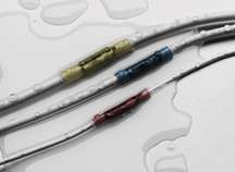
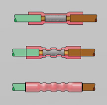
| Crimp
and Seal Connectors |
Take
a look in Tray 1 of your J-38125 Terminal Repair Kit. Three of the bins
contain pink, blue and yellow DuraSeal Crimp and Seal splice connectors
(fig. 10). Each is identified by its own
part number and is suitable for splicing wires of a specific gauge.
See the table below for details.
These connectors look simple, but they contain some significant technology
you need to know about.
Crimp and Seal splices are intended to join wires located in areas that
are subject to harsh environmental conditions such as temperature extremes,
immersion in fluids such as coolants, oil, and water, and exposure to
ultraviolet radiation.
There is a metal tube inside the Crimp and Seal splice. The tube is
knurled inside, to provide a low-resistance junction with the wires,
when the connector is properly crimped (fig. 11).
The outside of the DuraSeal splice is composed of a special material
called heat-shrinkable nylon 12. And the inside is coated with a hot-melt
adhesive. When heat is applied, the nylon shrinks and the adhesive melts,
providing a tight environmental seal against the wire insulator, and
also provides strain relief.
TIP: Use the
appropriate crimper in your Terminal Repair Kit to crimp the DuraSeal
Crimp and Seal splice to the wires. The jaws are color-coded. And use
the Ultratorch with heat deflector to heat the splice until it shrinks
and adhesive bubbles out the end.
TIP: Avoid imitations.
Typical aftermarket wire splices (sometimes called “butt”
splices) may be made of high-density polyethylene (HDPE). These materials
do not provide the environmental protection, strength or abrasion resistance
of nylon 12. These inferior splices must be avoided, despite their more
attractive lower price.
Replacement Crimp and Seal splices are available in three sizes.
| Pink |
12089189 |
18-20 gauge |
| Blue |
12089190 |
14-16 gauge |
| Yellow |
12089191 |
10-12 gauge |
TIP:
Order replacement electrical terminals for your J-38125 kit from SPX
Kent-Moore.
-
Thanks to Leslie Kao, Tyco Electronics |
figure
10 |
figure
11 |
|
return
to Table of Contents |
|
| Electrical
Wires Conduct Water!! |
This
sounds like an urban legend, but it is true. It’s possible for
water to be conducted inside the insulator of an electrical wire. If
water gets into electronic components, such as sensors or modules, corrosion
and damage can occur.
The oxygen sensor wiring is a perfect example. When the O2 sensor is
heated, air pressure builds up inside the sensor body and is forced
out through the tube provided by the wire insulation. When the sensor
cools down, a partial vacuum forms, drawing air back in. Ordinarily,
the only opening in the wire is inside the PCM connector, where it’s
dry and the circuit can breathe.
IMPORTANT: Use of the
DuraSeal crimp and seal splice maintains the continuity of this air
passage, even though a wire has been repaired. Soldering a splice prevents
the wire insulator from being used as an “air tube.”
But if there’s a break in the wire insulation (nick, cut) or a
damaged environmental seal in a connector, water may be drawn in along
with the air. Repeated thermal cycles can actually “pump”
the water along. In this way, water can travel a number of feet inside
a wire.
A non-sealed wire splice repair could also allow water in. This is why
the crimp and seal connector must be used when splicing any wire that’s
subject to a harsh environment.
- Thanks to John Roberts |
| |
| return
to Table of Contents |
|
| Tray
Added to Terminal Repair Kit J-38125 |
A
new J-38125-SIR/SDM Terminal Repair Kit Supplement Tray is being sent
to you (fig. 12). Place it on a shelf in
one of the five storage cabinets of the J-38125 Terminal Repair Kit.
The larger tray replaces the smaller J-38540 SIR Terminal Repair Kit
Supplement plastic box that was sent with the original J-38125-A Terminal
Repair Kit in 1987. It allows more room for future terminated leads.
Parts from Old Plastic Box
Transfer the contents of the old box into the new tray.
- A roll of yellow tape
- A selection of green CPAs
- A small supply of salmon colored Crimp and Seal splice sleeves
- A two-wire base of column pigtail
- Three terminated leads for the repair of past model Delphi SDM connectors
(12085510, 12102725 and 12102726) which have been sent to you over the
intervening years.
Included with New Tray
The new J-38125-SIR/SDM tray contains two bags of terminated leads (four
each) used to repair current DERM/SDM connectors.
- A 15435886 for the newer Delphi connection systems (gray connector
body), using the round 100W terminal with or without a shorting bar.
- A new Tyco terminated lead 1393365-2 used in the new Siemens SDM connection
systems using square .64 terminals.
TIP: Once these
terminated leads have been shipped, GMSPO will cancel the SDM pigtails
now in stock and will sell only the connector itself at a very much-reduced
price.
TIP: The repair
will be simpler. You have to replace only the defective terminal with
a terminated lead.
The tray also contains a package of five heat shrink tubes cut to 70mm
length (J-38125-Tube).
Use the shrink tube in high temperature wire repair situations requiring
a DuraSeal Crimp and Seal splice. A Crimp and Seal splice will not survive
high ambient temperatures above 135° C, which may be encountered
in some vehicles now in production. Refer to Wiring Systems in SI for
further details.
Ordering Replacement Parts
All the terminated leads mentioned above can be ordered from SPX (Kent-Moore)
in bags of five each using the part numbers above and adding SIR as
a suffix e.g. 15435886-SIR. The shrink tubing can be ordered from SPX
(Kent-Moore) in bags of five each using the part number J-38125-Tube.
- Thanks to John Roberts and Jim Willockx |
figure
12 |
| return
to Table of Contents |
|
| DealerWorld
IDs and Passwords for Technicians to access Service Information |
As
stated in the December 2003 TechLink, General Motors is now using your
GM DealerWorld ID and password to access Service Information (SI) in
both GM DealerWorld and service.gm.com
websites. Since the transition in the first quarter of 2004, there have
been several questions regarding DealerWorld access and passwords. Here
are some of the reasons for the changes, how to obtain access to DealerWorld,
and how to deal with any password concerns that may be encountered.
Why is GM requiring a unique DealerWorld ID and password for
Technicians? Using a GM DealerWorld ID and password helps
GM maintain appropriate security. This also enables technicians to access
all authorized DealerWorld applications without having to rely on other
individuals. Dealers pay a monthly Techline subscription, and sharing
an ID with someone who is not a technician violates security.
How does a technician get a DealerWorld user ID and password?
Each dealership should have a Partner Security Coordinator (PSC). The
PSC or their assigned surrogate are the only individuals that can create
DealerWorld user IDs and passwords. This same individual may also create
a customized ID at any time.
IMPORTANT: The DealerWorld
Support Desk will not issue user IDs or passwords. If you do not know
who your PSC is at the dealership, you may ask your service manager
or call the DealerWorld Support Desk at 1.888.337.1010 and follow the
prompts.
Whenever contacting the DealerWorld Support desk, be sure to have your
dealership’s Business Associate Code (BAC). If a dealer does not
have a PSC, the support desk will need to contact the Dealer Principal
and have them fill out the Partner Security Coordinator Change Form.
Tips for using DealerWorld
GM recommends the PSC assign individual user IDs, to prevent sharing
of IDs and passwords. Shared IDs and passwords can cause frequent lockouts.
If an incorrect password is entered three times, your ID will be locked
out.
Every 60 days, the user will be automatically prompted to change their
password. If an ID has not been used after 90 days, the user ID will
be automatically deleted, rendering it useless. Users should go into
DealerWorld at least once per month to keep an ID and password active.
TIP: It is not
recommended to use the “save this password” option. The
ID and password should be entered each time the application is accessed.
When a new ID is issued, the user MUST access DealerWorld and change
his or her temporary password within 24 hours of being issued or it
will be deleted!
Any further questions should be directed to your local PSC, and if they
are unable to assist, they may contact the DealerWorld Help Desk at
1.888.337.1010.
-
Thanks to GM Technical Assistance |
| return
to Table of Contents |
|
| Case
Closing Phone Numbers |
Do
not use the phone numbers published in the April 2003 TechLink when closing
TAC cases.
Call the VME phone-in system at 1.877.446.8227, prompt 1.
Use the fax-in system by sending a fax to 1.800.544.1761.
- Thanks to GM Technical Assistance |
|
return
to Table of Contents |
|
| 4L80E/4L85E
Automatic Transmission Fluid Pump Cover Usage |
This
information applies to 1997-2004 General Motors Light Duty Trucks, Utilities
and Vans.
Due to a internal design change to the 2004 interim 4L80E/4L85E transmission
case, the Transmission Fluid Pump Cover usage has changed. The Service
Parts Information will be changed in May 2004 to reflect the parts application
changes.
The following shows the proper transmission fluid pump cover usage.
-
Thanks to Mark Gordon
| 1997-2003 |
24204303 |
| 2004-05 |
24232405 |
|
| |
| return
to Table of Contents |
|
| Coolant
Leak at Cup Plugs |
This
information applies to 2003-04 Chevrolet and GMC C/K trucks, Cadillac
Escalade, and Corvette, and 2004 Cadillac CTSV and Pontiac GTO with
GEN III V8 engines.
If coolant appears to be leaking at the head cup plugs, clean the area
and inspect for an actual leak, not a stain.
TIP: New engines
may contain seal tabs, and it is possible for the plug to leak during
the first 15 minutes of operation.
If the stain is cleaned and a leak is indicated, drain the coolant and
install new coolant with 4 sealer tabs. Operate the vehicle for a minimum
of 15 minutes to allow sealing, then re-evaluate.
If the cup plugs continue to leak after installing sealer tabs, install
new cup plugs. Lower the coolant level so there is no coolant in the
cylinder heads. Remove the cup plugs and clean the bores. When installing
new cup plugs, apply Primer N (Loctite product number 7649) to the cup
plug and Loctite 620 adhesive to the bore.
TIP: Applying
to the separate substrates avoids any cross-contamination of adhesive
and accelerator. This also prevents any potential pre-curing of adhesive
that is applied to an activated surface.
Allow the vehicle to sit for a minimum of one hour before refilling
and testing.
-
Thanks to Sean Garrison |
| return
to Table of Contents |
|
| Radio
Concerns |
This
information pertains to the following 2004 vehicles:
- Chevrolet Colorado and GMC Canyon
- Chevrolet Express Van and GMC Savana Van
- Chevrolet SSR
- Chevrolet Blazer and GMC Jimmy (old body)
- Chevrolet, GMC and Cadillac full size Trucks and Utilities
- Chevrolet Trailblazer, GMC Envoy and Buick Rainier
- Hummer H2
Vehicles listed above built in March and April with radio RPO UC6, UB1,
or UB0 may have a concern with no audio and no radio display, or the
radio clock is resetting.
To resolve the concern, perform a radio set-up procedure with the Tech
2.
TIP: Use software
24.003, released May 3, 2004, or newer.
Perform the following steps:
Select 2004 model year
Select Light Duty Truck
Select the vehicle make
Select Body
Select Body Series
Select Uplevel Radio
Select Special Functions
Select Radio Setup
-
Thanks to Jim Will |
|
|
| return
to Table of Contents |
|
 Car Issues – Fix It Right The First Time (new issues in bold)
 |
Model
Year(s) |
Vehicle
Line(s) --
Condition |
Do
This |
Don’t
Do This |
Reference
Information / Bulletin |
2001-2004 |
Aztek
(01-04), Rendezvous (FWD, 02-04), Venture/Montana/Silhouette (01-04)
– Pop and/or Rattle in Exhaust Down Pipe |
Follow
procedure in bulletin 03-06-05-003 using clamp P/N on down pipe
to correct rattle/buzz noise. |
Don’t
replace converter assembly for rattle/buzz noise without completing
instructions in 03-06-05-003. |
03-06-05-003 |
2000-2004 |
All
Cars with 4T40/4T45E and 4T65E – Light On/Various Transmission
Codes Stores |
Check
transmission 20-way connector for secure connection (disconnect
and reconnect). |
Don’t
replace transmission, TCC PWM, VSS, PCS or valve body. |
02-07-30-022B |
1998-2004 |
Seville
– Heated Seat Inoperative |
Replace
only needed heating element. |
Don’t
replace entire seat cover if heated seat element is inoperative. |
01-08-50-002C |
2001-2004 |
Century/Regal
– Intermittent SES, ABS or TCS Lamp Illuminated, Engine
No Crank/No Start, Various I/P Cluster Intermittents, DTCs U1000,
B1422, B2957, B2958 Set, Shifter Locked in Park (BTSI Inoperative) |
Check
UBEC harness connectors for damage and replace damaged terminals. |
Don’t
replace UBEC, ignition switch, sensing diagnostic module (SDM),
body control module (BCM), shifter assembly (Regal) or intermittently
inoperative clusters. |
03-08-45-004 |
2000-2004 |
Cavalier/Sunfire/Alero/Grand
Am – Inoperative Sunroof Module |
Retime
module or replace only motor for inoperative complaints. |
Don’t
replace entire sunroof module assembly. |
03-08-67-009A |
2003-2004 |
Cavalier/Sunfire
– Air Conditioning Compressor Noisy |
Inspect
for ground out conditions that can cause A/C compressor noise
complaints. |
Don’t
replace A/C compressor for excessive noise complaint without inspecting
for ground outs. |
03-01-38-012 |
1999-2004 |
All
Cars and Trucks – Brake Warranty, Service and Procedures |
Issue
One: Refinish brake rotor.
Issue Two: Measure for LRO |
Issue
One: Don’t replace the brake rotors.
Issue Two: Don’t measure for LRO |
00-05-22-002C |
2003-2004 |
CTS
– Variable Effort Steering (VES) “Service Steering
Message,” DTC C1241 or C0450 |
Replace
only VES solenoid. |
Don’t
replace entire steering gear. |
03-02-36-001 |
2003 |
All
cars with 4T40/45E, 4T65E and 4T80E – Code P0742 |
Replace
TCC PWM Solenoid |
Don’t
replace transmission, torque converter or valve body assembly. |
02-07-30-039C |
2000-2003 |
LeSabre,
Park Avenue, Regal, Impala, Monte Carlo, Bonneville, Grand Prix
With 3.8L V6 Engine (RPO L36) – Loss of Coolant, Milky Colored
Oil |
Replace
upper intake manifold gasket only. |
Don’t replace upper intake manifold assembly for coolant
leak condition. |
03-06-01-016 |
|
| return
to Table of Contents |
|
|
 Truck Issues – Fix It Right The First Time (new issues in bold)
|
Model
Year(s) |
Vehicle
Line(s) --
Condition |
Do
This |
Don’t
Do This |
Reference
Information / Bulletin |
2002-2004 |
Fullsize and Midsize Pickups and Utilities – Sleepy New
Venture Gear Transfer Case Control Module |
Verify
sleepy module as primary cause, per bulletin. Reprogram TCCM with
latest software |
Don’t
replace encoder motor or transfer case. Replace module only if
a C0550 DTC shows as current or in history. |
02-04-21-006D |
2004 |
Fullsize Pickups – 6.6L LLY Diesel Engine Injectors |
04
LLY Duramax® fuel injector on restriction. TAC must be contacted. |
Do
not replace an LLY Duramax® injector prior to contacting TAC. |
GM
Messenger VSS20040067 |
2002-2003 |
Chevrolet Avalanche and Cadillac Escalade EXT – Cargo Covers
and Cladding Faded or Stained |
Thoroughly
clean, dry and treat components with “Armor-dillo.”
To order call (888)393-4722 or online at www.armor-dillo.net. |
Don’t
replace cargo covers for this condition. |
04-08-111-001 |
2002-2004 |
Fullsize
and Midsize Pickups and Utilities – Transfer Case CNND Labor
Operation |
Use
Labor Operation K9993 whenever a transfer case issue on a 4WD
or AWD vehicle cannot be duplicated or resolved after diagnostic
efforts. |
Don’t
use Labor Operation K9992, which is for manual transmission concerns
or Labor Operation K9995, which is for automatic transmission
concerns. |
Service
VME
VSSM20030117 |
2002-2004 |
Fullsize Pickups – Rear Leaf Spring Slap Noise |
Replace
inserts and rubber washers. |
Don’t
replace leaf spring. |
03-03-09-002 |
2002-2004 |
All
Passenger Cars and Trucks – Air Conditioner Compressor Diagnosis |
Follow
SI and bulletin for diagnostic information before compressor replacement. |
Don’t
replace air conditioning compressor. |
01-01-38-013A
03-01-38-019 |
2002-2004
(models with HomeLink option) |
All
TrailBlazers, All Envoys, Bravada, Rainier with HomeLink Universal
Transmitter – Programming Diagnosis |
Use
J 41540 – GM Integrated HomeLink Tester. Follow SI and refer
customers to Owner’s Manual. |
Don’t
replace HomeLink Transceiver without validating internal fault
recognized by J 41540. |
01-08-97-001B |
2002-2004 |
All
TrailBlazers, Envoy, Envoy XL, Bravada – Squeak/Rub/Scrub
Type Noise in Steering Column |
Lubricate
and remove material, per bulletin. |
Don’t
replace upper or lower intermediate shaft. |
02-02-35-006A |
2001-2004 |
Fullsize
Pickups and Utilities – Servicing Wide Load Mirrors (RPO
DPF) |
Replace
individual parts as needed. |
Don’t
replace complete mirror assembly. |
03-08-64-028 |
2002-2004 |
All
TrailBlazers, All Envoys, Bravada, Rainier – Mirror Erratic
Return |
Replace
mirror actuator and reprogram module |
Don’t
replace outside mirror assembly |
02-08-64-021
03-08-64-032
03-08-64-033 |
|
| return
to Table of Contents |
|
|
| Know-How
Broadcasts for July |
| |
 |
| Know-How
Broadcasts for July |
| 10280.07D
Emerging Issues
- Pontiac, Buick, GMC
- Chev Cars & Trucks
- Cadillac, Hummer |
July
15, 2004 |
All Eastern Time:
12:30 PM
1:00 PM
1:30 PM |
| 10280.19D
New Model Features -- 2005 Chevrolet and GMC Trucks |
July
29, 2004 |
9:00
AM, 12:30 PM, 3:00 PM Eastern Time |
| -
Thanks to Tracy Timmerman |
|
|
| return
to Table of Contents |
|
