|
|
Note: Clicking
on any picture or illustration will open a larger version of that art.
|
|
Remote
Vehicle Start Accessory Kit |
Remote
Vehicle Start (RVS) has been a popular factory-installed option since
being introduced on the 2004 Chevrolet Malibu (RPO AP3). Because RVS
is integrated with the vehicle’s anti-theft and remote keyless
entry systems, it is very robust, unlike aftermarket systems that cannot
offer the same level of security and integration. It provides owners
with the comfort of being able to enter a pre-warmed or pre-cooled vehicle.
In response to popular demand, dealer-installed RVS accessory kits are
now available for selected vehicles (fig. 1).
Kits can be obtained from GMSPO or from your local Accessory Distributor/Installer
(ADI).
IMPORTANT: You must specify which vehicle the kit
will be installed on.
Once properly installed, the kit is integrated into the vehicle’s
systems, just like the factory-installed equipment. And the kit is also
covered by the GM warranty. AP8 and RVS kits will be introduced throughout
2005, following this tentative schedule.
Second Quarter
Buick LaCrosse and Allure (Canada)
Chevrolet Malibu
Pontiac G6
Pontiac Grand Prix
Third Quarter
Buick Lucerne
Chevrolet Impala/Monte Carlo
Fourth Quarter
Buick Terraza
Chevrolet Uplander
Pontiac Montana SV6
Saturn Relay
Chevrolet Avalanche, Suburban, Tahoe*
GMC Yukon, Yukon XL, Yukon Denali*
*2007 MY
IMPORTANT: To qualify for installation of the RVS
accessory kit, the vehicle must be equipped with an automatic transmission
and RPO AP8 (Lock Control, Entry - Remote Entry, Extended Range). While
AP8 may be standard equipment on some vehicles, it must be ordered for
others. The accessory kit cannot be installed on vehicles that do not
have these two items.
Contents of RPO AP8 -- The vehicle with AP8 is remote-start
ready, for quick and easy installation of the accessory kit. All necessary
hardware is already there, including a hood-ajar switch and associated
wiring. The remote control door lock receiver and two key fob transmitters
have extended range. Extended range is typically 2-4 times greater than
standard remote keyless entry. An antenna is included in the front or
rear glass on some vehicles.
TIP: These transmitters
are for RKE only, and cannot be used for remote start.
Contents of Remote Start Accessory Kit -- The accessory
kit includes two additional key fob transmitters with remote
start capability (with extended range, typically 2-4 times greater than
standard remote keyless entry), software download instructions, and
a SPID label.
INSTALLATION PROCEDURE
Installation is a quick and easy process. When a customer purchases
the Remote Start Accessory Kit, the vehicle software must be loaded.
This requires obtaining a new VCI number (see below), and downloading
the necessary software to the vehicle.
TIP: Pass Thru
programming must be used for some vehicles. See the appropriate kit
instruction sheet for details.
Apply the SPID (Service Parts ID) label from the kit. It must be placed
on a smooth, clean surface near the existing SPID label, for future
service parts identification. Do not cover up any existing labels.
Watch for additional information in an upcoming service bulletin and
accessory bulletin.
REQUESTING A VCI NUMBER
The February 2004 issue of TechLink contained an in-depth explanation
of the Vehicle Configuration Index (VCI) number. Briefly, a VCI number
is assigned to a valid calibration or group of calibrations for each
module for a specific vehicle that is programmed using the Service Programming
System (SPS). A VCI number becomes a permanent part of one specific
vehicle’s engineering data. For this reason, a specific VCI
number is valid only for the vehicle and control module(s) it is issued
for and cannot be used to program another vehicle.
In the case of the Remote Vehicle Start kit, each kit is identified
by its unique Authorization Code, and each vehicle is identified by
its unique VIN.
IMPORTANT: Once the VCI number is issued, that
specific kit can be installed only on that specific vehicle. A specific
VCI number cannot be used for any other kit or any other VIN.
To request a VCI number, call the Techline Customer Support Center (TCSC)
at 1.888.337.1010 (1.800.503.3222 for French).
- You must identify yourself as a dealer or an ADI.
- You must provide the VIN of the vehicle involved.
- You must provide the Authorization Code affixed to the instruction
sheet that is supplied with the kit.
TIP: Don’t
request the VCI number until you’re ready to install the kit.
That way, you can be sure the specific vehicle VIN and specific kit
Authorization Code are physically matched at the time the VCI number
is requested.
-
Thanks to Joyce Henk, Sharon Folts, and Mark Stesney |

figure 1 |
| |
| |
| |
| |
| return
to Table of Contents |
|
|
| GM
Service Information |
Faster Searches
GM Service and Parts Operations (SPO) is following a plan of continuous
improvement to the Service Information (SI) website. The SI website
is updated daily, so it’s your best source for the absolutely
latest service information. Here are the details of several recent enhancements
to the SI website.
Keyword Search
The SI home page has a bold red headline that says “Now with faster
searches.” The operative word here is FASTER. And that’s
no exaggeration. By expanding the web server resources, keyword search
speed has been dramatically increased. It’s now as much as 10
times faster.
Another improvement is the kinds of characters you can type when doing
a keyword search. Until now, you were limited to letters and numbers,
without punctuation. Now, you are able to use two punctuation characters,
the period and the slash. So you can search such items as A/C and 3.4L
engine. Other characters will be added in the future.
Keyword search now allows you to use five keywords instead of three.
Depending on the type of search you prefer, filtering by “any”
or “all,” the search results will be greater or fewer, respectively.
Latest News
As before, you can click the Latest News button to see the newest bulletins,
campaigns and preliminary information. Also as before, you can choose
to see the information released in the past 1, 2, 4, 6 or 8 weeks, using
the pulldown menu.
Latest News has also been infused with SPEED. The requested listing
now appears much quicker.
And, you’re sure to appreciate a new feature coming this summer.
You will soon be able to filter the display by division. Want to see
only the information that applies to Buick? Just go to the pulldown
menu at the top of the Latest News page and click Buick. Or GMC, or
Chevrolet, or whatever your choice.
Labor Time Guide
The GM Labor Time Guide is now available as a web publication in SI.
Service managers, warranty administrators, general managers and office
managers will have access through Dealer World. The publication is refreshed
the first day of every even-numbered month.
Service Information DVD
Because the SI website is now updated daily, it’s the best place
to go for the most up-to-date information. The SI CD and GM ACCESS SI
incremental updates have been phased out.
Your dealership recently received a Service Information DVD (updated
March 1, 2005). You should regard it as a backup only, for instance
if your Internet service provider experiences problems. Additional information
is available at http://service.gm.com/index_en-US/techline.html.
- Thanks to Lisa Scott |
|
|
| |
|
|
New Radio Antenna Connector |
GM
is introducing a new line of radios for the 2006 model year for use
in these vehicles:
- Impala
- Monte Carlo
- Lucerne
- VUE
- Solstice
- DTS
These radios are easily recognized by the large center-mounted ON/OFF/VOLUME
knob (fig. 2) . You may familiarize yourself
with the operating features of these radios, using the appropriate owner’s
manual available on SI.
Disconnecting Antenna Lead
Although the antenna lead visually resembles those used on other radios,
there is an important difference.
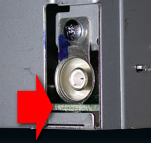
The antenna connector has internal fingers (fig.
3) that grip the center portion of the socket on the rear of
the radio chassis. The main circuit board (fig.
4) can be damaged if you attempt to simply pull the antenna lead
to disconnect it from the radio chassis.
Instead, (1) slightly push the antenna lead toward the radio to relieve
tension on the internal fingers (fig. 5). Then (2) pull back on the
spring-loaded locking ring and remove the connector from the radio.
To install the antenna lead, simply plug it into the socket until it
clicks.
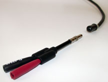
Testing Antenna Lead
Due to the configuration of the antenna lead connector, it is not recommended
that you probe it directly with your multimeter test probes.
Plug the EL-47749 Test Adapter onto the antenna connector (fig.
6). Then plug your multimeter test leads (without probes attached)
into the color matching sockets on the tester. You can now use your
multimeter to test the antenna for continuity and resistance, following
SI procedures.
TIP: Red is the
center conductor and black is the outer shield conductor.
-
Thanks to Nohr Tillman and Jim Hughes |
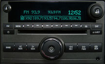
figure 2 |
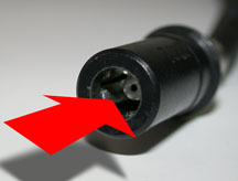
figure 3 |
figure
4
|
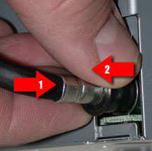
figure 5 |
figure
6 |
return
to Table of Contents |
|
| Mode
Door Actuator |
This information applies to the 2002 Chevrolet TrailBlazer, GMC Envoy
and the Oldsmobile Bravada.
According to bulletin 05-01-38-001A (SI document 1645422), there’s
a new procedure for HVAC Mode Door Actuator replacement. Refer to the
bulletin for details.
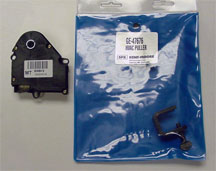
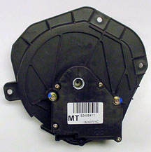
Using Puller GE-47676 permits removing the Mode Door Actuator (fig.
7) from underneath the IP carrier. It’s no longer necessary
to remove the entire IP carrier for access to the Mode Door Cam Assembly.
A Mode Valve Actuator is now available under p/n 89018539. For this
new procedure, do not use Mode Valve Cam Assembly p/n 89018525 (fig.
8).
The service procedure in SI and the labor time have been changed to
reflect use of the new tool.
-
Thanks to Doug Daugherty |
figure
7 |
figure
8 |
| return
to Table of Contents |
|
| E-85
Fuel |
With the escalating cost
of fuel, customers have inquired if they are able to use E-85 fuel in
non E-85 compatible vehicles. Only vehicles designated for use with
E-85 should use E-85 blended fuel.
The only E-85 compatible vehicles produced by General Motors are 2000
- 02 S series pickups equipped with the 2.2L L43 4-cylinder engine and
2002 - 05 full-size pickups and utilities equipped with the 5.3L L59
VIN code Z V8 engine. All other gasoline engines including all 5.3L
V8 with VIN designators other than the letter Z are not E-85 compatible.
E-85 compatibility is designated for vehicles that are certified to
run on a mixture of up to 85% ethanol and 15% gasoline. All other gasoline
engines are designed to run on fuel that contains no more than 10% ethanol.
Use of fuel containing greater than 10% ethanol in non E-85 designated
vehicles can cause driveability issues, Service Engine Soon lights,
and increased fuel system corrosion.
-
Thanks to Jay Dankovich |
| |
| return
to Table of Contents |
|
| Side
Differential Case Bearing Removal |
Camaro
and Firebird
When removing the side differential case bearings, you may discover
that J-22888-20A does not work, because some limited slip differential
cases do not have notches for the jaws of the puller. Use J-34168 to
press the bearing off the case.
-
Thanks to Lance Mossman, Applegate Chevrolet, and Jon Garfield |
| |
| return
to Table of Contents |
|
| TECHAssist
Path |
The April issue of TechLink provided information on when and how to
call Technical Assistance and Techline. Here’s a revised path
for locating training for the Technical Assistance Preparedness Information
Form on the www.gmtraining.com website.
- Menu
- Service Know-How
- Launch TECHAssists
- Technical Service Bulletin Enhancements
- Then scroll to 010089011BT1 --Technical Assistance Preparedness Information
Form.
-
Thanks to Rebecca Farrand |
| |
| |
| |
|
| STS
Tire Pressure Monitoring System Issues |
This
information applies to the 2005 Cadillac STS (fig.
9).
Rear Window Antenna Grid Coaxial Connection
The tire pressure sensor transmissions are received by the remote control
door lock receiver (RCDLR) through the antenna grid in the vehicle’s
rear window. The grid is connected to the RCDLR by a coax cable.
A TPM system malfunction can occur if the connection at the RCDLR is
loose, the center wire in the coax is bent, or the shielding is not
fully secured to the connector end, causing a poor connection.
Always inspect this connection thoroughly before replacing any TPM system
components.
Rear Defroster Grid Micro Arcing
The tire pressure sensors transmit on the FM band at a frequency of
315 MHz and are received by the RCDLR through the antenna grid in the
vehicle’s rear window. Extremely small cracks may develop in the
rear defroster grid that are not visible. When the defroster is turned
on, micro-arcing of electrical current that occurs at the cracks resonates
at a frequency of 315 MHz. Due to the close proximity of the defroster
grid to the antenna grid, this micro-arcing (noise) can interfere with
tire pressure sensor transmissions, causing a TPM system malfunction
to occur.
To verify this condition, use your scan tool to clear any stored TPM
DTCs, test drive the vehicle above 20 mph (32 km/h) for at least 10
minutes, to verify normal system operation. Turn on the rear defroster
and note if the TPM system malfunction correlates with rear defroster
activity. If so, replace the rear window.
Uncommon Tire Pressure Sensor Pressure Sampling Rate
Each sensor takes a tire pressure sample every 30 seconds while in stationary
mode. If the tire pressure increases or decreases by more than 1.6 psi
(11 kPa) from its last transmitted pressure, another pressure sample
will occur immediately to verify the change in pressure. If the pressure
change has indeed occurred, the sensor will transmit in re-measure mode.
This transmission occurs to keep the TPM system updated of any changes
in tire pressure and is an integral part of the pressure increase/decrease
method of the tire pressure sensor learn procedure.
The sensor on the Cadillac STS samples pressure only once every 15 minutes
while in stationary mode. However, the sensor’s “service
period” begins when the sensor’s internal roll switch opens
as vehicle speed decreases, and it lasts for 15 minutes. During this
15 minute service period, the sensors sample pressure once every 30
seconds.
TIP: This is
the only window of opportunity the customer or technician has to perform
the tire pressure sensor learn procedure, using the pressure increase/decrease
method. Otherwise, the verifying horn chirp will not occur.
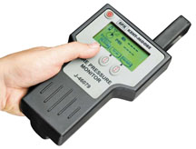
Refer to the “important” information preceding the learn
procedure in SI. It is also important to note that this sensor cannot
be activated using J-41760 tire pressure sensor activating tool (magnet).
The J-46079 TPM diagnostic tool (fig. 10)
must be used to activate this sensor.
-
Thanks to John Spidle |
|

figure
9 |
figure
10
|
| return
to Table of Contents |
|
| Tire
Pressure Monitoring Issues |
Tire
Mounting and Dismounting
This information applies to the 2000--05 Cadillac Deville, Seville,
STS, 2004--05 Cadillac CTS, Escalade, SRX, XLR, 1999--2005 Chevrolet
Corvette, 2004--05 Chevrolet Tahoe, Suburban, 2004--05 GMC Yukon, Yukon
XL.
When dismounting and mounting tires, be careful when breaking the bead
loose from the wheel rim (fig. 11 and 12).
If the tire machine's bead breaking fixture is positioned too close
to the TPM sensor, or pressed down directly on top of it, it may contact
the sensor as the tire bead breaks away from the wheel rim. This can
damage the TPM sensor and require the sensor to be replaced.
Also be careful when transferring the tire bead to the other side of
the wheel rim. As the tire machine rotates and the tire bead is stretched
around the wheel rim, the bead can come in contact with the sensor.
This can also cause sensor damage, requiring replacement. Damage can
be avoided by correctly positioning the wheel and tire in relation to
the mounting/dismounting head.
Tire Dismounting Tips
Refer to SI -- Tire Mounting and Dismounting section for more information.
- Place the sensor's cap and valve on a dry, clean surface after removal.
The cap is aluminum and the valve is nickel-plated to prevent corrosion.
Do not substitute a cap made of any other material.
- When separating the tire bead from the wheel, position the bead breaking
fixture 90° from the valve stem.
- Position the mounting/dismounting head so the tire iron or pry bar
can be inserted slightly clockwise of the sensor body when prying the
tire bead up and over the mounting/dismounting head.
- Using the tire machine, rotate the tire/wheel assembly clockwise when
transferring the tire bead to the outside of the wheel rim.
Tire Mounting
- Position the mounting/dismounting head 180° from the valve stem.
- Position the bead transition area 45° counterclockwise of the
valve stem.
- Using the tire machine, rotate the tire/wheel assembly clockwise when
transferring the tire bead to the inside of the wheel rim.
- Thanks to John Spidle |
figure
11 |
figure
12 |
| return
to Table of Contents |
|
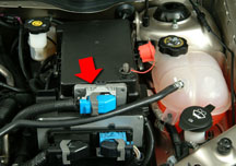
| Transmission
Control Module |
Many electronic control modules have internal circuitry that connects
the outer metal case to internal ground circuits. When +12 volts is
connected to the metal case, damage occurs inside the control module.
This principle applies to all electronic control modules in all GM vehicles.
The following information pertains specifically to the TCM on 2005 Chevrolet
Cobalt and the Saturn ION.
On these vehicles, the Transmission Control Module (TCM) is located
in a plastic bracket mounted on the front of the Underhood Fuse Block/Electrical
Center (fig. 13). The electrical center
contains a remote battery (+) jump-start terminal. The TCM location
is near the jump-start terminal. When the electrical center’s
plastic cover has been removed for diagnostic purposes, the TCM is very
close to the exposed jump-start terminal. If the control module's metal
case accidentally contacts any source of +12 volts (such as the jump-start
terminal), the control module will become nonfunctional. TCM-related
DTCs will set that previously were not stored.
NOTICE: Control
module damage may result when the metal case contacts battery voltage.
DO NOT contact the control module metal case with battery voltage when
servicing a control module, using battery booster cables or charging
the vehicle’s battery.
Field returns of the TCMs from these vehicles often display internal
damage, likely due to accidental contact with the remote positive (+)
battery jump-start terminal with the plastic cover removed. If the TCM
is for any reason not installed into its bracket, and the vehicle battery
is connected, the controller has enough wiring harness length to allow
it to touch the jump-start terminal.
One possible solution is to disconnect the wiring harness connector
from the TCM before performing any work in the area. This will prevent
a shorted out TCM in the even the controller case comes in contact with
B+.
TIP: If the ignition
is turned on with the TCM disconnected, U-code communication DTCs may
set. As always, correct the condition and clear DTCs before releasing
the vehicle.
- Thanks to Steve Bezdek and Jack Woodward |
figure
13 |
|
return
to Table of Contents |
|
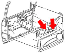
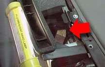
| Front
Door Trim Panel Replacement |
In SI Document 734557, the procedure has been
modified for Front Side Door Trim Panel Replacement on the 2002-05 Envoy,
Rainier, and Trailblazer. The illustration now has callouts showing
the two bolts that must be removed before removing the panel from the
vehicle (fig. 14).
Failure to remove both bolts will result in damage to the trim panel
L-bracket(s). In the event of damage, the L-bracket(s) are not serviced
separately, but are included with the armrest assembly available through
GMSPO.
-
Thanks to Scott Brewster |
figure
14 |
|
return
to Table of Contents |
|
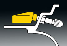
| Weatherstrip
Lubricant |
Krytox®
lubricant is suitable for all weatherstrip and seal applications, including
sunroof seals. It is available in 1 oz. (29 ml) bottles, under the following
GM p/n.
Krytox®
Lubricant |
3634770
US |
10953518
Canada |
TIP:
Use sparingly. The container has a built-in applicator, which allows
for a thin film to be applied.
-
Thanks to Jerry Garfield |
|
|
return
to Table of Contents |
|
| Stanadyne
Diesel Injection Pump Replacement |
This information refers to Special Policy Adjustment
bulletin 00064F, dated September 2004, and applies to 1994-2002 Chevrolet
and GMC trucks with 6.5L diesel engines.
Technician Responsibilities
Before calling the phone number in the bulletin to obtain an exchange
pump, complete the Diesel EFI Diagnostic Worksheet, included in the
bulletin.
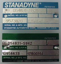
Check the injection pump for tags (fig. 15),
stickers or Stanadyne tags that have been altered, indicating that the
pump has been remanufactured. Reman pumps are not covered under the
special policy.
When requested, all parts including the injection pump must be returned
to the Warranty Parts Center. Failure to return all parts associated
with the repair will result in a debit to the dealer’s parts account.
Removed pumps are not to be sold by the dealer for remanufacturing,
rebuilding or scrap.
TIPS: Take note of the following.
1. You must obtain the exchange pump from GM TAC, by calling the phone
number in the bulletin. Special policy pumps will have a green tag with
part number 17800113 or 17800114. The pump must be installed on the
vehicle listed in the TAC case.
2. You must return all removed parts when requested.
3. The build date on the returned pump must correspond with the last
pump replacement in the warranty history for the vehicle.
4. Pumps obtained from other sources (such as remanufactured, or direct
from Stanadyne) are not covered by this policy or GM part warranty.
-
Thanks to Ian Doran |
figure
15 |
| return
to Table of Contents |
|
| 4T65E
Intermittent Shift Conditions |
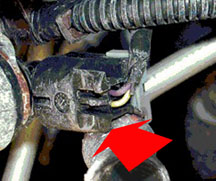
Owners
of some 2004-05 Impalas or Monte Carlos equipped with 4T65E Transmission
(MN3, MN7) may comment that the speedometer intermittently drops or
fluctuates, engine appears to miss, or harsh shift. Diagnosis may not
indicate any codes stored or any abnormal condition.
Inspect the routing of the power steering hose near the transmission
output speed sensor connector. The power steering hose may be contacting
the output speed sensor connector (fig. 16),
causing an interruption or open in the output speed sensor circuit.
Carefully reposition the hose to prevent contact with the output speed
sensor connector.
This information was posted on the Service Information Forums website
by Red Oil Man. Thank you for your contribution.
-
Thanks to Darryl Butler |
figure
16
|
| return
to Table of Contents |
|
| Allison
Transmission Filter |
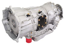
Service Interval Clarification
The first service interval for the Allison transmission is at the pickup
truck’s first maintenance. Change the external spin-on filter
only (fig. 17). Every 50,000 miles (80,000
km) (normal service) or 25,000 miles (40,000 km) (severe service), change
the spin-on filter and fluid. Change the sump filter only during overhaul.
-
Thanks to Bert Druelinger |
figure
17 |
| return
to Table of Contents |
|
| Crankshaft
Balancer Tool |
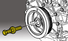
When
installing the crankshaft balancer on the L5 engine in the Colorado/Canyon,
you will discover that the bolt that is part of installer J-41478 is
too long for use on the L5 engine. The tool interferes with the radiator.
An M16 x 2.0 x 220mm bolt is supplied with installer J-41478 (fig.
18). For the L5 procedure, obtain and substitute an M16 x 2.0
threaded rod or bolt, 6.5 inches (165mm) long.
-
Thanks to Lance Mossman, Applegate Chevrolet, Flint Michigan |
figure
18 |
|
return
to Table of Contents |
|
| A/C
Refrigerant Loss |
This
information applies to all GM vehicles.
On the A/C system, the cap with gasket is the primary seal for the high
and low side ports. If the cap gasket is missing, it could cause a small
refrigerant leak and over time lose enough refrigerant to create a customer
comment.
Unless care is taken when the high or low side port cap is removed,
the gasket may not be retained within the cap. It may fall to the floor
or get lost.
When servicing an A/C system or inspecting for a refrigerant leak, verify
that the port cap gasket is present and properly installed.
-
Thanks to Jim Will |
| |
| return
to Table of Contents |
|
| Windshield
Wiper and Washer Issues |
On
some 2002-05 Chevrolet, GMC, Oldsmobile and Buick mid-sized utilities,
the windshield wiper/washer may not shut off, or may have other issues.
The primary concern is that the wiper motor or washer pump will not
turn off. These and other customer concerns have been isolated to the
control module.
Verify the concern and replace the wiper control module only, not the
entire motor assembly.
-
Thanks to Dino Poulos |
| |
| return
to Table of Contents |
|
| HVAC
System Noise |
Owners
of some 2001-05 Chevrolet Venture, Pontiac Montana and Oldsmobile Silhouette
models may report a high pitched whistle or air rushing sound when the
HVAC system is set to full floor and the blower fan is set on high.
The noise may come and go with the fan speed. A possible cause of the
noise is that the defogger vent assembly is not completely seated into
the HVAC plenum.
If all diagnostic procedures have been exhausted and the noise remains,
the cause may be the defogger vent assembly. Follow these steps to correct
the noise.
1. Remove the windshield garnish molding (SI document 508258).
2. Remove the upper trim pad (SI document 630216).
3. Remove the side window defogger outlet ducts (SI document 858993).
4. With both hands, lift up on the center defogger outlet vent until
you hear a small pop or the assembly returns to the seated position.
5. Keep pressure applied to the center defogger outlet vent and follow
it downward until you reach a void between the center defogger outlet
vent and the HVAC plenum.
6. Cut a piece of stiff packing foam into a wedge approximately 2 1/2
inches thick, by 3 inches long, by 2 inches wide (fig.
19).
TIP: The protective
door foam that is shipped with a new vehicle is ideal.
Install the foam wedge between the center defogger outlet vent and the
HVAC plenum on both sides (fig. 20), while
maintaining upward pressure on the defogger outlet vent assembly.
TIP: After steps 4, 5 and 6 have been completed,
test the system to ensure that the complaint is corrected and the center
defogger outlet vent has not become unseated.
7. The wedges will keep the center defogger outlet vent in position
and provide support once the upper trim pad is re-installed.
8. Reverse the first three steps and test the system to ensure that
the concern is repaired.
-
Thanks to Charles Avritt, and Steve Wamback at St. Clair Motors |
figure
19 |
|
figure
20
|
| return
to Table of Contents |
|
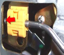
| Sliding
Side Door Operation |
The
sliding door may be hard to open or will not open from the inside door
handle on some 2003-05 Chevrolet Express and GMC Savana vans.
The lock rod may not be adjusted correctly, and can make hard contact
with a gold-colored bracket on the latch assembly. This can make the
sliding door hard to open or cause the lock rod to become disconnected
from the retaining clip on the latch assembly.
The lock rod has a threaded end that snaps into a yellow retaining clip
on the latch assembly (fig. 21). When the
lock rod is installed into the yellow retaining clip, the exposed threads
on the rod should be just about equal on both sides of the retaining
clip. After the lock rod is reattached to the yellow retaining clip,
operate the inside door handle and make sure the lock rod does not make
hard contact with the gold colored bracket on the latch assembly and
that the door opens properly.
-
Thanks to Ron Erman |
| 
figure
21
|
| return
to Table of Contents |
|
| Power
Door Locks Inoperative |
On
the 2005 Chevrolet Equinox, the power door locks may be inoperative
and the 20 amp DR LCK fuse is open.
Inspect the wire harness in both front doors for chafing on the front
of the window regulator. Repair the wire harness as needed and reroute
to prevent any further chafing.
-
Thanks to Ron Erman |
| |
| return
to Table of Contents |
|
| False
DTC B0595 |
For
2004 - 05 Malibu/Malibu Maxx and 2005 G6, a false DTC B0595 is being
set in the BCM. DTC B0595 cannot be erased. Do not replace the BCM.
When perfoming any functions on a BCM, you must use Tech 2 version 25.002
(minimum).
IMPORTANT: This
code has no effect on the vehicle. DO NOT replace any modules for this
code.
-
Thanks to John Mason |
| |
| return
to Table of Contents |
|
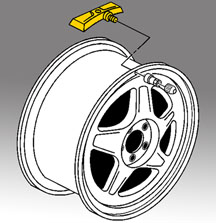
| Plastic
Wheel Nut Caps |
Owners
of some 2005 Chevrolet Silverado and GMC Sierra trucks may comment that
the plastic wheel nut caps are coming loose and/or falling off. This
may occur if the plastic wheel nut caps get hot from excessive brake
use; i.e., going down hill, towing, hauling, etc.
To correct this concern, replace only the plastic nut caps with p/n
9596657. The new caps are made of a more heat-resistant material and
are less susceptible to heat distortion.
The original caps are black. The new nut caps are dark gray. All nut
caps on the vehicle must be replaced (24 nut caps on 6-bolt vehicles
and 32 nut caps on 8-bolt vehicles).
Snap the old (black) nut caps out of the wheel covers, and snap the
new (dark gray) nut caps into place. When installing the wheel covers
on the vehicle, refer to bulletin 03-03-10-002A for the correct procedure
for hand tightening the nut caps.
-
Thanks to Jim Will |
| |
| return
to Table of Contents |
|
| Instrument
Pointer Position |
On
some 2005 Chevrolet Cobalts and Pontiac Pursuits, the instrument panel
gauges may be inoperative. The speedometer pointer will appear frozen
at an offset position of 10° to 340°. In addition, the fuel
and tachometer pointers may appear offset by 10°.
An IPC software issue may cause the described condition, when system
voltage drops as result of a slow drain. This may occur due to an abnormally
high parasitic draw or the ignition switch being left on for long periods.
As system voltage drops, the IPC will reset. Upon exiting reset, the
IPC will move the speedometer pointer by 10°. Each time the IPC
resets, the speedometer pointer moves an additional 10°, up to 340°
total. Once the battery voltage begins to rise, the fuel and tachometer
pointers will move up 10°.
This condition can be corrected by disconnecting the battery or the
cluster fuse. Do not replace the IPC. Service software for the IPC is
expected to be available at the end May 2005.
-
Thanks to John Mason |
| |
| return
to Table of Contents |
|
| Low
or Completely Discharged Battery |
Owners
of some 2004-05 Cadillac XLRs and 2005 Chevrolet Corvettes may comment
that the battery has a low charge or is completely discharged at times.
If a cause can not be located with normal diagnosis, check with the
customer or the sales department to determine if the vehicle is equipped
with an aftermarket security system. These systems use a small transmitter
or GPS locator that is hidden in the vehicle and is usually unknown
to the technician. The transmitter is typically installed in the hot-at-all-times
dome lamp circuit and prevents the Body Control Module (BCM) from entering
the sleep mode.
-
Thanks to Paul Radzwilowicz |
| |
| return
to Table of Contents |
|
| Rear
Cargo Cover Opening |
The
owner’s manual for the 2003 - 05 Chevrolet SSR states that up
to 4 key fobs can be programmed. The 3rd and 4th key fobs programmed
will lock and unlock the doors and the panic button will function correctly.
But the 3rd and 4th key fobs will not open the rear cargo cover.
This is normal operation of the remote keyless entry system. Do not
make any repair attempts for this concern.
-
Thanks to Ron Erman |
| |
| return
to Table of Contents |
|
| Ignition
Key Programming |
When
adding or replacing an ignition key on a Cadillac CTS or SRX, you may
not be able to program the replacement key to the vehicle. This will
result in a no-crank no-start condition or a vehicle that starts and
runs with the security light on when using the new key. This may be
accompanied by a DTC B3976 and/or a DTC B3031.
Some replacement keys have been produced without configuring the transponder
in the key head. If you are attempting to add or replace a key and you
experience this symptom, obtain another replacement key and follow the
published SI procedures to program.
TIP: You may
need to try several replacement keys before you get one that will work.
The manufacturing process is being modified to correct this concern
as soon as possible.
-
Thanks to David Wells |
| |
| return
to Table of Contents |
|
 Car Issues
— Fix It Right the First Time (new issues in bold) Car Issues
— Fix It Right the First Time (new issues in bold) |
Model
Year(s) |
Vehicle
Line(s) --
Condition |
Do
This |
Don’t
Do This |
Reference
Information / Bulletin |
2003-2004 |
CTS
– DTC C0450 or C1241 Set, Service Steering System Message
On |
Replace
only VES solenoid. |
Don’t
replace entire steering gear. |
03-02-36-001A |
2003-2004 |
Cavalier,
Sunfire – Difficult to Adjust HVAC Control Head Mode Dial |
Replace
foam delaminated from mode door, causing bind. |
Don’t
replace HVAC control head, module or cables unless damaged. |
03-01-38-005B |
2002-2003 |
Impala
– Snap/Clunk When Window is Rolled to Full Up Position |
Replace
glass run channel with revised P/N. |
Don’t
replace front door window regulator, door glass or align door
glass for snapping noise when window reaches full up position. |
03-08-64-034 |
2003-2004 |
Cavalier,
Sunfire – Noisy A/C Compressor |
Inspect
for ground-out conditions that can cause A/C compressor noise
complaints. |
Don’t
replace A/C compressor for excessive noise without inspecting
for ground-outs. |
03-01-38-012A |
2005 |
Equinox
LT/LS (AWD Only) – Moan, Bind or Growl Coming from Rear
during Low Speed Parking Lot Turns |
Replace
RDM coupling (clutch pack) with proper sealers. Fill with Versatrak
fluid. |
Don’t
replace complete rear drive module. |
04-04-20-004 |
2005 |
Cobalt/Pursuit
(Built Before January 17, 2005) – Fuel Gauge May Not Go
Completely to Full |
Recalibrate
ECM with updated calibration, version 1.75. |
Don’t
replace fuel module, fuel level sensor assembly or fuel gauge. |
05-08-49-002A |
2002-2005 |
Cars
and Trucks – Multiple Driveability Symptoms/Clogged Fuel
Injectors |
Clean
fuel injectors as described in Bulletin. |
Don’t
replace fuel injectors. |
03-06-04-030A |
2004 |
Grand
Prix – Steering, Suspension or Cradle Click Noise |
Install
new two-piece sleeve and spacer to steering gear mounts. |
Don’t
replace steering gear or cradle. |
03-02-32-048A |
2000-2003 |
Century,
Regal, Lumina, Impala, Monte Carlo, Grand Prix, Intrigue with
3.8L L36 Engine – Coolant Leak |
Replace
upper intake manifold gasket only. |
Don’t
replace upper intake manifold assembly for coolant leak. |
03-06-01-016 |
1999-2004 |
All
Cars and Trucks – Brake Warranty, Service and Procedures |
Issue
One: Refinish brake rotor.
Issue Two: Measure for LRO |
Issue One: Don’t replace brake rotors.
Issue Two: Don’t measure for LRO |
00-05-22-002D |
|
| return
to Table of Contents |
|
|
 Truck
Issues — Fix It Right the First Time
(new issues in bold) Truck
Issues — Fix It Right the First Time
(new issues in bold)
|
Model
Year(s) |
Vehicle
Line(s) --
Condition |
Do
This |
Don’t
Do This |
Reference
Information / Bulletin |
2003-2005 |
Full Size Pickups and Utilities – Rear Seat Audio and/or
Rear HVAC Controls Inoperative |
Replace
RSA. |
Don’t
replace console. |
03-08-44-018B |
2004-2005 |
Midsize and Fullsize Pickups and Utilities – CD Issues |
Load
new software calibration. |
Don’t
exchange or replace radio. |
04-08-44-020A |
2002-2005 |
Tahoe, Suburban, All Yukons, All Escalades, Avalanche, H2 –
Exhaust Pop/Ping Noise |
Replace
heat shield. |
Don’t
replace exhaust system. |
03-06-05-008B |
2003-2005 |
Full
Size Pickups and Utilities – Snap/Popping Noise from Front
of Vehicle |
Use
the procedure found in Service Bulletin. |
Don’t
replace crossmember. |
03-08-61-002D |
2004 |
Tahoe, Suburban, Silverado, Yukon, Yukon XL, Sierra, Escalade,
Escalade EXT, Escalade ESV, H2 – Passenger Door Module and
RKE Inoperative |
Re-flash
passenger door module. |
Don’t
replace passenger door module. |
04-08-52-005 |
2001-2003 |
Fullsize
Pickups – Injector Replacement for High Flow Rates |
Use
Corporate Bulletin
04-06-04-007A for injectors with high fuel return rates. Use Special
Policy 04039 for all 01-02 vehicles. |
Don’t
replace 8 injectors for any complaint other than high fuel return
rates. All other injector failures are fix as failed. |
|
| 2004-2005 |
All
Cars and Trucks – State-of-Charge Upon Delivery of a New Vehicle |
Check
battery state-of-charge per revised PDI procedure using J-42000
or J-42000-EU. |
Don’t
remove and replace battery. |
02-06-03-009A |
| 2002-2004 |
Fullsize
and Midsize Pickups and Utilities – Labor Operation Assignments
for Control Module Reprogramming |
When
submitting claims for reprogramming an electronic module, use correct
labor operation that reflects module being programmed. |
Don’t
use K5364, which is for reprogramming a transmission control module
(TCM), when reprogramming a TCCM. |
02-04-21-006D
02-06-04-057D |
| 2002-2004 |
Chevrolet
Avalanche and Cadillac Escalade EXT – Cargo Covers and Cladding
Faded or Stained |
Thoroughly
clean, dry and treat components with “Armor-dillo.”
|
Don’t
replace cargo covers for this condition. |
04-08-111-001B |
2001-2004 |
Fullsize
Pickups and Utilities – Servicing Wide Load Mirrors (RPO
DPF) |
Replace
individual parts as needed. |
Don’t
replace complete mirror assembly. |
03-08-64-028 |
|
| return
to Table of Contents |
|
|
| Know-How
Broadcasts for July |
| |
 |
| Know-How
Broadcasts for July |
| 10290.07D
Emerging Issues |
July
21, 2005, 9:30 AM and 12:30 PM, Eastern Time |
| New
Model Features and Technology Close-Up seminars |
Stay
tuned! These programs will return soon. Check the Service
Know-How section of the GM Training website (www.gmtraining.com)
for more details. |
| -
Thanks to Tracy Rozman |
|
|
| return
to Table of Contents |
|
