
| Note: Click a picture or illustration in the left column to view a large version in the article. To hide the large version, simply click on it. |


|
||
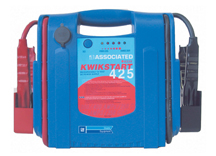
Using Jumper Pack During Programming |
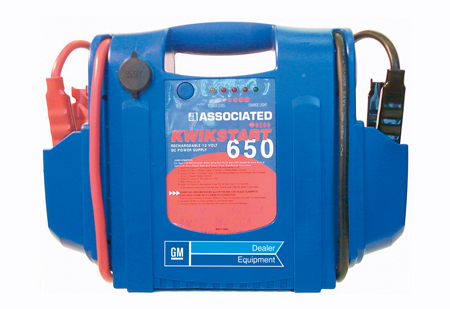
The length of time it takes to program a module has increased dramatically. Some applications can take as much as 30 minutes. This is due to larger calibration files and GMLAN controllers that take longer to program. - 18 amp hour battery - 1000 peak amps - 250 cold cranking amps - 32-inch 4 gauge cables - LEDs for battery state of charge - External charger - Overcharge protection - 400 amp clamps - 18 lbs. Kwikstart Model 6250 (fig. 6) Part No. 110-6250 - Hi-performance 17 amp hour battery - 1650 peak amps - 650 boost amps - 360 cold cranking amps - 32-inch 4 gauge cables - LEDs for battery state of charge - External charger - Overcharge protection - 400 amp clamps - 20 lbs. - Thanks to Mark Stesney and Dave Roland | |


- Thanks to Mark Stesney and Dave Roland
|
||
CH 48106 Suspension Thread Repair Kit Update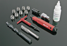 figure 7 |
Here’s the current photo of the CH 48106 Suspension Thread Repair Kit (fig. 7), to replace the one published in the June issue of TechLink.
|
|

|
||
Battery Drain with Retractable Hard Top
|
This information applies to the 2006 Pontiac G6 Convertible (Retractable Hard Top) (fig. 8).
The vehicle should be started and the engine running when demonstrating and cycling the top multiple times. This will prevent a retractable hard top operational issue caused by a low battery state of charge. For further information on this and other top operational issues, refer to the Retractable Top Operational Card shipped with every vehicle and the Know How Course 12442.10V on a CD which was shipped to every Pontiac service department in mid April of 2006. - Thanks to Ray Romeo |
|


|
||
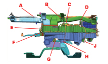
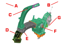
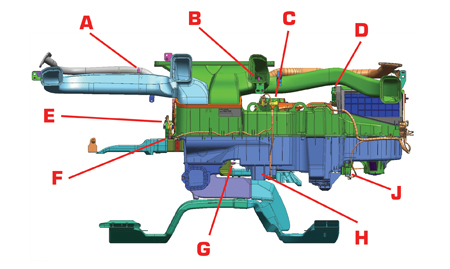
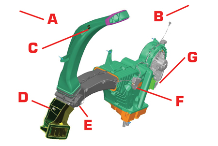
Here’s some supplemental information to use when diagnosing DTC fault codes on the HVAC system in the 2007 full-size utilities. A A |
||
|
||
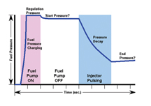
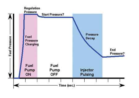
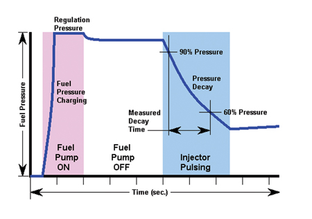
| In a typical fuel injector balance test, the Tech 2 is used to pulse a single injector on a non-running engine (key on) to test the flow of that injector. A fuel pressure gauge connected to the fuel rail indicates the pressure drop resulting from the pulse of each injector. Comparing the pressure drops of all of the injectors on the same vehicle indicates if all injectors are operating properly. This test can be done without vehicle disassembly and serves as a quick troubleshooting step during vehicle repair. Alternate Procedure Required The Tech 2 Fuel Injector Balance Test output control function does not work on some vehicles equipped with the PPEI 3 theft immoblilzer system. Some engines in the following vehices are affected: - 2006-07 Chevrolet Impala/Monte Carlo - 2006-07 Buick Lucerne - 2006-07 Cadillac DTS - 2007 C/K trucks TIP: A complete listing of vehicle/engine combinations is available on the TechLink website, under the Reference Guide tab. After one of these vehicles is in the key-on/engine-off state for 10 seconds, the immobilizer sets a fuel injector disable flag. Once the fuel injectors are disabled, the two Tech 2 output control functions are disabled (fuel injector and starter relay). A fuel injector balance test cannot be completed within 10 seconds. So, an alternative balance test procedure is required. Refer to this heading in SI: Fuel Injector Balance Test With Special Tool. TIP: If the AFIT (see main article) is used on these vehicles, fuel pump operation can be controlled by the tester through the DLC. However, additional jumper harnesses must be installed to the operate the injectors. TIP: The Fuel Pump Output Control on the Tech 2 will still work. There are two ways to tell if the vehicle is affected: 1. Use the list on the TechLink website under Reference Guide. 2. When trying to use the affected Output Controls (if available), the return message “Fuel Enable Not Set For Theft Deterrent” will be displayed on the Tech 2. Effective with TIS Data version 5.0 (May 1, 2006), the Fuel Injector Balance Test is removed from the Tech 2 for the vehicles mentioned above. Refer to Tech 2 version 26.004. The Starter Relay Output Control will also be removed. - Thanks to Mark Stesney and David Schulte |
||
|
||
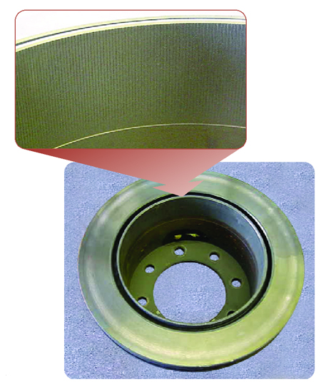
Parking Brake Knurled Surface figure 11 |
On the 2001-06 Chevrolet Silverado and GMC Sierra 3500 with Dual Rear Wheels (RPO R05), there have been questions about a knurled appearance of the parking brake drum-in-hat surface (fig. 11).
The knurling looks like fine machine cut lines across the surface of the drum-in-hat. This knurling can be found on new service replacement rotors, as well as new stock units. The purpose is to improve "green" unburnished park brake performance. As the park brake linings get burnished, the knurling wears off. No repairs should be made. This is a normal condition. - Thanks to Jim Will and Steve Love |
|
|
||
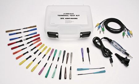
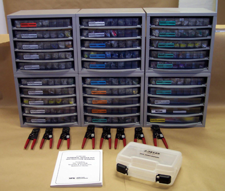
Terminal Test Probe and Terminal Repair Kit Update Information on the Web |
Two extensive and useful reference files have been placed in the Archive section of the TechLink website. To locate them, look at the top of any month’s home page (any language). Locate the Archive tab and click. Then scroll down to locate the files described below. TIP: These files are in PowerPoint format. J-35616 Test Probe Kit History The original J-35616 Test Probe Kit was shipped as an essential tool in 1986 and has been updated several times. This presentation (25 slides) shows every update, from the J-35616 Test Probe Kit’s introduction in 1986 to the current J-35616-C Test Probe Kit (fig. 12). TIP: Proper test probe information is now contained within the Connector End View of almost every connection system in SI. Today’s connection systems use many types of very small terminal sizes which can be damaged if the wrong test probe is used. J-38125 Terminal Repair Kit Update Procedure The original J-38125 Terminal Repair Kit was shipped as an essential tool in 1987 and has been updated numerous times. As time has gone by, the updates have become more complex. It can be very confusing to get the J-38125 Terminal Repair Kit properly organized when left undone for more than two years. IMPORTANT: Your J-38125 Terminal Repair Kit must be updated to the present J-38125-F level before the 2006 update, which is scheduled to ship at the end of 2006. Due to obsolescence, a number of tray cavities will have to be emptied and new terminals will be supplied to fill the vacancies. If your kit is not in order, this will be a very difficult task for you to accomplish. This presentation (82 slides) shows every step in the history of the J-38125 Terminal Repair Kit. But more importantly, it shows you how to organize all of the updates, resulting in the present J-38125-F (fig. 13). SI directs you to a specific tray to find the service terminal you need, and itemizes the specific crimp tool(s), terminal release tool or test probe for each terminal. If the J-38125 Terminal Repair Kit is not organized as this presentation shows, it will take you much longer to locate what you need. TIP: Service terminal information is now contained within the Connector End View of almost every connection system in SI. - Thanks to John Roberts |
|


|
||
Cruise Control and Check Gauges Lights Inoperative |
Vehicle Stability Enhancement System (VSES) is now standard equipment on the Trailblazer and Envoy for 2006-08. This required changes to the base level instrument cluster (without DIC). |
|
|
||
Luggage Carrier Siderails figure 14 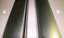 figure 15 |
The luggage carrier siderails on the Chevrolet HHR feature a satin chrome finish (fig. 14). Recently, the manufacturer of these parts began using an environmentally friendly material to produce the finish.
As a result, the satin finish now has a slightly different appearance (fig. 15). This is normal, and no repair or replacement is necessary. A Original finish B Revised finish - Thanks to Dana Rush |
|


|
||
| Using Tech 2 to Diagnose “Service Stability” Light |
This information applies to the 2006 Buick Rainier, Chevrolet TrailBlazer, TrailBlazer EXT, TrailBlazer SS, GMC Envoy, Envoy XL, Envoy Denali and Saab 97x . The Service Stability light is on and DTC C0455 is stored. When the Tech 2 is used, it lacks diagnostics capabilities. This is due to the software within the EBCM/VSES module that allows the Tech 2 to display data. To obtain additional diagnostic data for the Steering Wheel Position Sensor, reprogram the EBCM/VSES with an updated calibration using TIS 2 WEB. Select the calibration titled "New software with diagnostic enhancements for DTC C0455 and changes that eliminate the need to replace the EBCM when the Yaw Rate sensor is replaced." Once the EBCM/VSES has been reprogrammed with the new calibration, the Tech 2 will now be able to access addition stability data related to the C0455 DTC and Steering Wheel Position Sensor. This data will include: - Steering Wheel Position Degrees - Analog Steering Wheel Position Voltage - Digital SWPS Phase A and Digital SWPS Phase B. TIP: To access this additional data in the Tech 2, “build” the vehicle as a 2007 model year in the Tech 2. If the vehicle is “built” as a 2006 model year, the additional Tech 2 data will not be available. Use the Tech 2 path below to obtain this additional Tech 2 data. 2007 / Light Duty Truck, MPV, Incomplete / Select Product Make (Chevrolet, GMC Buick or Saab) / Select Line (S or T) / Select Product Series (Rainier, Trailblazer, Envoy or 97x) / Chassis / Electronic Brake Control Module / Data Display / Select (ABS/TCS/VSES) TIP: Install this calibration only when attempting to diagnosis a steering wheel position/C0455 concern, replacing a yaw rate sensor or when replacing and programming a new EBCM/VSES module. TIP: This calibration offers no performance enhancement to the stability system. It only allows parameters previously missing in the Tech 2 to be viewed and aids in diagnostics, and the ability to recalibrate yaw rate on a 2006 MY vehicle. - Thanks to Dino Poulos |
|
|
||
Navigation Radio Concerns |
Some owners of the 2007 Chevrolet Tahoe, Suburban, GMC Yukon, Yukon XL, Denali, Denali XL with RPO U3U or UVB may experience one or more of the following navigation (U3U) and (UVB) radio concerns: |
|
|
||
Multiple Glow Plug DTCs |
This information applies to 2006 Chevrolet Express, Kodiak, Silverado, GMC Savanna, Sierra, and TopKick |
|
|
||
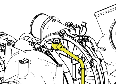
Turbocharger Oil Supply
|
This information applies to 2001-06 Chevrolet, Express, Kodiak, Silverado and 2001-06 GMC Sierra, Topkick. with the 6.6 LB7, LBZ, and LLY engine.
TIP: If the plastic pipe becomes kinked, it will not return to its normal size and shape. The damage may not be obvious when inspected. The braided steel covering will hide the deformity. |
|

|
||
Transmission Fluid Leak |
Some owners of a 2006 Cadillac STS-V or XLR-V, or a Chevrolet Corvette with 6L80 (RPO - MYC) may comment on a transmission fluid leak from the transmission to cooler line connection. The cooler line sealing washer may be missing. This washer is a flat seal that should be located between the cooler lines and the transmission. The sealing washer is available from GMSPO as p/n 15259948. The washer is also included with the transmission oil cooler line set available from GMSPO. - Thanks to Rusty Sampel |
|
|
||
HVAC Control Head |
On the new 2007 full size utilities (Cadillac Escalade, Chevrolet Tahoe and GMC Yukon) with RPO CJ2 or CJ3, a replacement HVAC control head must be programmed using TIS. TIP: When a replacement control head is installed, it may appear to be operational, but if not programmed some functionality will be lost. - Thanks to Jim Will |
|
|
|||||||||||||||||||||||||||||||||||||||||||||
|
|||||||||||||||||||||||||||||||||||||||||||||
|

|
|||||||||||||||||||||||||||||||||||
|
|||||||||||||||||||||||||||||||||||
|
 Truck Issues — Fix It Right the
First Time
Truck Issues — Fix It Right the
First Time
|
|||||||||||||||||||||||||
|
|||||||||||||||||||||||||
|
 Powertrain Issues — Fix It Right the
First Time
Powertrain Issues — Fix It Right the
First Time
|
|||||||||||
Know-How Broadcasts for July
|
|
||||||||||
|
|||||||||||
