| |
|
Note: Clicking
on any picture or illustration will open a larger version of that art.
|
|
Why
the GMLAN? |
GM has been using
on-board computers to control various vehicle functions for over
20 years. Beginning in 1980, a UART system was used to control engine
functions. Later, in 1995, the Class 2 data system permitted numerous
modules on the vehicle to communicate with each other over a common
data line.
With each change, it’s been possible to increase the speed of
data transmission to accommodate an ever-growing number of functions.
Now, starting with 2004, a new GMLAN (Local Area Network) system is
being introduced. It will appear first on the Saturn Ion and 2004 Cadillac
XLR, and will eventually spread to other vehicle lines (fig.
1).
GMLAN is a reliable, cost effective, flexible, and modular way to handle
information sharing between different electronic control units (ECUs)
in the vehicle through the means of a family of serial communication
buses.
While the domestic automakers were developing UART and Class 2, the
European industry was developing a system that operates on the CAN
(Controller Area Network) protocol. With the introduction of GMLAN,
which also uses the CAN protocol, a common architecture now permits
sharing of components from both sides of the ocean.
Some Features of GMLAN
The Class 2 system had only one baud rate -- data was all transmitted
at a single speed.
Using the CAN protocol, GMLAN has two different communication links
with different data baud rates available -- low speed and high speed.
GMLAN Low Speed Bus
This bus will be typically used for operator controlled functions (for
instance, door lock, window motor, etc.) where the system response
time requirements are on the order of 100 - 200 msec.
It uses a single wire (also referred to as single wire CAN or SWCAN).
GMLAN High Speed Bus
The high speed bus is typically used for sharing real-time data. Systems
with these requirements are primarily powertrain and chassis devices
(engine, transmission, brakes). This bus uses two wires, and operates
at 500 kbps.
Because there is a common communications protocol on all buses, it’s
easier to transfer data from one bus to another.
In the Class 2 system, state of health messages pass from module to
module continually. This requires all of the modules to be continually “awake.”
In GMLAN, modules can remain asleep, in a low power state, until asked
to perform. Some ECUs may be communicating while others are in low
power state. Only those ECUs necessary to participate in a common function
are required to be awake. In effect, communication between any collection
(or sub-system) of ECUs can be started or stopped independently of
any other collection.
Present GMLAN Application
The 2004 Cadillac XLR and Saturn Ion use the GMLAN high speed bus for
powertrain applications. Class 2 continues to be used for body and
accessory controllers.
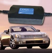
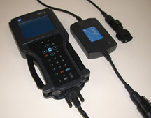
CANdi Module and Tech 2
Vehicles equipped with GMLAN require the use of a CANdi module for
communication with the Tech 2. Class 2 data will pass through the CANdi
module, so it can stay in place regardless of which protocol is being
scanned.
The CANdi module (controller area network diagnostic interface) is
installed in the data cable between the Tech 2 and the DLC (fig.
2).
The fact that GMLAN can operate at different baud rates enhances the
efficiency of vehicle operation and communication. However, the Tech
2 snapshot display frame rate is unchanged.
TIP: Simultaneous to the introduction of the GMLAN is a new diagnostic
process called Functional Diagnosis. Watch for more information on
this in upcoming issues of TechLink.
-
Thanks to John Dobbs |
figure
1 |
|
|
|
|
| |
figure
2 |
return
to Table of Contents
|
|
Attention
Cadillac Dealers
|
In
a few months, the 2004 Cadillac XLR will begin to ship to dealers. This
revolutionary new Cadillac automobile will be the first GM vehicle serviced
by TechLink readers to use the GMLAN (local area network) data communication
system.
TIP: You can
learn more about the GM LAN system in the Know-How broadcasts on March
27 (10270.15D – Tech 2 Functional Diagnostics & GM-LAN).
The Cadillac XLR will use the GMLAN primarily in the powertrain and brake
systems, while the familiar Class 2 data system will be used for body
and accessory controllers.
Your Tech 2 will require an interface called the CANdi module, to communicate
with the GM LAN. CANdi stands for controller area network diagnostic
interface. The CANdi modules and instructions for use will begin arriving
at your Cadillac dealerships shortly.
TIP: It’s
strongly recommended that you perform the Tech 2 functionality test
before you connect the CANdi module.
In preparation for this new Tech 2 use, you must perform a functionality
test on your Tech 2 to be sure the circuits used by the CANdi module
are operating properly.
TIP: An explanation of the functionality test is being sent to Cadillac
dealers along with this March issue of TechLink.
To perform the functionality test, you will need:
- Tech 2
- Tech 2 cable
- ALDL loopback adapter
- VCI
The instructions will guide you to perform the following routines built
into your Tech 2:
- VCI Automated Test
- VCI Dual UART Test
- VCI TPU Option F6 Test
- VCI J1708 Test
These routines verify that a Tech 2 and VCI are working according to
specifications and able to work with the CANdi module. These tests can
also be found on your Tech 2 User Guide CD.
You can perform the functionality test quickly. Do it right away. This
will allow sufficient time if your Tech 2 needs repair.
TIP: The August 2002 issue of TechLink contained a thorough explanation
of how to obtain repair for the Tech 2, whether or not it is in warranty
or under a service contract. Guidance is available at the Techline Customer
Support Center (1.800.828.6860 English or 1.800.502.3222 French).
-
Thanks to Mark Stesney, Matt Singer, Craig Jones and Richard St.
Pierre |
| return
to Table of Contents |
|
| Drive Axle Nut |
When
servicing the drive axle nut on the 1997-2003 Chevy Malibu and 1999-2003
Olds Alero and Pontiac Grand Am, use 10289657 and torque to 235 N.m (173
lb ft). This is a torque-prevailing nut and is silver colored. The old-style
nut is black and has a sheet metal cage around the nut. Using 10289657
will provide a more consistent clamp load on the wheel bearing and should
help prolong bearing life.
TIP: Whenever the axle nut is removed, a new nut should be installed.
-
Thanks to Dave Dickey |
| return
to Table of Contents |
|
|
Know-How Broadcasts
for April |
| |
 |
| Know-How
Broadcasts for April |
| Emerging
Issues |
April
10, 2003 |
9:00
AM, 12:30 PM,
3:30 PM
Eastern Time |
| Technology
Close Up --
2004 Pontiac and Oldsmobile New Model Features |
April
24, 2003 |
9:00
AM, 12:30 PM,
3:30 PM
Eastern Time |
| -
Thanks to Tracy Timmerman |
|
|
| |
|
|
Steering
Wheel Leather Conditions
|
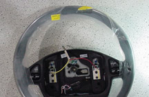
Damaged
leather steering wheels can lead to customer dissatisfaction. Before
replacing a wheel under warranty, look at the accompanying photos.
The following are warranty concerns:
fig. 3 - leather coming apart
fig. 4 - high stitch
fig. 5 - peeling
fig. 6 - loose or pulled stitch
fig. 7 - supplier defect
The following are not warranty concerns:
fig. 8 - scrape
fig. 9 - cut
Avoiding Pre-Delivery Damage
Use care when removing the protective wrap on steering wheels during
Pre-Delivery Inspection. If the protective wrap is pulled or ripped away,
it will scar the steering wheel with permanent scuff marks. If the wrap
is cut away, the steering wheel will likely be cut as well. In an effort
to improve customer satisfaction, follow removal instructions for the
protective wrap by unwrapping the steering wheel.
TIP: To assist in unwrapping the steering wheel, look for a yellow starter
pull-tab (fig. 10) on the plastic wrap.
- Thanks to Monica Pruett and Lorenzo Barone |

figure
8
|

figure
9
|
|
figure
10 |
return
to Table of Contents |
| |
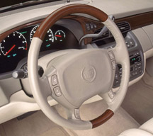
| Minor
Scratches to Wood Steering Wheels |
This
information applies to all 2000-03 Cadillac vehicles with wood steering
wheels (fig. 11) and will be covered in detail in upcoming bulletin
03-02-35-002.
Some customers may comment that the wood section of their steering wheel
has minor scratches in the clear coat.
Here are the highlights.
Remove the steering wheel, following procedures in the Steering Wheel
and Column subsection of the Service Manual.
Wash the wood section of the wheel with wax and grease remover, then
mask off the non-wood area of the steering wheel.
Sand with 400 grit sand paper, followed by 600 grit.
IMPORTANT: Do not sand through the clearcoat.
Wash the wood section of the wheel with wax and grease remover.
Clear coat the steering wheel. Refer to the 2003 GM Approved Refinish
Materials Booklet, GM 4901 M-D-2003 (English) or GM 4901 M-D-F2003 (French).
Then install the steering wheel, following procedures in the Steering
Wheel and Column subsection of the Service Manual.
-
Thanks to Brian Dotterer
|
figure
11
|
| |
| return
to Table of Contents |
|
| Power
Outlets |
Beginning
with the 2003 model year, a new service manual subsection was created
called Power Outlets. This new subsection includes all the needed
information on the 115 volt accessory power receptacle used in the
Pontiac Vibe.
Beginning with the 2004 model year, Power Outlets will also include schematics
and replacement procedures for cigar lighters and 12 volt accessory power
outlets (receptacles) for all vehicles.
-
Thanks to Eric Baur |
| return
to Table of Contents |
|
| Two
Theft Deterrent Subsections in Service Manuals -- Reminder |
Some
2002 and 2003 service manuals will contain two Theft Deterrent subsections.
Use ONLY the subsection titled Theft Deterrent for diagnosing the
theft deterrent system.
The subsection titled Theft Deterrent - Immobilizer is for vehicles sold
outside the United States and Canada. DO NOT use it for vehicles operated
within the United States or Canada.
-
Thanks to Dale Tripp |
| |
| return
to Table of Contents |
|
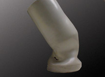
Intermediate Shaft Boot |
Owners of some 2003 Buick
Centurys and Regals may comment about increased steering effort when
turning right or left. This condition may be caused by possible interference
between the intermediate shaft and intermediate shaft boot (fig.
12).
A quick determination can be made whether the intermediate shaft and
intermediate shaft boot are in contact. Raise the vehicle. With the ignition
on and the engine off, have an assistant turn the steering wheel from
right to left. Grasp the intermediate shaft boot. While the steering
wheel is being rotated, there should be no contact felt between the intermediate
shaft boot and the intermediate shaft. If contact is felt, replace and
properly position the intermediate shaft boot.
TIP: An additional symptom of this condition may be the appearance
of a white powdery substance on the "top hat" portion of
the steering gear, which has been analyzed as material from the intermediate
shaft
boot.
-
Thanks to Wayne Zigler |
figure
12 |
| return
to Table of Contents |
|
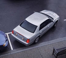
| Rear
Park Assist Update |
Numerous GM cars, trucks and vans now offer the Rear Parking Assist
(RPA) system (TechLink, August 2000). The RPA helps the driver know
how close the rear bumper is to an object when backing up (fig.
13).
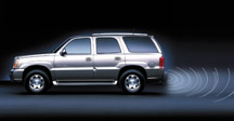
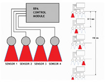
RPA uses an array of four object sensors in the rear bumper which transmit
ultrasonic sounds. By comparing signals that bounce back to the object
sensors, the RPA control module can calculate how far away an object
is. The normal range extends about 5 feet (1.52 m) behind the vehicle,
from 10 inches (25.4 cm) above ground level to the top of the bumper
(fig. 14).
RPA operates when the shift lever is moved to Reverse and the vehicle
is moving below 3 mph (5 kph) (higher speeds interfere with the ultrasonic
signal).
Telltale Light Operation
A display of telltale lamps, two amber and one red, is located above
the rear window and is visible in the rear view mirror.
Initially, all three lamps come on momentarily to indicate that the system
is working.
TIP: If something is wrong with the system, the red lamp flashes and
the system disables.
When the vehicle backs up and RPA detects an object 5 feet (1.52 m) behind
the vehicle, the first amber light comes on and a chime sounds. At 40
inches (101.6 cm), the second amber light comes on and the chime sounds
again. At 20 inches (50.8 cm) the red light comes on and the chime sounds
continuously.
The telltale lamps are also used for diagnosis, explained later.
Special Operating Conditions
The lamp may flash red if the ultrasonic sensors are not kept clean.
Be sure to remove mud, dirt, ice or slush. A particle of dirt lodged
between the sensor membrane and body can result in a false alert.
Some conditions outside the vehicle may cause the red lamp to flash.
These include vibrations such as from a jackhammer or the operation of
air brakes on a very large truck.
TIP: In the diagnostic stall, the operation of an air powered tool nearby
can cause interference, also.
All of these flashing lamp conditions are normal and do not require repair.
Brief Explanation of Sensor Operation
A later section outlines approved diagnostic procedures. Some technicians
choose to attempt diagnostic steps not included in the SI charts, such
as using a digital volt-ohmmeter to test the wiring at the object sensors.
The data obtained from this test is meaningless.
The following explanation will help you understand the RPA system, and
is intended to point out why a voltage check at the sensors will not
work.
The four sensors “fire” individually, in a continuous cycle
that repeats every 150 milliseconds. This means that each sensor has
only 37.5 milliseconds to arm, fire and receive the returning signal.
The resulting voltage changes in the sensor circuits occur far too
fast to be discerned by a volt-ohmmeter.
To make the point, here’s a breakdown of the cycle for one sensor.
Remember, all of this occurs about 27 times per second.
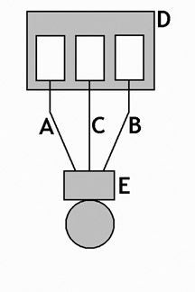
Refer to figure 15. Note that there are three wires at the sensor:
A 8 volt supply line
B low reference line
C sensor signal line
The other components shown include:
D RPA module
E RPA sensor
There is voltage between the supply and low lines at all times. At the
beginning of the cycle (fig. 16), the module pulls the signal line low,
telling the sensor that its turn is coming. The sensor responds by pulling
the sensor line low at its end. This tells the module to start its timer.
At the same time, the sensor transmits its ultrasonic beam, using the
8 v and low lines for power.
During the transmission time, the sensor line is neutral. As soon as
the sensor receives a bounceback signal, it again pulls the sensor line
low, telling the module to stop the timer. From the amount of time recorded,
the module can calculate the distance to the object.
Diagnosis
The RPA control module is capable of detecting faults and storing diagnostic
trouble codes. To put the control module into the code display mode,
ground the diagnostic connector at the control module, turn the ignition
on, and shift to Reverse within 5 seconds. The lamps then display codes
using various light patterns. Refer to the service manual to interpret
the codes and make the repairs listed.
TIP: The flashing
lamp codes are used to indicate failures of various components in the
system. There is no flashing lamp code to indicate
module failure. The system simply doesn’t work in this case.
To erase diagnostic codes, be sure the diagnostic connector is not grounded.
Drive the vehicle forward at least 15 mph (24 kph), then stop and turn
the ignition off to clear codes. Codes may also be cleared by turning
the ignition on, shifting to Reverse within 5 seconds, and turning the
ignition off.
TIP: On some vehicles, vans in particular, the geometry of the rear bumper
affects the operation of the RPA. Be sure the bumper cover is not distorted
or sagging toward the ground, which could cause the RPA signals to detect
the ground as an object. This is not a fault of the system, but a fault
of the bumper position.
TIP: When diagnosing the system in a service stall, be sure to remove
all objects from behind the vehicle. A tool on the floor, a stack of
tires nearby, or other objects may cause false alerts.
Refinishing
TIP: The
object sensors are sensitive to paint thickness. If the paint is
too thick, the red diagnostic lamp will remain on. When painting
a
replacement sensor, refer to basecoat/clearcoat paint procedures.
Be sure the paint thickness does not exceed 6 mils (0.006-inch,
0.15 mm),
as determined by a non-ferrous paint thickness gauge.
- Thanks to Paul Ogu and Kevin Fondaw |
 figure
13
figure
13
|
figure
14 |
 figure
15
figure
15
|
figure
16 |
|
return
to Table of Contents |
|
| Auxiliary
Gasoline Generators Will Not Run |
Owners
of some 2002 Chevrolet Express or GMC Savana Vans may comment that
their vehicle's auxiliary gasoline generator (installed by a dealer
or an upfitter) will not run when the vehicle is not running.
Vehicles built with reverse flow check valve (RFCV) fuel sending units
will not allow fuel through the sending unit check valve into the auxiliary
generator with the vehicle shut off.
Replace the vehicle's fuel sending unit with a non-RFCV fuel sending
unit. Refer to Fuel Sender Assembly Replacement (SI Document ID 693842).
Observe SI cautions when working on a fuel system.
A bulletin is expected.
- Thanks to Dan Oden
| 25314353 |
Fuel Sending Unit, Non RFCV, 31 Gallon, California Emissions |
| 25314352 |
Fuel Sending Unit, Non RFCV, 31 Gallon, Federal Emissions |
| 25326140 |
Fuel Sending Unit, Non RFCV, 35 Gallon, California Emissions |
| 25326141 |
Fuel Sending Unit, Non RFCV, 35 Gallon, Federal Emissions |
|
|
|
|
|
| return
to Table of Contents |
|
| Accelerator
Pedal Buzz and Vibration |
This
condition affects some 2003 Silverado, Suburban, Tahoe, Avalanche,
Sierra, Yukon, Denali, Escalade, and EXT vehicles.
Owners may experience a buzz noise which can be heard and felt, from
the accelerator pedal area on the first acceleration after starting the
vehicle. It will occur only the first time the vehicle reaches approximately
10 mph (16 kph) after start-up. It will not occur again until the key
is cycled off then on. Based on the driving habits of the owner, the
condition may occur at approximately the same time as the 1-2 shift of
the automatic transmission.
This noise is caused by the Supplemental Brake Assist (SBA) performing
a self-test. The SBA, which is mounted to the brake vacuum booster canister,
is new for 2003 and provides vacuum for the brake booster in case of
low vacuum or vacuum loss.
This is a normal condition and no repair attempts should be made.
The SBA is used only on vehicles equipped with vacuum brake boosters
and is not used on vehicles equipped with Hydra-Boost brake systems.
- Thanks to GM Technical Assistance |
|
|
| return
to Table of Contents |
|
| Engine
Noise and Vibration |
Owners
of some 2002 Chevrolet TrailBlazers, GMC Envoys and Oldsmobile Bravadas
with the 4.2L LL8 engine may experience noise and vibration between
800 - 900 rpm. They may comment about engine buzz noise, and vibration
felt at the accelerator pedal, steering wheel, and center console.
Verify that the intake pre-plenum is securely mounted. Press down on
the plastic intake pre-plenum. If the vibration is eliminated, replace
the intake pre-plenum with part number 15176239.
- Thanks
to GM Technical Assistance
|
| |
|
return
to Table of Contents |
|
| MAP
Sensors |
The
MAP sensor is an important part of the modern engine control system.
When asked, “What does MAP mean?” most technicians could
correctly answer, “Manifold Absolute Pressure.”
The next question, though, would stump most.
What is absolute pressure?
In absolute measurement, the zero point (where the measuring device indicates
zero) is an absolute zero pressure. That means no pressure, or in other
words, a 100% vacuum.
The pressure gauges I have indicate zero when no pressure is being measured.
Isn't this absolute zero?
No. Most pressure or vacuum gauges indicate zero pressure when not connected,
or when there is no pressure or vacuum being measured. However, there
actually is pressure -- the atmospheric pressure that surrounds the earth.
You mean barometric pressure?
Yes, even though your pressure or vacuum gauge may indicate zero, the
atmospheric or barometric pressure is always present. Conventional gauges
always measure gauge pressure.
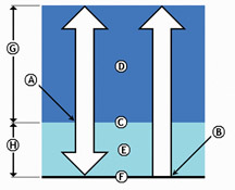
What is gauge pressure?
Gauge pressure has its zero point at the current barometric pressure
(fig. 17). Everything above barometric pressure is called pressure and
everything below barometric pressure is called vacuum.
A - Gauge Pressure Zero indicated here
B - Absolute Pressure Zero indicated here
C - Current barometric pressure
D - Atmospheric Pressure
E - Vacuum
F - Perfect Vacuum
G - Operating Range of Standard Pressure Gauge
H - Operating Range of Standard Vacuum Gauge
Conventional pressure or vacuum gauges are constructed to measure gauge
pressure to keep the cost affordable.
An absolute pressure gauge is bulky and expensive. Laboratory-grade devices
that measure absolute pressure cost over $1000.
Tell me about atmospheric, or barometric, pressure.
The two terms are interchangeable. Atmospheric pressure at sea level
on a standard day is approximately 14.7 pounds per square inch (psi),
or 29.9 inches of mercury (HG), or 101 kilopascals (kPa), or 1 Bar.
These various standards differ only in the units of measure used to express
them.
Does atmospheric pressure always stay the same?
No. Two factors can make the atmospheric pressure vary. First, at an
altitude above sea level the atmospheric pressure goes down, because
the density of the air goes down.
Second, weather or climate can change the atmospheric pressure -- high
pressure or low pressure days. This is why the standard sea level atmospheric
pressure is listed as being on a standard day.
How do my conventional pressure or vacuum gauges act at various altitudes?
They react the same at high altitude as at sea level, which is exactly
the point we are getting to.
Conventional pressure gauges have no way to compensate for different
altitudes or weather changes. They will indicate zero either at sea level
or at the top of a mountain. However, the atmospheric pressure is certainly
different at these two extremes.
Why is this atmospheric pressure measurement so important?
The air in the atmosphere contains oxygen. An engine burns a mixture
of oxygen and fuel. For an engine to burn efficiently, it has to have
just the right mixture of fuel and oxygen.
To determine the correct air/fuel mixture and the correct ignition timing,
the PCM must know the atmospheric (BARO) pressure. If the PCM is to compensate
for changes in altitude or weather, it must have an input signal that
reflects these changes in atmospheric pressure.
The Manifold Absolute Pressure sensor does this?
Yes. And, on engines that do not have a Mass Air Flow (MAF) sensor, the
MAP sensor signal is also used by the PCM to calculate engine load --
how hard the engine is working. This is called the speed-density method
of calculating engine load for engines without MAF sensors. It is because
of this engine load calculation for speed-density engines that the accuracy
of the MAP sensor signal is so critical.
On OBD-II engines, the MAP sensor signal is also used for EGR diagnosis.
What are the normal ranges of the sensor's output voltage?
The most common MAP sensor generates an output voltage between 0 and
5 volts, depending on the pressure being measured. It must be able to
measure atmospheric pressure at the lowest elevations, which in some
areas is slightly below sea level. The standard atmospheric pressure
at sea level is about 101 kPa. In the Death Valley, Utah, which is below
sea level, the atmospheric pressure can be higher than 101 kPa. At the
top of Pikes Peak mountain in Colorado, which is more than 14,000 (4,267
m) feet above sea level, the baro pressure is less than 65 kPa. So, the
MAP sensor must have a measurement range of 105 kPa to about 15 kPa.
How does the MAP sensor measure pressure UP from absolute zero?
Imagine two glass jars glued together at the open ends, with a flexible
membrane sealed between them. Drill a hole into the bottom of each jar,
and glue a tube into each hole. Now, connect a powerful vacuum pump to
one of the tubes.
When the vacuum pump removes ALL the atmospheric pressure from the jar,
seal the tube, trapping the vacuum in the jar. The flexible membrane
will be pushed in towards the vacuum chamber jar by the atmospheric pressure
in the open jar.
The vacuum jar has absolutely no pressure in it, so it becomes the absolute
zero reference point.
Any pressure on the atmospheric side will push the flexible membrane
in, but higher pressure will push it in further.
Remember, high pressure in this case equals atmospheric pressure, about
101 kPa at sea level.
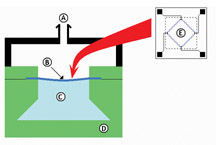
Now, attach a hose from the intake manifold of your engine to the open
jar. Devise an electrical circuit to measure how far the membrane flexes,
and you have the basic idea of how a MAP sensor works (fig.
18).
A - Hose fitting to manifold
B - Thin silicon diaphragm
C - Reference pressure chamber (Absolute vacuum, zero pressure)
D - Pyrex glass
E - Sensing resistors on silicon diaphragm
When would I ever measure a reading as low as 15 kPa?
The sensor is called a manifold absolute pressure sensor because its
sensing element is connected to the intake manifold, either through a
hose or a direct mount. When the engine is not running, the pressure
inside the intake manifold is equal to atmospheric pressure, and the
PCM will use this "engine not running" MAP signal as the BARO
reading.
A running engine acts like a large vacuum pump. When the throttle is
nearly shut, the pressure in the intake manifold is very low -- as low
as 15 kPa at a high-speed, closed-throttle deceleration. As the throttle
is opened, the pressure inside the intake manifold increases because
the atmospheric pressure outside the intake manifold is rushing in, limited
only by the engine's throttle blade opening.
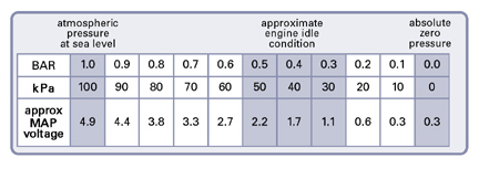
The accompanying chart shows that low manifold pressure (engine idling)
equals low MAP output voltage, and high pressure (engine at WOT or not
running at all) equals high MAP output voltage.
What is the function of the three wires leading to the MAP sensor?
One of the wires provides a precise 5 volt power supply from the
PCM. Another wire provides the ground circuit, grounded only through
the PCM.
The third is the signal wire, carrying the signal voltage generated
by the MAP sensor to the PCM.
-
Thanks to Jack Woodward |
figure
17 |
| |
figure
18
|
| |
| |
|
|
|
New Tech
2 Programming Function |
A
new Service Programming function is being added to the Tech 2. It
will be released on CD 3, which will reach the field in March.
TIP: This new Tech 2 function will apply first to the 2004 Pontiac Grand
Prix and will spread across all model lines in 2004. Pontiac dealers
can expect to see their first 2004 Grand Prix models this month.
Occasionally, when you’re using your Tech 2 to diagnose a control
module on a vehicle, you may conclude that it’s necessary to reprogram
that module with the latest calibrations. At this point, you’re
already in the Diagnostic Menu of the Tech 2.
In the present Tech 2 version, you have to return to the Main Menu to
select Service Programming System (SPS) Request Info to enable the Tech
2 to obtain the necessary information from the vehicle.
There are two disadvantages to this. First, you have to do a lot of button
pushing to get to where you want to be. And second, when the command
is given, simultaneously every module on the vehicle that can be reprogrammed
is requested to respond.
Revised Method in the New Software
In the new software, there’s a way to go directly from diagnostics
to programming. While you’re in the Diagnostic Menu, simply press
Special Functions.
TIP: Some modules don’t support Special Functions. For these, you
will continue to use the existing method.
In the Special Functions menu, one of the choices is SPS Request Info.
Choose this and you will be ready to request the necessary information
from the vehicle.
TIP: When you use this new method, only the module you’re working
on is commanded to respond, which speeds up the process.
Downloading from TIS Terminal
With your Tech 2 hooked up to the TIS terminal, you must make the proper
module selection from the menu.
TIP: This selection must match the module on the vehicle you downloaded
identification from. Improper module selection will cause a Programming
Failed message at the vehicle when trying to program it.
Programming Event
Once the appropriate new data has been downloaded from the TIS terminal
into your Tech 2, the actual programming event proceeds as it always
has. That is, you will go to the Main Menu and select Service Programming
System.
Final Tip
For the foreseeable future, the old Information Request method will remain
on the Tech 2 for those who want to continue to use it. You will now
have two methods to choose from.
-
Thanks to Glen Crifasi |
| |
| |
| return
to Table of Contents |
|
| New
TIS Feature |
TIS
is an evolving product supporting more modules and more vehicles, not
just in North America but globally. It now supports China, Daewoo,
Holden, and Toyota, for instance.
To accommodate additional vehicles, an Options Menu has been added to
Remote Programming (fig. 19).
In the Options menu, you will now have to make additional selections
(make, model year, option content).
These selections must be made before selecting the module to be programmed.
You can then view the available calibrations for the specified vehicle
and complete the download.
The look of some graphics will change, but functions remain the same.
This change will be effective in the 3.2 release in mid-March.
-
Thanks to Mark Stesney
|
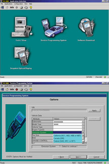
figure
19
|
| return
to Table of Contents |
|
| Crew
Cab Wind Noise |
Owners
of some S-10 Crew Cab pickups with ZR5 sports package may comment about
a wind noise. This may be caused by the roof rack.
Check the position of the forward cross-bar of the roof rack. It should
be slightly rearward of the B-pillar (fig. 20). This helps alleviate
the sound pressure at the A-pillar, where it’s most sensitive to
driver and passenger.
All vehicles leave the assembly plant with the cross-bar in this position,
but it may be relocated by the owner when the roof rack is used.
-
Thanks to Dan Oden |
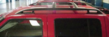
figure
20
|
| return
to Table of Contents |
|
| Bulletins – February,
2003
This review
of service bulletins released through mid-February lists the bulletin
number, superseded bulletin number (if applicable), subject and models. |
00
– General Information
02-00-89-019; Labor Operation Times and Straight Time Pilot Updates;
2003 Cadillac CTS
01 – HVAC
01-01-39-004A; replaces 01-01-39-004; A/C Not Cold Enough, A/C Blows
Warm Air with Vehicle at Extended Idle (Install Auxiliary Electric
Coolant Fan); 2002-03 Cadillac Escalade, Chevrolet and GMC Pickup and
Utility with 6.0L Engine (VINs U, N -- RPOs LQ4, LQ9)
03 – Suspension
00-03-10-003D; replaces 00-03-10-003C; GM Tire New Vehicle Warranty
Program; 1996-2003 Passenger Cars and Light Duty Trucks, 2003 Hummer
H2
02-03-10-008; Recommended Wheel Nut/Bolt Torque Specifications; 2003
Passenger Cars and LD Trucks, Hummer H1, H2
03-03-10-001; Tire Slowly Goes Flat and/or Excessive Wheel Vibration
(Replace Wheels with New Heavy Duty Rim Version); 1999-2003 Chevrolet
and GMC 1500 Series Pickup Models with 6-Bolt, 16 x 6.5 Full Face Steel
Wheel (Base and RPO PY2)
04 – Driveline Axle
02-04-19-001; Revised Differential Carrier Assembly Replacement; 2002
Chevrolet TrailBlazer, GMC Envoy, Oldsmobile Bravada
03-04-95-001; Revised Wheel Drive Shaft Outer Joint and Seal Replacement
and Wheel Drive Shaft Inner Joint and Seal Replacement Procedures;
2001-03 Chevrolet Corvette
05 – Brakes
02-05-23-005A; replaces 02-05-23-005; Required Use of Silicone Lubricant
on Brake Caliper Slider Pins; 2003 Chevrolet and GMC C4500/C5500 Series
02-05-25-007; Parts Restriction Program for Vehicle Stability Enhancement
System (Stabilitrak); 2003 Cadillac Escalade, Chevrolet and GMC Utility
03-05-25-001; Thumping Noise/Feel in Brake Pedal (Replace Electronic
Brake Control Module); 2003 Chevrolet and GMC 1500/2500 Series HD Cargo
Van with GVW of 8600 -- 11000 lbs
06 – Engine/Propulsion System
02-06-01-039; Whine or Growl Noise from Engine After Cold Start --
Normal Characteristic; 2003 Chevrolet Impala with Police Package (RPOs
9C1, 9C3)
02-06-04-059; Engine Runs Rough, SES Light On, DTCs P0300 or P0335
Set (Shim Crankshaft Sensor); 2002-03 Chevrolet and GMC Pickups, Vans
and Utilities with 4.3L V6 Engine (VINs W, X -- RPOs L35, LU3)
02-06-05-005A; replaces 02-06-05-005; Exhaust/Muffler Heat Shield Rattle,
Popping Noise Under Vehicle (Install Heat Shield Retaining Straps on
Muffler); 2002-03 Cadillac Escalade, Chevrolet and GMC Pickup and Utility,
Hummer H2 with 5.3L or 6.0L Gas Engine (VINs T, N -- RPOs LM7, LQ9)
Except 1500 Series
03-06-04-001; Revised DTC P0122; 1996-97 Chevrolet and GMC C/K pickups,
S-trucks, Vans, and Utilities with 4.3L, 5.0L, 5.7L, or 7.4L Engine
(VINs W, X, M, R, K, N, J -- RPOs L35, LF6, L30, L31, LO5, L19, L29)
03-06-04-002; Vehicle No-Start in Extreme Cold (Install Injection Pump
Heater); 1999-2003 Chevrolet and GMC W-Series MD Tilt Cab with 4HE1-T
Diesel Engine
03-06-04-003; Use of New Special Tool J-46363 -- Fuel Line Disconnect
Tool for Fuel Filter Removal/Installation Procedure; 2002-03 Chevrolet
and GMC Pickup and Utility with 5.3L Flexible Fuel Engine (VIN Z --
RPO L59)
03-06-04-004; Revised DTC 0341; 1996 Buick Century, Regal, Skylark,
Chevrolet Beretta, Corsica, Lumina, Monte Carlo, Oldsmobile Achieva,
Ciera, Cutlass Supreme, Pontiac Grand Am, Grand Prix with 3.1L Engine
(VIN M -- RPO L82)
03-06-04-005; Revised DTC P0230; 1998-99 Chevrolet Camaro, Pontiac
Firebird with 3.8L Engine (VIN K -- RPO L36)
03-06-04-006; Revised Electronic Ignition (EI) System Diagnosis; 2001-02
Chevrolet Impala, Monte Carlo with 3.8L Engine (VIN K -- RPO L36)
03-06-04-007; Revised DTC P0443; 2001-02 Oldsmobile Aurora, Intrigue
with 3.5L Engine (VIN H -- RPO LX5)
03-06-04-008; Exhaust Gas Recirculating (EGR) Valve Cleaning Prior
to Potential Replacement; 1999-2000 Chevrolet Tracker with 2.0L Engine
(VIN C -- RPO L34)
03-06-04-009; Engine Deceleration Hesitation, Loss of Power on Vehicles
with Police Package (Reprogram PCM); 2001-02 Chevrolet Impala with
3.8L Engine (VIN K -- RPO L36) and Police Package (RPOs 9C1 or 9C3)
04-06-05-002; SES Light On, Reduced Vehicle Performance, Acceleration
and Top Speed (Replace Catalytic Converter and Brake Vacuum Booster
Hose with Thermo Protection); 2001-02 Chevrolet Impala with 3.8L V6
Engine (VIN K -- RPO L36) and RPOs 9C6 Taxi Cab, 9C1 Police Car and/or
9C3 SEO Vehicle Police Car, Limited Content
07 – Transmission/Transaxle
02-07-30-012A; replaces 02-07-30-012; Hydra-matic 5L40-E Serviceable
Components and Labor Operations; 2003 Cadillac CTS with 2.6L or 3.2L
Engine (VINs M, N -- RPOs LY9, LA3) and 5L40-e (RPO M82) Transmission
08 – Body and Accessories
02-08-43-005; New Windshield Wipe Motor Assembly; 2003 Chevrolet
Cavalier, Oldsmobile Alero, Pontiac Grand Am, Sunfire
02-08-43-006; Revised Wiper Inoperative-Rear Diagnostic; 2002 Chevrolet
TrailBlazer, GMC Envoy, Oldsmobile Bravada
02-08-49-011; Console Air Deflectors Inoperative, Broken or Missing,
Door Latch Broken (Replace Appropriate Component); 2002-03 Buick
Rendezvous
02-08-67-009; Sunroof Jams When Closing (Install Guides); 2002-03
Cadillac Escalade, Chevrolet and GMC Utilities
03-08-44-001; XM Radio Labor Operation Codes; Specified 2003 Vehicles
03-08-47-001; Cigar Lighter and Accessory Power Outlets Time Out
After 10 Minutes (Relocate Fuse); 2000-03 Cadillac DeVille, Seville,
CTS
03-08-48-001; Windshield Stress Cracks (Replace Windshield); 2002
Chevrolet Tracker
03-08-49-001; Rattle in Floor Console Cupholder Door (Add Felt Washer);
2003 Cadillac Escalade, GMC Sierra, Yukon with Luxury Package (RPO
Y91) and Custom Front Floor Compartment (RPO D07)
03-08-50-001; Second Row Seat Center Armrest Panel Warping (Replace
Panel); 2003 Cadillac Escalade, Chevrolet Avalanche, Chevrolet and
GMC Pickup Crew Cab and Utility
03-08-52-001; Remote Keyless Entry (RKE) System Inoperative (Reprogram
Passenger Door Module); 2003 Cadillac Escalade, Chevrolet and GMC
Utilities, Hummer H2
03-08-64-001; Sliding Side Door Effort (Install Retainer); 2002-03
Chevrolet Astro, GMC Safari
03-08-66-001; Deck Lid Not Flush With Left Hand Quarter Panel (Install
Struts, Replace Right Deck Lid Hinge); 2003 Chevrolet Corvette Convertible
and Z06)
03-08-110-001; Rear Storage Compartment Tray Hinge Support Link Breaks
(Replace Link); 2002-03 Chevrolet Venture, Oldsmobile Silhouette,
Pontiac Montana
|
| return
to Table of Contents |
|
|
| |
|
|
|
| |
|
|
|
| |
|
|
|
|