| |
|
Note: Clicking
on any picture or illustration will open a larger version of that art.
|
|
Fuel
Tank System |
Corvette
and Cadillac XLR
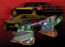
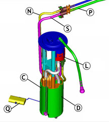
Partway through model year 2003, a new fuel tank system was introduced
on the Corvette (fig. 1). This system continues
with slight differences in the 2004 Corvette and Cadillac XLR.
TIP: For 2003
Corvettes only, this system was designated by RPO code FFS. However,
this name has been unofficially applied to all vehicles with the new
system.
Advantages and Features
The new fuel tank system was designed to accommodate future LEV 2 emission
requirements. This was accomplished by moving as many components and
fuel lines as possible inside the fuel tanks, to minimize hydrocarbon
emissions. A flexible metal crossover hose assembly replaces the former
rubber one, because the permeable rubber allowed a small amount of hydrocarbon
to pass through.
The redesign also includes more isolation and noise control for the
electric fuel pump, which now has greater flow capacity to supply higher
output engines.
Component Layout
TIP: Use the
reference letters to identify and locate the various components.
A Left side tank
B Right side tank
C Fuel sensor reservoir
D Turbine fuel pump
E Venturi pump
F Fuel fill hose
G Secondary fuel pressure regulator
H Siphon jet pump
J FLVV
K Crossover hose
L Filter
M Fuel feed pipe to engine
N Fuel feed pipe to RH tank
P Fuel return pipe to LH tank
Q Left fuel level sensor
R Right fuel level sensor
S Anti-siphon hole
T Fuel pump speed control module
U EVAP canister
V Primary fuel pressure regulator
W Check valve
TIP: On the XLR
only, a speed control module (T) slows the fuel pump when the engine
is idling, to further control pump noise.
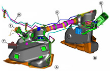
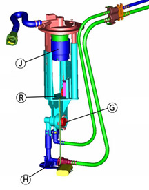
Two fuel tanks are used, and they’re joined by crossover plumbing
(fig. 2 and fig. 3). The left side (driver
side) tank (A) is considered the primary, and the right
side (passenger side) is secondary (B).
Each tank contains a sensor module, which includes a float and resistor
card.
On the left side, the sender module includes a reservoir (C),
containing the turbine fuel pump (D). There’s
also a primary fuel pressure regulator (V) and a venturi
pump (E). The left tank is also supplied by the fuel
fill hose (F), and has a rollover vent valve.
On the right side, the sender module contains a secondary fuel pressure
regulator (G) and a siphon jet pump (H).
There is also a fill limiting vent valve (FLVV) (J).
Operation
When the fuel tanks are filled, fuel first fills the left tank. As the
fuel rises to the level of the crossover (K), fuel
flows into the right tank. As fuel occupies the interconnected tanks,
air is forced to vent from the tanks, through the FLVV in the right
tank. When both tanks are full, the FLVV float in the right tank closes,
preventing fuel from entering the vent system. This also causes fuel
to back up in the fill hose, causing the gas pump nozzle to shut off.
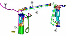
When the engine is running (fig. 4), the
turbine fuel pump (D) in the left tank pressurizes
the fuel feed pipe (M). The entire fuel supply system, from the pump
to the injectors, is pressurized. The turbine pump creates more pressure
and more fuel flow than the engine needs. Excess pressure and excess
fuel is allowed to bleed back into the left tank by the primary fuel
pressure regulator (V) within the tank.
TIP: The pressure
regulator is in the fuel tank, not on the fuel rail on the engine. This
type of fuel system is called returnless, or demand. This means that
excess fuel is diverted before it leaves the tank, instead of passing
through the fuel rail before being diverted. The result is that hot
fuel is not constantly returning from the engine compartment, so the
fuel in the tank stays cooler, improving evaporative emissions.
The majority of the pressurized fuel is directed through the filter
(L) and on to the fuel feed pipe (M) to the engine,
where it is injected into the cylinders for combustion.
Some of the pressurized fuel is directed through a feed pipe (N) inside
the crossover hose, to a siphon jet pump in the right tank. The jet
pump relies on the venturi effect to use pressurized fuel to draw additional
fuel from the tank. The combined fuel then flows from the right tank
to the left tank, through a return pipe (P) inside
the crossover hose. The jet pump is able to move enough fuel to ensure
that all of the fuel in the right tank is consumed before the level
in the left tank begins to drop.
TIP:
The return tube in the left tank has an anti-siphon hole (S), so the
fuel in the left tank does not siphon back to the right side when the
vehicle is shut down.
Some of the pressurized fuel is directed to a venturi pump in the left
tank. This pump uses fuel flow to siphon fuel from the main tank into
the reservoir, to keep the turbine pump supplied with fuel at all times.
As the left tank fuel level drops, the venturi pump scavenges all of
the remaining fuel into the reservoir, regardless of the vehicle’s
attitude.
When the engine is shut off and the turbine pump stops, a reverse flow
check valve (W) maintains pressure in the system to
ensure rapid pressure buildup during the next startup cycle.
Operation of Fuel Level Gauge
When the fuel system is operating as designed, starting with both tanks
full, the left tank will remain full until the right tank is depleted.
Then the left tank will be emptied.
Each fuel tank has its own sensor (Q and R
in the illustrations). Modules are shown in figure
5 (LH module) and figure 6 (RH module).
The PCM supplies a reference of 5 volts to the two sensors. Each sensor
operates across a range from full (2.5 volts) to empty (0.7 volts).
The PCM monitors the fuel level sensor voltages and calculates how much
fuel is in the two tanks. The readout of the IP fuel level gauge is
a result of this calculation.
TIP: The fuel
level sensors can be monitored with a Tech 2.
Several “zones” are used to describe various combinations
of fuel levels in the two tanks.
Zone 1 -- The LH voltage is above its full threshold
(typically calibrated to 2.4 volts) and the RH voltage is above its
empty threshold (typically calibrated to 0.8 volts). Fuel volume = capacity
of LH tank + volume in RH tank. This is the normal condition, before
the fuel in the RH tank is completely consumed.
Zone 2 -- The LH voltage is above full threshold and
RH is below empty threshold. This is also known as the deadband zone.
Fuel volume = volume in LH tank + deadband volume - fuel used since
entering zone. This is also a normal condition. It occurs because the
actual amount of fuel in the tanks cannot be precisely indicated by
the positions of the floats. That is, when the float reaches the top
of its travel, it’s possible that the tank will hold additional
fuel, which does not cause the float to move higher. Similarly, when
the float reaches the bottom of its range, there may still be some fuel
in the tank, and the float does not move any lower as the remaining
fuel is consumed. So, the fuel in the bottom of the RH tank and the
top of the LH tank will be consumed without either float moving. This
is the “deadband.”
Zone 4 -- The LH voltage is below full threshold value.
Fuel volume = volume in LH tank. This condition occurs just after the
zone 2 “deadband” is passed. All of the fuel is gone from
the RH tank, and the LH sensor has begun to move down. The amount of
fuel in the LH tank is all that remains.
Zone 5 -- The LH voltage is below its full threshold
and the RH voltage is above its empty threshold. Fuel volume = volume
in LH tank = volume in RH tank. This is a condition that should not
occur in normal operation, because the RH tank should be consumed before
the float in the LH tank begins to drop. If the fuel system is in zone
5 for a certain amount of time, a DTC (1431, 2066 or 2636) will set,
and the fuel volume will be reported as zero by the fuel gauge.
A zone 5 condition could occur if the jet pump in the RH tank becomes
clogged, preventing fuel from being siphoned from the RH tank. In this
case, only fuel in the LH tank is available.
TIP: Service
kits are available for each sensor, including:
- float
- wire arm
- wiper
- card
- card holder
Diagnostic Situations
The following situations may apply to the Corvette (C5), the Cadillac
(XLR) or both, as noted.
Jet Pump Clog (C5, XLR) -- If the jet pump in the RH
tank becomes clogged, fuel will not transfer to the LH tank. When this
occurs, the vehicle eventually runs out of fuel, even though there is
actually some in the RH tank. When the DTC (1431, 2066 or 2636) sets,
the fuel gauge drops to empty and the customer perceives an “erratic
gauge.” One cause of this condition was a piece of plastic left
in the jet pump during the manufacturing process. This has been remedied.
Fill Quality (C5) -- A customer may comment that the
fuel nozzle shuts off prematurely, before the fuel tanks are full. The
maximum flow rate for gas station pumps is supposed to be 10 gallons
(37.9 L) per minute, and the fuel system is designed to accommodate
this rate.
TIP: In reality,
pump nozzles vary considerably in configuration, flow and shutoff sensitivity.
Ask the customer if the condition occurs at all stations, all the time,
or at just one pump. This could point to a pump nozzle problem, not
a vehicle problem.
Be sure the rubber hose to the canister vent solenoid (next to the transmission)
is not restricted and that the vent solenoid is not stuck closed. Both
can cause fuel to back up in the tanks and filler hose, causing the
pump nozzle to shut off.
TIP:
A replacement filler hose between the fill pipe and the LH fuel
tank is available with a smaller inside diameter for C5. Although this
sounds like it would make the condition worse, the smaller diameter
allows less swirling, creating smoother fuel flow. A bulletin is pending.
Regulator Not Seated, Clip Loose (C5, XLR) -- If the
clip retaining either regulator is not fully engaged, the fuel system
will lose pressure and the vehicle may stall. This condition was remedied
in production.
If the secondary regulator (right tank) is not seated, it could result
in fuel not transferring from the right tank. It could also cause long
crank times, because residual pressure is lost in the fuel feed pipe
to the engine when the engine is shut down.
TIP: With the
engine off, a pressure gauge connected at the fuel rail should indicate
52 psi (359 kPa). If pressure drops rapidly, the regulator may be unseated.
Open Fuel Level Sensor Circuit (C5, XLR) -- If an open
occurs in a fuel level sensor circuit, the fuel gauge will drop to empty
and a DTC will set. This could be caused by an unseated electrical terminal.
Check the wiring circuits before replacing fuel system components. Another
cause, which has been corrected, was the sensor wiper fingers not in
contact with the resistor card, over the full sweep of the sensor.
TIP: The DTC specifies which
sensor circuit has the issue. Only that sensor should be replaced.
LH Module Opening Too Small (C5, XLR) -- In some LH tanks,
the module opening was undersized, making it difficult or impossible
to remove the module. This has been corrected in production.
TIP: In any case,
be careful of the sensor float wire when removing the module, to avoid
damage.
Service Procedure Notes
TIP: Refer to IDL course 10260.22D, Technology
Close-Up from October 2002, for additional information.
TIP: Always consult SI before
performing a service procedure. The following are highlights and tips
only.
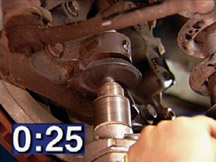
Removing Fuel Tanks -- The crossover hose must be disconnected
from a fuel tank which is being removed. The crossover is located above
the driveline and exhaust system, making removal appear difficult. Both
SI and the Labor Time Guide allow lowering the driveline and exhaust
for access. See Driveline Support Assembly Replacement in SI.
Once you have performed this procedure, you will gain enough knowledge
of the components that you may be able to do the procedure in the future
without lowering the driveline.
Crossover Hose -- The crossover hose is made of corrugated
flexible stainless steel. It is retained to each fuel tank by a collar
and a CPA (Connector Position Assurance). With the CPA aside, the collar
can be turned by hand. It may be necessary to wiggle the crossover while
pulling it straight out -- DO NOT TWIST.
The fuel feed and fuel return pipes for the transfer pump are inside
the crossover, and are sealed with O-rings. The crossover is sealed
to each tank with two O-rings. When installing the crossover, lube the
O-rings and O-ring sealing surfaces with 1051717 rubber lubricant. Then
align the pipes and push the crossover into place. DO NOT FORCE.
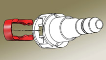
TIP:
There is a T-shaped alignment feature (fig.
7) between the feed pipes which can be assembled only one way.
With the crossover in place, turn the collar. If the crossover and pipes
are properly aligned and assembled, the collar can be turned with two
fingers. Then snap the CPA into place.
Fuel Tank Module Replacement -- It is necessary to
remove the fuel tank from the vehicle before removing the module. Procedures
are different for LH and RH tanks.
TIP: Fuel Sensor
Lock Ring Tool J-39765A is required.
When the lock ring is loosened, the module will spring upward, because
it is spring-loaded to ensure it is bottom-referenced and to resist
noise.
Follow the SI procedure exactly. It is necessary to disconnect and reconnect
numerous fuel lines. The only access is through the module and crossover
openings.
TIP: When the module is installed,
be sure to check the empty and full readings of the fuel level sensor.
Your DMM should read 40 ohms with the tank in vehicle orientation (simulating
empty) and 250 ohms with the tank upside down (simulating full).
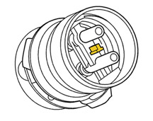
Fuel Line Quick Connectors
Fuel lines use quick connectors, described in the February 2004 TechLink.
See page 6 for details.
TIP: To release, push on the retainer using
hand pressure only. Do not attempt to remove it.
If the retainer becomes broken, it can be replaced
(fig. 8) using the following part number.
5/16-inch
(0.3125) |
3/8-
inch (0.375) |
5/8-inch
(0.625) |
External
vapor and internal liquid lines |
Internal
liquid lines |
FLVV
connector to the evap canister |
214992748 |
22717568 |
21992746 |
Bulletin
02-06-04-010A -- This bulletin applies only to vehicles with
the previous fuel system, which could be affected by fuel with an aggressive
sulfur content. It does not apply to any XLR or 2003-04 Corvette with
the FFS fuel system. DO NOT use this bulletin to justify reprogramming
the PCM or replacing fuel sensors/modules in vehicles with the FFS fuel
system.
TIP: In the new
system, DO NOT reprogram the PCM unless specifically told to do so by
a diagnostic procedure.
-
Thanks to Dave Libby, Terry Stone and Dave Peacy |
|
figure
1 |
|
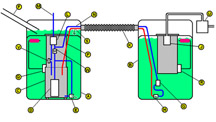
figure 2 |
 figure
3
figure
3 |
figure
4
|
|
figure
5
|
figure
6 |
|
figure
7
|
figure
8 |
| return
to Table of Contents |
|
|
| Snapshot
During Cranking |
Here’s a useful service tip. You can use your Vehicle Data Recorder
J-42598 (either the original or the revised version) to take snapshots
during engine cranking.
The VDR will capture data from the time the ignition is turned on, through
the crank cycle, until the engine starts (or doesn’t start).
The data collected can be useful in diagnosing an intermittent or hard-start
condition.
To set up for this kind of snapshot, select the appropriate pre-built
engine data list. Be sure the data you think you need is in the list
you choose.
TIP: You can
set the trigger point anywhere you wish, but the best result is probably
to place the trigger point in the middle of the data collected.
Unless a diagnostic code sets as a result of the no-start, it will be
necessary for you to trigger the VDR manually.
-
Thanks to Mark Stesney and Mike Banar |
|
|
|
|
New Video Presentation of Recall Bulletin |
Product
Recall Bulletin 03044 has just been released, to explain a steering
knuckle modification on 2003 Chevrolet Astro and GMC Safari 2WD M-vans.
This bulletin is being supplemented with a narrated video, available
on SI (fig. 9).
This is a new method of delivering recall information. It allows you
to actually see the repair being performed, using the special tools
called for in the bulletin.
If this presentation method proves popular, it may be used in the future
to portray unusual or new service procedures.
How to Access the Video
Go to the SI home page in normal fashion: http://service.gm.com.
In Canada, access the video via GM InfoNET.
Click on Service Information.
Go to the bottom of the topic list and locate the link for 2003
Astro/Safari 2WD Steering Knuckle Modification Video -- Recall 03044.
TIP: The next
step is important.
RIGHT CLICK on the link. Then click on OPEN IN NEW WINDOW. This opens
the large-size video viewer. (If you left click, the viewer will open
at reduced size.)
TIP: On some
browsers, it may be necessary to drag the viewer to full size, using
the arrow in the lower right corner of the viewer.
Once the video has downloaded, click the PLAY arrow to view the video.
It runs about 4 minutes. Use the slider to control the volume of the
narrative sound track.
You may rewind the video and view it additional times. When you are
finished, click on the X in the upper right to close the video viewer.
TIP: Dealers
without high-speed internet connections may order a CD copy of this
repair procedure video at their own expense from the GM DealerWorld
DWD online store or by calling 1.866.700.0001.
- Thanks to Gary Smits |
|
figure
9 |
return to Table of Contents |
|
| New
Style Catalytic Converter |
The
2004 Chevrolet Malibu with the 3.5L V-6 (RPO LX9) is equipped with a
new style of catalytic converter, technically known as the close-coupled
catalytic converter. Each engine exhaust manifold bolts directly to
a catalytic converter, providing quick catalyst warm-up, resulting in
lower tail pipe emissions earlier in the vehicle operating cycle.
If a catastrophic engine failure were to occur (such as broken intake/exhaust
valve or piston), debris may be deposited in the converter through engine
exhaust ports. If a new engine were installed and debris is present,
the replacement engine may fail due to the debris being reintroduced
into the combustion chambers during negative exhaust back pressure events.
TIP: When servicing
an LX9 for a catastrophic engine failure, perform an inspection of the
catalytic converters for debris (on the exhaust manifold attachment
end).
TIP: In addition,
in cases where severe engine overheating is suspected of causing the
engine failure, inspect each catalytic converter ceramic brick for signs
of heat damage (melting or cracking of the ceramic brick). If heat damage
is noted, the converter should be replaced.
-
Thanks to John Fletcher |
| |
| return
to Table of Contents |
|
| 20-Inch
Wheels and Tires |
Additional
Information
IMPORTANT: The VCI fee and the labor to install the calibration
cannot be charged as a warranty claim. Dealer claims will be reviewed
and any dealer warranty claim for the installation of 20-inch wheels
and tires will be debited to the dealer.
The January 2004 issue of TechLink announced a new 20-inch wheel and
tire accessory package that dealers can offer to certain truck customers.
The article mentioned the need for obtaining a VCI number for reprogramming
the PCM as a part of the installation procedure. Techline charges a
fee for issuing the VCI number.
Installation of these accessory wheels, tires and additional parts and
related procedures are entirely at customer expense. |
| return
to Table of Contents |
|
| GM
Oil Life System, One More Time |
Attention Service Managers: If
your Service Consultants are already reading TechLink, great.
If not, now is the time to include them when handing out our
monthly newsletter. TechLink is a great source of information
that can be used when discussing vehicle issues with your customers.
The accompanying Oil Life System article is just one of many
with helpful information.
Mark
Stesney, Publisher
|
Where do you stand
on the following issues?
1. Do you want to continue to build customer loyalty and grow your business?
2. Do you want to show your customers you truly have their best interests
at heart?
3. Do you want to help improve the environment?
4. Would you like to quit being a part of the throw-away generation?
GM’s development of the Oil Life System and its relationship to
the new Simplified Maintenance Schedule have a direct bearing on how
well you can answer YES to all of these questions.
How the Oil Life System Works
We’ve explained the GM Oil Life System (GMOLS) in detail before
(March 2000, May 2003) so this is going to be brief.
GMOLS is a computer-based algorithm that assesses engine combustion
events, temperature, vehicle use, and other parameters to determine
optimum oil change intervals. Oil changes are now called for when actually
needed, instead of depending on generic time or mileage interval tables.
Mild highway driving in a mild climate can yield change intervals of
7,000 miles (11,000 km) or more, and as high as 12,000 miles (19,000
km) for some vehicles. Short trip driving in cold weather may reduce
intervals to 3,000 miles (5,000 km) or less. Most people driving a combination
of city and highway will likely see intervals of about 6,000 miles (10,000
km).
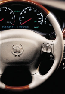
When GMOLS determines that an oil and filter change is needed, the driver
is notified by a Change Oil message on the instrument panel (fig.
10). Oil should be changed within 600 miles (1000 km).
TIP:
The Oil Life System must be manually reset when the oil is changed.
How the Oil Life System is Related to Maintenance
The previously complicated, traditional normal/severe maintenance schedules
required about 25 pages of explanation in the owner’s manual.
The new simplified maintenance schedules can be explained in about 3
pages (see TechLink May 2003 for a summary).
All routine maintenance is grouped into one of two schedules, Maintenance
I and Maintenance II. These services should be performed alternately,
each time the GMOLS message is displayed.
Benefits of GM Oil Life System and Simplified Maintenance
Benefits for the customer -- GMOLS takes the guesswork out of when oil
changes are needed; the owner doesn’t have to keep track of anything.
With maintenance intervals now aligned with oil changes, the customer
can conveniently have both done during one service visit.
Benefits for the dealer -- Because of the typically
extended oil change intervals, the customer may come back less frequently.
But when they do come back, it’s for more services. The inspection
and service points of both Maintenance I and Maintenance II are thorough,
and are intended to keep the vehicle in good working order. They also
give the technician the opportunity to locate, identify and recommend
other needed services.
Benefits for the environment -- With GMOLS now installed
on upwards of 20 million vehicles, if it’s used as intended, it
can save almost 100 million gallons of oil in 5 years. And remember
that every quart of oil poured into an engine eventually has to be drained
out and properly disposed of.
What’s Next?
In the next few months, GM is going to saturate owners with information
about the GMOLS. Radio interviews, TV talk shows, magazines, newspapers,
the internet and dealership kits will all be used to promote a proper
understanding of GMOLS and its benefits, and to promote its proper use.
GMOLS was also promoted at the National Auto Dealers Association (NADA)
convention in January of this year.
How Can You Prepare?
Because of GM’s media efforts, owners are going to become familiar
with GMOLS. It’ll be a good idea for you to get yourself up to
speed as well.
IDL Courses -- Three courses have been designed to
promote GMOLS and customer retention.
- Understanding the GM Oil Life System (PPS03.P1D) explains
the reasons and benefits behind the GMOLS and provides suggestions for
explaining it to customers.
- The GM Oil Life Maintenance Schedule -- Keeping the Cutomer at
the Dealership (PPS03.P4D) covers the benefits of the new maintenance
schedules and explains how to use them to benefit customer-pay business.
- Building Trust and Long-Term Customer Retention (PPS03.P6D) explains
how to earn and build customers’ trust and how to retain them.
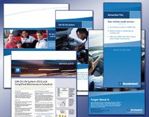
Literature and Materials -- GMSPO is making Oil Life System
promotional material available through several sources. (fig.
11) You can download service reminder letters and maintenance
schedules at gmpartscoop.com. GMSPO-approved
vendors have a wide selection of new service reminders including a message
about GMOLS. A kit including poster, consumer brochures, and counter
display is available from gm-dealerworld.com.
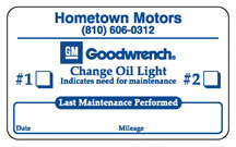
Maintenance Reminder Stickers -- Traditional stickers
provided a place to write the date and/or mileage for the next oil change.
To encourage use of the Oil Life System, a new maintenance reminder
sticker (fig. 12) says the Change Oil Light
indicates a need for maintenance. It provides a place to check off whether
the next service should include Maintenance I or Maintenance II, plus
the date and mileage of the last maintenance performed.
TechLink Articles -- See the March 2000 and May 2003
issues of TechLink for summary information. If you cannot locate these
back issues, they’re still available on the internet at http://service.gm.com.
TIP: TechLink
also published procedures for resetting Oil Life Systems in January/February
2002, and May/June 2003.
-
Thanks to Chuck Burns |
figure
10 |
figure
11 |
figure
12
|
| return
to Table of Contents |
|
| Cooling
System Seal Tabs |
What’s
made of ground-up ginger root, almond shells and binder? And causes
confusion in auto service departments?
Some people call them coolant pellets, but the proper name is Cooling
System Seal Tabs. And we hope to clear up some misunderstandings about
them.
How They Work
Seal tabs are dissolved in the engine coolant and the resulting fibres
circulate through the cooling system. At a microscopic level, the tabs
break down into irregular, long, thin fibres. When a small leak or seepage
occurs, the coolant carries the fibres into the opening, where they
cluster up and jam together. (Think of logs and branches in a beaver
dam.) This mechanism is very effective at stopping leaks. Any fibres
that make it to the surface will crust over and enhance the seal.
This sealing method is useful only for small-scale leaks and seepage,
and tends to work best in conditions where the surrounding parts aren’t
moving. The seals tend to break down in areas between metals that are
expanding and contracting with temperature changes, for instance.
A Secondary Benefit
The traditional green-colored coolant, used until DEXCOOL® was introduced
in 1996, contained silicates, which deposit on cooling system surfaces.
The tiny fibres from the seal tabs acted as scouring pads, removing
silicate deposits from the water pump seal faces, which contributed
to longer water pump seal life.
Side Effects of Seal Tabs
In addition to the benefits of sealing small leaks and scrubbing silicates
from water pump seals, seal tabs also have some side effects.
After awhile, a brown, dirty-looking stain may form on translucent coolant
bottles. Residue may form on the backside of the radiator cap. And deposits
that resemble rust may be found in the cooling system.
These are not problems, in the sense that they cause no physical harm.
But their appearance can be alarming, especially on a new vehicle. Both
customers and well-intentioned technicians can be misled by these deposits.
Another side effect comes from overuse. When seal tabs are used in the
prescribed amounts, they will not cause restrictions or plugging in
an otherwise properly operating cooling system.
But, if a little is good, a lot must be better. Wrong!! Overuse can
lead to plugging, especially in the relatively small tubes used in heater
cores.
Some History
There was a time when seal tabs were installed in every new vehicle,
at the factory, to account for the inevitable small leaks that occur
in castings, joints, and so on. By the mid ‘90s, manufacturing
and machining techniques had improved to the point where the seal tabs
were no longer needed on a universal basis.
With the introduction of long-life coolant, silicate deposits were no
longer a concern, so the scrubbing action from the seal tab fibres was
no longer needed.
TIP: GM plants,
as well as other manufacturers, still occasionally use seal tabs to
address specific concerns.
Today’s Recommendations
In short, GM no longer endorses universal use of seal tabs. Procedures
in SI have been specifically written to discourage their use in most
cases.
When a condition appears in which seal tabs may be beneficial, a specific
bulletin is released, describing their proper use. One such bulletin
is Customer Satisfaction Program 03034, dated 7/7/03. This applies to
specific 3.8L engines only, and is in effect until July 31, 2005.
TIP: After performing
the procedure in the bulletin, be sure to install a recall identification
label to the vehicle to indicate that the seal tabs have been installed.
TIP: If seal
tabs were installed in a vehicle at the factory, it’s OK that
the proper amount of tabs be installed if the coolant must be drained
and replaced.
What’s a Recommended Dose?
TIP: Use this
information only when instructed to do so by bulletin or SI procedure.
The proper number of Cooling System Seal Tabs depends on the capacity
of the vehicle’s cooling system. Use between 1 and 1 1/2 grams
of tabs per liter of cooling system capacity.
TIP: Cooling System Seal
Tabs are packaged in two sizes.
12378254 |
Small
tabs (4 grams each) |
5
tabs per package |
3634621 |
Large
tabs (10 grams each) |
6
tabs per package |
-
Thanks to Greg Cockerill and Gary McAdam |
|
|
return
to Table of Contents |
|
| Service
Tips for Chevrolet Aveo (and Optra and Epica) |
The
service manuals (SI) for the Chevrolet Aveo, Optra, and Epica incorporate
content for more than 80 countries. Add-on titles are based upon region.
Three regions are used to differentiate content:
- North America
- Europe
- Neither North America nor Europe.
Too many countries are involved to list each country that uses a procedure.
If no add-on title is listed with the procedure or diagnostic title,
the procedure is common to all regions.
The Tech 2 software for the Chevrolet Aveo, Optra, and Epica incorporates
content for more than 80 countries. Technicians will need to select
the emissions package that is used in their country. The four options
are:
- ECE 83
- Euro II
- Euro III
- ULEV
Technicians in the US, Canada, and any other country that uses US emissions
(for example Guam) need to select ULEV.
- Thanks to John Bowman |
| |
| return
to Table of Contents |
|
| TAC
Corner |
Be
Prepared
Before calling the Technical Assistance Center, use the TAC form and
diagnostic worksheet to organize your call. The forms are tools to help
you provide quality service that will keep your customers coming back
to your dealership.
TIP: You can
locate the forms in the P&P Manual, Section 5.3.1.
The TAC Form is designed to help you make sure you have the essential
information you need in isolating a diagnostic path. When you take the
time to organize the information on the TAC form (TAIF), as well as
the diagnostic worksheet (DWS-01) which is filled out by the customer,
it may help get to the issue without generating a call to TAC. If a
call is necessary, using the form will reduce the time TAC needs to
assist you.
New Product Action Center
Another important topic is the Technical Assistance New Product Launch
Action Center. As most of you are already aware, TAC has initiated action
centers for each of the new products launched this past year.
The purpose of the Action Center is to quickly identify, communicate
and resolve product concerns on new vehicle launches. Special teams
receive dealer calls and take action as new vehicles arrive at GM dealerships.
This information is quickly relayed to the assembly plant, engineering
and Brand Quality to insure quick resolution of the customer's issue
and to help prevent additional occurrences.
The Action Centers are joint activities, which include the SPO Contact
Centers (TAC, SPAC, and Partech), Brand Quality, Assembly Plant Quality
Teams, Plant Training, Raytheon, Regional Service Engineers and the
CDC.
Each time a call comes in to the Action Center, the TAC call prompts
will guide the caller to an expert on the new product.
1. A TAC case is created, or updated.
2. Case closings on these cases are very important, as the information
is used by the Launch Team several ways:
- allows for real time changes to be made at the plant.
- reduces the number of quality related issues from reaching the customer.
There is a goal of 24-hour resolution/escalation. The Action Center,
as you can see, is tied directly to our Technical Assistance Center,
as well as to the assembly plants.
-
Thanks to Technical Assistance |
|
|
|
return
to Table of Contents |
|
| Leaking
or Broken Transmission Case |
The 4L60E/4L65E automatic transmission may experience a leak, inoperative/slipping
2nd, 3rd, and 4th gears or no movement (no forward or reverse) due to
excess fluid loss. This condition normally occurs at low mileage, usually
under 1,000 miles (1,600 km), and diagnosis may show a cracked or broken
case at the 2/4 servo bore.
This condition may be caused by a 2/4 servo cover retaining ring that
was not fully seated during transmission assembly. Pressure from the
servo cover against the partially seated retaining ring can cause the
case to crack or break.
If the fluid level drops due to the leak, it is likely that the 3/4
clutches will be damaged. This condition can usually be repaired by
replacing the case and any damaged clutches.
-
Thanks to Mark Gordon |
| |
|
return
to Table of Contents |
|
| XLR
Window Initialization |
This
information applies to the XLR if:
- the battery is disconnected
- the battery is in a run-down condition and requires a charge (such
as in an extended storage period)
- the window module has been disconnected.
If the window module loses battery power, the window module needs to
be initialized. The top will not operate and the window express-up and
express-down will not function unless the window module knows the window
position.
To initialize a window module, the top must be up, and the door for
the window being initialized must be fully closed. Turn the ignition
ON, engine OFF. (See February 2004 TechLink for this procedure.) Run
the window to the UP position and hold the switch continuously for a
minimum of 0.5 second. Run the window to the DOWN position and hold
the switch continuously for a minimum of 0.5 second. Once the window
module learns the window's positions, the top will operate properly.
TIP: If the door
window express-up or express-down function does not operate, use the
window initialization process before attempting any other repairs.
- Thanks to Jim Mikolaizik and Jason Macco |
| |
|
return
to Table of Contents |
|
| Allison
LCT1000 Transmission Conditions |
Chevrolet
and GMC C/K2500HD and C/K3500 trucks equipped with the Allison LCT1000
transmission may experience a condition in which the PRNDL display is
inoperative and the Tech 2 scan tool is unable to communicate with the
TCM. There are no transmission performance issues noted with this concern.
Circuit 2470 (yellow wire) may be backed out at terminal R of the C100
connector. See SI document 1243943 for clarity. C100 is located in the
I/P harness to engine harness, under the fuse block - underhood. See
SI document ID 799333 for clarity.
Terminal R should be seated and the harness positioned to prevent further
strain on the connector.
- Thanks to Mark Gordon |
|
|
| return
to Table of Contents |
|
| GTO
Vehicle Theft Deterrent |
The
GTO has a vehicle theft deterrent system which is unique to this vehicle.
When diagnosing this system, there are common symptoms which will shorten
the time spent attempting to resolve a concern with this system.
VTD Diagnostic
TIP: The vehicle
will momentarily start and stall, even if the wrong security code is received.
It takes a full second for the information from the key fob to travel
from the ignition contacts to the PCM and back.
The security light will give a clue as to where the breakdown in communication
may have occurred, if the vehicle will not stay running. After having
attempted to start the vehicle and the engine has started and stalled,
these symptoms maybe helpful in diagnosis:
- If the security light is flashing fast with the key in the ON position,
the concern is between the fob and the BCM.
- If the security light is not on with the key in the ON position, the
concern is between the BCM and the PIM.
- If the engine starts and stalls after waiting one second or longer in
the ON/RUN position, the concern is between the PIM and the PCM.
Recommendations
Repair switches, wiring and/or module connections as required.
-
Thanks to Jim Mikolaizik |
| |
|
return
to Table of Contents |
|
 Car Issues – Fix It Right The First Time (new issues in bold)
 |
Model
Year(s) |
Vehicle
Line(s) --
Condition |
Do
This |
Don’t
Do This |
Reference
Information / Bulletin |
1999-2004 |
All
Cars and Trucks – Brake Warranty, Service and Procedures |
Measure/document
rotor thickness and LRO – Turn rotor and brake align procedure. |
Don’t
replace brake rotor for pulsation. |
00-05-22-002
Know How Video 15040.01B |
2003-2004 |
Buick
Regal – Perceived Headliner Sag |
Show
customer Bulletin 03-08-110-007. Houses sunroof motor. |
Don’t
replace headliner for perceived “sag” |
03-08-110-007
|
2001-2003 |
Venture/Montana/Silhouette/Aztek
– Rattle/Buzz from Exhaust System |
Install
clamp. |
Don’t
replace catalytic converter. |
03-06-05-003 |
2003 |
DeVille
– No Crank/No Start Condition |
Inspect
base of UBEC to ensure wire connectors are fully seated and not
loose. |
Don’t
replace PCM. |
03-06-03-009
3 |
2004 |
Grand
Prix – Steering, Suspension or Cradle Click Noise |
Re-torque
right steering gear mount. |
Don’t
replace steering gear or cradle. |
03-02-32-048 |
2000-2004 |
XLR,
Impala/Monte Carlo/Grand Prix – Headlamp Replacement for
Condensation in Lamp |
Explain
that this is normal condition when limited to fog or fine mist
appearance in high humidity conditions. |
Don’t
replace headlamp assembly when no water droplets are evident or
condensation covers less than 50% of lens. |
01-08-42-001A
November 2003 TechLink |
2003-2004 |
Cavalier/Sunfire
– Grinding Noise on Clutch Apply (very low mileage) |
Replace
clutch hydraulic line. |
Don’t
replace clutch/bearing. |
03-07-31-005 |
2002-2004 |
All
cars with 4T40/4T45E and 4T65E – DTC P0716/P0717 and other
codes |
Disconnect,
inspect and reconnect transaxle wiring harness at transaxle. |
Don’t
replace input speed sensor. |
02-07-30-022B
September 2003 TechLink
December 2003 IDL |
2003-2004 |
CTS
– Variable Effort Steering (VES) “Service Steering
Message,” DTC C1241 or C0450 |
Replace
only VES solenoid. |
Don’t
replace entire steering gear. |
03-02-36-001 |
2003 |
All
cars with 4T40/45E, 4T65E and 4T80E – Code P0742 |
Replace
TCC PWM Solenoid |
Don’t replace transmission or valve body assembly |
02-07-30-039B
Part numbers in bulletin have been superseded |
|
| return
to Table of Contents |
|
|
 Truck Issues – Fix It Right The First Time (new issues in bold)
|
Model
Year(s) |
Vehicle
Line(s) --
Condition |
Do
This |
Don’t
Do This |
Reference
Information / Bulletin |
2002-2004 |
Fullsize and Midsize Pickups and Utilities – Transfer Case
CNND Labor Operation |
Use
Labor Operation K9993 whenever a transfer case issue on a 4WD
or AWD vehicle cannot be duplicated or resolved after diagnostic
efforts. |
Don’t
use K9992, which is for manual concerns or K9995, which is for
automatic concerns. |
Service
VME
VSSM20030117 |
1999-2003 |
Fullsize Pickups – Rear Leaf Spring Slap Noise |
Replace
inserts and rubber washers. |
Don’t
replace leaf spring. |
03-03-09-002 |
1993-2004 |
All Passenger Cars and Trucks – Air Conditioner Compressor
Diagnosis |
Follow
SI and bulletin for diagnostic information before compressor replacement. |
Don’t
replace air conditioning compressor |
Service
VME, 10/31/03
01-01-38-013A |
2002-2004
(models with HomeLink option) |
All
TrailBlazers, All Envoys, Bravada, Rainier with HomeLink Universal
Transmitter – Programming Diagnosis |
Use
J 41540 – GM Integrated HomeLink Tester. Follow SI and refer
to customers to Owner’s Manual. |
Don’t
replace HomeLink Transceiver without validating internal fault
recognized by J 41540. |
01-08-97-001B |
2002-2003 |
All TrailBlazers, All Envoys, Bravada – Squeak/Rub/Scrub
Type Noise in Steering Column |
Lubricate
and remove material, per bulletin. |
Don’t
replace upper or lower intermediate shaft. |
02-02-35-006A |
2002-2004 |
All
TrailBlazers, Envoy, Envoy XL, Bravada, Rainier – Tail Lamp
Socket Circuit Board |
Replace
both tail lamp circuit boards |
Don’t
replace complete tail lamp assembly. |
Service
VME, 9/22/03
03-08-42-006A |
2003-2004 |
Fullsize
Pickups and Utilities – Servicing Wide Load Mirrors (RPO
DPF) |
Replace
individual parts as needed. |
Don’t
replace complete mirror assembly. |
03-08-64-028 |
2003 |
Fullsize
Pickups and Utilities – Transfer Case Service Light/New
Venture Gear Transfer Case |
Verify
that encoder motor is primary cause. Replace encoder motor sensor
and reprogram TCCM. |
Don’t
replace module, encoder motor or transfer case for DTCs C0327,
P0836, P0500 |
03-04-21-001D |
2003 |
Fullsize
Pickups – 6.6L Diesel Engine ECM |
Follow
SI and bulletins for proper diagnostics for P0181. Refer to Owner’s
Manual (block heater and front cover) |
Don’t
replace ECM (DTCs P0540 and P0181) unless diagnostics confirm
need to replace |
02-06-04-048,
03-06-04-021, 02-06-04-058 |
2002-2003 |
TrailBlazer,
TrailBlazer EXT – Wavy Front Fascia |
Repair
fascia with Dual Lock |
Don’t
replace front fascia |
02-08-62-004 |
2002-2004 |
All TrailBlazers, All Envoys, Bravada, Rainier – Mirror
Erratic Return |
Replace
mirror actuator and reprogram module |
Don’t
replace outside mirror assembly |
02-08-64-021,
03-08-64-032,
03-08-64-033 |
|
| return
to Table of Contents |
|
|
| Know-How
Broadcasts for April |
| |
 |
| Know-How
Broadcasts for April |
| |
|
NOTE
TIME CHANGE |
| 10280.04D
Emerging Issues |
April
15, 2004 |
9:00
AM, 12:30 PM,
3:00 PM
Eastern Time |
| 10280.16D
New Model Features -- HUMMER H2 SUT |
April
29, 2004 |
9:00
AM, 12:30 PM,
3:00 PM
Eastern Time |
| -
Thanks to Tracy Timmerman |
|
|
| return
to Table of Contents |
|
