|
|
Note: Clicking
on any picture or illustration will open a larger version of that art.
|
|
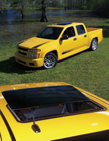
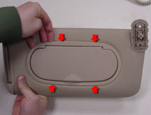
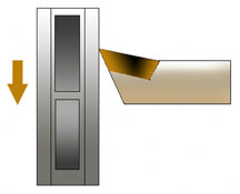
Sunroof
System |
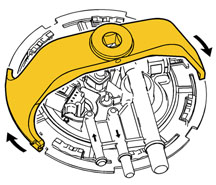
This
information applies to the sunroof system available in the Colorado
and Canyon pickup trucks (fig. 1).
Controls
The power sunroof system is a press-and-hold style system, with no control
module involved. The power sunroof motor is controlled by the sunroof
switch through the open and close motor control circuits.
Ignition voltage is supplied to the sunroof switch (fig.
2) through the retained accessory power (RAP) relay from the
Sunroof 20A fuse in the underhood fuse block. While the sunroof switch
is in an inactive state, both switch contacts are closed to the sunroof
switch ground circuit. When an open or close button is pressed on the
sunroof switch, its switch contact is closed to the voltage supply circuit.
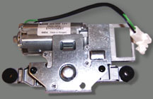
The motor is bi-directional (fig. 3), and
the direction of motor rotation is determined by which of the motor
control circuits is switched to positive voltage while the other remains
grounded.
Operation
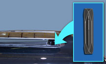
The glass travels from closed to vent to full open position, and can
be stopped in any position by releasing the sunroof switch. As the glass
reaches the open or closed limits, mechanical hard stops inhibit the
travel (fig. 4). The mechanical hard stops
stall the motor into an over-current condition, as an internal motor
device opens. Operation will resume once the over-current condition
is removed, by releasing the sunroof switch.
The glass travel for a regular cab is restricted by panel stops inserted
into the guides. The panel cannot extend beyond the rear edge of the
cab into the bed area. The extended cab and crew cab do not have these
panel stops.
The sunroof can be operated manually with the sun roof emergency crank/sunroof
key. The key and instructions can be found in the owner’s manual
supplement in the glove box.
Other Items of Interest
The sunroof system ground is in the vicinity of the motor, with a self-tapping
screw securing the ring terminal to the front header.
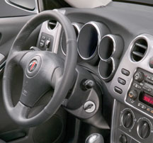
The in-line connector supplying the ignition voltage to the sunroof
switch is located behind the left A-pillar trim (fig.
5).
-
Thanks to Tony Martin |
|
figure
1 |
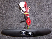
figure 2
|
figure
3 |
figure
4 |
figure
5 |
| return
to Table of Contents |
|
|
| Cadillac
ECM Reprogramming |
When reprogramming the engine control module on a 2004-2005 Cadillac
SRX, XLR, and STS with LH2 4.6L V8 engine, the following points may
be helpful:
1. The battery must be fully charged during reprogramming. Battery voltage
must be above 12 volts. Turn off electrical accessories that may drain
the battery during reprogramming, such as automatic headlamps, daytime
running lamps, interior lights, HVAC system, engine cooling fan, radio,
etc.
2. Ambient and coolant temperature during reprogramming should be above
41° F (5° C). If coolant temperature is below this, the vehicle
will go into reduced power mode on startup, due to insufficient throttle
learn.
3. A P2119 DTC may set after reprogramming due to low system voltage.
4. If the VIN is not properly entered into the ECM, a P0315 will continue
to set until the ECM VIN matches BCM.
5. Any time an ECM, crank sensor, crankshaft and/or engine are replaced,
a crankshaft position variation learn procedure must be performed.
6. After performing a crankshaft position variation learn procedure,
the ECM must do a proper power-down to store the values, or a P0315
will continue to set until values are stored.
Refer to Service Programming System in SI for more information on reprogramming
the ECM and performing the crankshaft position variation learn procedure.
- Thanks to Dave Dickey |
| |
|
|
| |
|
|
Air Bag Module Checkout |
TIP:
This information applies to all vehicles, although it is prompted by
warranty data from Sunfire, Cavalier, Grand Am, Alero and Malibu Classic.
Extra attention is needed if a vehicle comes in for service with the
air bag telltale illuminated. After reading diagnostic trouble codes
and finding that air bag loop faults and/or sensor faults are current,
take the time necessary to troubleshoot the wiring fully. Replacing
the SDM (fig. 6) will not correct the fault
in many situations. A detailed check of continuity for the faulted lines
is necessary.
TIP: Check all
wiring connections before removing and replacing the SDM.
-
Thanks to Tom Nguyen |
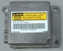
figure 6 |
return
to Table of Contents |
|
| Dexron
VI Followup |
As
a followup to the Dexron VI article in the February TechLink, here are
the current part numbers.
88861003 |
1
quart container |
DEXRON®
-VI
GM Vehicle Care |
88861037 |
1
quart container |
DEXRON®
-VI
AC Delco |
88861004
in Canada |
1
liter container |
DEXRON®
-VI
AC Delco |
GM
began factory-fill of the new transmission fluid on April 4, starting
with the new Hydra-Matic 6L80.
DEXRON®-VI will be available at GM authorized dealerships and service
centers in Summer 2005.
-
Thanks to Susan Leach |
|
| return
to Table of Contents |
|
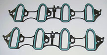
| Upper
Manifold Gasket Leak |
This information applies
specifically to the 5.3L L59 (E85 capable), as well as the other Gen
3 and Gen 4 engines.
If a leak between the upper manifold and gasket causes a DTC P0300 to
set, do not replace the entire upper manifold assembly, upper plenum
and gaskets.
A new gasket made of FNK material (GM SPO p/n 89017589) has been released.
The new gasket material is teal green in color (fig.
7); the original gaskets are orange.
The service kit containing the new gasket was released in October 2004.
A small quantity of the old gasket kit, p/n 17113557, which contains
two p/n 17122608 (orange) gaskets, remains in the system.
Use only the 89017589 gasket (teal green) for repairs on the L59 engine,
and do not replace the upper manifold unless it measures outside of
the service manual specifications or is damaged.
The 17113557 gasket (orange) can be used on the other engines. Once
the 17113557 has been exhausted, only the 89017589 will be available
for all engines. |
figure
7 |
| return
to Table of Contents |
|
| Proper
Method of Measuring Intake Manifold |
SI
states, "An intake manifold with warpage in excess of 3 mm (0.118
in) over a 200 mm (7.87 in) area is warped and should be replaced."
The 200 mm distance will cover two intake ports (fig.
8), not the entire distance of the four intake ports on one bank.
It is incorrect to place a straight edge across the
entire length of the upper manifold, along all four intake runners,
and then replace the manifold when all the runners are not adjacent
to the straight edge.
Unless there is visible physical damage to the upper manifold, or it
measures outside of the service manual specification of greater than
3 mm over 200 mm, it should not be replaced. |
figure
8 |
| return
to Table of Contents |
|
| Sunshade
Vanity Mirror Replacement |
This information pertains to the 2004-2005 Chevy Malibu, Malibu Maxx,
and Pontiac G6.
Customers may comment that the vanity mirror cover breaks during normal
operation. Replace the vanity mirror assembly rather than the entire
sunshade assembly.
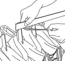
The following procedure may be completed inside the vehicle for non-lighted
sunshades. For lighted vanities, remove the sunshade from the vehicle.
Refer to the Sunshade Replacement procedure in SI.
Insert finger tips or a plastic trim tool tool at the tab locations
to disengage the vanity mirror assembly from the sunshade assembly
(fig. 9).
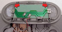
For sunshade assemblies with non-lighted vanities, snap the new vanity
assembly into the sunshade assembly.
For lighted vanities, transfer the circuit board to the new vanity mirror
assembly.
Remove the circuit board from the vanity assembly (fig.
10).
TIP: Slightly
flex the vanity mirror assembly to release the circuit board from the
retaining tabs.
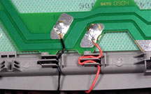
Install the circuit board to the new vanity assembly and route the wire
leads through the wire guides (fig. 11).
Snap the vanity mirror assembly into the sunshade assembly and install
the sunshade to the vehicle.
Parts will be available from GMSPO. Watch for an upcoming service bulletin.
-
Thanks to Joel Ebner |
| |
figure
9 |
figure
10
|
figure
11 |
| |
|
| Programmable
Truck Radios |
This
information applies to 2003-2005 C/K Trucks and Utilities and 2004-2005
S/T Trucks and Utilities. Service programming of the radio on these
vehicles requires the part number of the radio and the appropriate RPO
codes. You can reduce time in programming replacement radios on these
vehicles by following these steps.
1. Before installing a replacement radio, obtain the GM part number
from the label on the radio.
2. Verify that your Tech 2 has the latest software version.
3. Using the Tech 2, "Request Info" from the radio that is
going to be programmed. Always follow proper procedures and precautions.
4. Before entering TIS2000, enter your VIN into GM VIS to obtain the
RPO codes of the radio and speaker configuration for this vehicle. (For
example, verify if the vehicle was built with UQ3, UQ5, or UQ7 speakers,
with or without Y91/Y92.)
TIP: This will allow you to make the correct calibration
selections in TIS2000. Selecting the incorrect calibrations for your
vehicle configuration can damage the radio and lead to unnecessary delays
in repair time.
5. When replacing or installing a NEW radio, you must select "Replace
and Program Module" from the TIS menu.
6. Program the vehicle as usual.
TIP: If you are a valid GM dealer and require assistance
with this procedure, please contact the Techline Customer Support Center
(TCSC).
-
Thanks to Abby Slagor |
|
|
| |
| return
to Table of Contents |
|
| Tire
Pressure Monitor |
A
Tire Pressure Monitor (TPM) system was added to certain GMC and Chevrolet
full-size utility trucks for model year 2004 and continues for 2005.
The same style system will be rolled out on additional vehicles in 2006.
To help you understand this system, a Know-How video was prepared:
Course 10290.04D
Understanding TPM Systems for GM Trucks
March 2005 Emerging Issues
Here are some highlights. For details, refer to the video. A proper
understanding of the system, its components, and its operation will
help you properly diagnose operating conditions. You will learn to determine
when parts replacement and reprogramming are or are not required to
remedy the condition.
TPM System Components
The main TPM system components are:
- DIC
- Passenger Door Module (PDM)
- Instrument Panel Cluster
- 4 pressure sensors
- Serial data circuit
Tire Pressure Sensor Operation
The tire pressure sensors are incorporated into the valve stem of each
road wheel. The pressure sensor transmits a radio frequency message
which is received by a module in the vehicle.
When the vehicle is stationary, the sensor’s internal roll switch
is open, which puts the sensor into stationary mode. The sensor samples
tire pressure once every 30 seconds and transmits once every 60 minutes.
When the vehicle is moving, centrifugal force closes the sensor’s
internal roll switch, which puts the sensor into drive mode. The sensor
samples tire pressure every 20 seconds and transmits every 60 seconds.
Passenger Door Module (PDM) Operation
The PDM is the receiver in the full-size utility truck. The receiver
module varies by vehicle platform. The PDM receives each sensor’s
RF (radio frequency) transmission and translates the data into:
- sensor presence
- sensor mode
- tire pressure.
TIP: If the vehicle
is equipped with RPO UK3, the PDM sends tire pressure and tire location
data over the serial data circuit to the DIC, where they can be selected
and displayed.
In addition to the display of tire pressures, the DIC in full-size utility
trucks can also display two system messages -- “Check Tire Pressure”
and “Check Tire Monitor”. Here are the important differences.
“Check Tire Pressure” message -- If a sensor
detects a 1.6 psi (11 kPa) change in pressure, it transmits in re-measure
mode. If the system detects a significant loss of tire pressure in any
tire, the Check Tire Pressure message is displayed on the DIC and the
low tire pressure indicator is illuminated on the IPC.
TIP: A “Check
Tire Pressure” message will not set system codes. This is normal
operation of the system. The purpose of this message is to alert the
driver to check and adjust tire pressure.
TIP: Both the
message and indicator can be cleared by adjusting the tire pressure
to the recommended pressure.
“Service Tire Monitor” message -- If the
PDM detects a malfunction in the TPM system, it will cause the DIC to
display the Service Tire Monitor message.
TIP: The “Service
Tire Monitor” message is not a normal system operation. DTCs should
be set when this message is displayed.
Tire Pressure Sensor Relearn
DIAGNOSTIC TIPS:
- Try to determine from the customer which message has been displayed.
This is especially important when you cannot find TPM system related
DTCs stored.
- Always check and adjust the tire pressures COLD. As a rule of thumb,
tire pressure will change one psi for every 10° F (6.9 kPa for every
5.6° C).
- Always use a known accurate tire pressure gauge.
- Always ‘relearn’ the system before replacing a suspect
sensor.
Tech 2 Readouts
The Tech 2 can be used for Tire Pressure monitoring information and
functions:
- Display tire sensor IDs
- Display tire sensor mode
- Display tire pressure
- Initiate the TPM Learn procedure
- Set up or change tire pressure placard value for the vehicle
- Set up a Passenger Door Module for TPM operation. A service PDM does
not come ready for use with TPM. This function must be enabled when
a replacement PDM is installed.
When to Perform a Tire Pressure Relearn
The tire pressure sensor relearn procedure must be performed after every
PDM replacement, every sensor replacement, and every tire rotation.
Once the TPM learn mode has been enabled, each of the sensors’
unique ID codes can be learned into the PDM’s memory. There are
two ways to excite the sensors and enter the learn mode.
Pressure Change Method -- This is performed by increasing
or decreasing the air pressure in each tire by a specified amount, which
forces the sensors to transmit in re-measure mode.
TIP: This method
can be reviewed in SI and can also be viewed on the GM Common Training
Website.
J-46079 TPM Diagnostic Tool Method -- Turn the ignition
ON with the engine OFF, and set the parking brake. Place the PDM in
TPM learn mode by cycling the parking lamps ON and OFF 4 times within
4 seconds. The horn will chirp and the low tire pressure indicator will
begin to flash. This indicates the learn mode has been enabled.
Proceed in this order: left front, right front, right rear, left rear.
Starting with the left front tire, hold the antenna of the J-46079 against
the tire sidewall close to the wheel rim at the valve stem, and momentarily
press the activate button.
After the horn chirps, repeat the procedure for the other three wheels.
After all of the sensors have been learned, exit the learn mode by turning
the ignition OFF.
TIP: Before starting
this procedure, ensure that no TPM equipped vehicle nearby is having
its sensors relearned simultaneously, or its tire pressures adjusted.
It is possible for the PDM to learn a stray learn or re-measure mode
transmission from another vehicle’s sensors.
TIP: When a sensor
is changed or relearned, the vehicle must be driven above 20 mph (32
km/h) for the DIC to update.
Sensor Color
In early 2005, sensor part numbers and colors were changed. The 2004
and some early 2005 trucks have a blue color sensor, and most 2005 trucks
have a beige color sensor. If you find an early 2005 truck with blue
sensors, it is not necessary to replace them with beige ones.
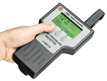
Tool Tip
Here’s a tip regarding your J-46079 TPM Diagnostic Tool (fig.
12).
When the internal battery is fresh (fully charged), the indicator is
“full,” or all dark. When the battery is depleted, the indicator
shows “empty,” or all light.
When the battery is low enough to show empty, the tool may perform some
functions, but not others. For instance, it may perform the Simulate
function, but not the Learn function. If you cannot get a vehicle to
learn, don’t assume the sensors are bad. The tool may just need
a fresh battery.
- Thanks to David Roland and Ken Beish |
| |
| |
| |
| |
| |
| |
| |
| |
figure
12
|
| return
to Table of Contents |
|
| Fuel
Pump Module Lock Ring |
At the start of the 2004 model year, a new 130mm corporate fuel pump
module lock ring was introduced on numerous vehicle programs. In the
future, this fuel pump module lock ring will become standard for all
vehicles requiring a 130mm (5.1 inch) opening for the fuel pump module.
During the engineering development of this lock ring, a J-45722 tool
was created to remove and install the lock ring (fig.
13). The tool is necessary because of the increased installation
forces required to install the ring.
TIP: Never use
any tool other the J-45722 to remove or install the 130mm lock ring.
Never use impact tools with J-45722.
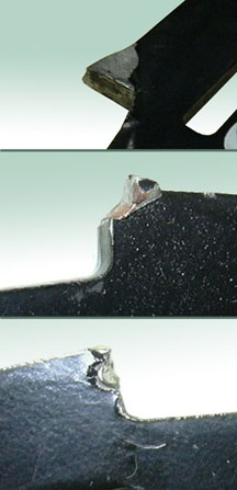
If improper tools such as screwdrivers, chisels, drifts, hammers, or
prybars are used in removal and installation, the lock ring will be
damaged (fig. 14), possibly degrading the
fuel pump module sealing. Damage to the ring may also create sharp edges
that may, in turn, damage the fuel tank. Damage to the tank and sealing
degradation can result in customer comebacks and dissatisfaction.
On some vehicles, the lock ring is captured on the fuel pump module
by line connections or swaged-on lines. In these cases, the lock ring
cannot be removed from the module and cannot be serviced individually.
Some examples of this are the 2004-06 Chevrolet Malibu and MAXX, and
the 2005-06 Pontiac G6. If the lock ring on one of these applications
is damaged, the entire fuel pump module assembly must be replaced.
Inspection of replaced lock rings at the Warranty Parts Center indicates
that numerous 130mm lock rings are being damaged and destroyed by improper
installation and removal methods.
When removing the lock ring, it is important to inspect it for damage
due to improper removal or installation procedures. If damage is found,
install a new lock ring (or the fuel pump module in captured-ring applications).
Don’t replace the lock ring unless it shows damage at the tool
notches or distortion greater than the 0.41mm specification.
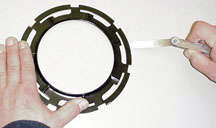
On applications where it is possible to remove the lock ring from the
fuel pump module, place the ring on a flat surface and measure for flatness.
Measure even if damage is not readily visible.
1. Place the lock ring on a flat surface. Measure the clearance between
the lock ring and the flat surface using a feeler gage at 7 points (fig.
15).
2. If the warpage is less than 0.41 mm (0.016 in), the lock ring does
not require
replacement.
3. If the warpage is greater than 0.41 mm (0.016 in) the lock ring must
be replaced.
TIP: Some lock
rings were manufactured with DO NOT REUSE stamped into them. These lock
rings may be reused if they are not damaged or warped.
- Thanks to David MacGillis and Ken Billette |
figure
13 |
 figure
14
figure
14 |
figure
15 |
|
return
to Table of Contents |
|
| Distorted
Rear Fascia |
On a 2000-05 Cadillac DeVille, a distorted or
warped rear fascia may appear after the vehicle has been exposed to
high ambient temperatures. This condition is more prevalent on darker
colors. To correct, replace the rear fascia and follow the repair procedures
outlined in Bulletin 02-08-62-002B, issued on March 10, 2005.
-
Thanks to Bill Denton |
|
|
|
return
to Table of Contents |
|
| Opening
Trunk without Lock Cylinder -- Part 2 |
An
article in the March TechLink discussed how to open the rear compartment
lid of vehicles that don’t have an external lock cylinder, in
case of a fault that prevents using the remote keyless entry or interior
switch. Here’s some additional information.
In the 2004 - 05 Pontiac GTO, there is a secondary trunk release handle
located under the passenger side rear seat head restraint. To access
this handle, lift the head restraint and pull the yellow ring. The vehicle
must not be moving.
-
Thanks to Art Spong and Ken Haneline |
|
|
return
to Table of Contents |
|
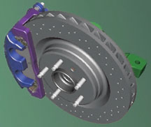
| Cross-Drilled
Rotors |
Cross-drilled brake rotors (fig.
16) are being used on the 2005 1/2 Pontiac Grand Prix GXP, and
available on the 2005 Chevrolet C6 Corvette and the upcoming Cadillac
XLR-V.
If required, these brake rotors can be machined on a lathe in a similar
manner to standard rotors.
TIP: When cutting
rotors, use positive rake tooling on the lathe (fig.
17). Positive rake tooling requires less cutting pressure, reduces
chatter, and improves surface finish. When setting up the brake lathe,
be sure to use a vibration dampener/silencer.
Using SI procedures, apply a non-directional finish to the rotor surface
after machining by using a sanding block and 150-grit aluminum oxide
sandpaper.
-
Thanks to Fred Tebbets and Rob Coultes |
|
figure
16
|
 figure
17
figure
17 |
| return
to Table of Contents |
|
| A/C
System Break-in Process |
Follow
the recommended break-in process mentioned in bulletin 05-01-38-002
to avoid premature A/C compressor wear in the 2005 Vibe A/C system (fig.
18).
Lack of proper lubrication to the new A/C compressor may cause premature
wear or failure in certain conditions on some vehicles in new vehicle
inventory.
This condition is caused by refrigerant system oil migration (causing
compressor wash-out), which occurs on brand new vehicles that have not
had the A/C system on for an extended period of time (typically greater
than 100 days). For vehicles in this category, the A/C system should
not be run until the A/C compressor oil circulation procedure has been
performed.
This condition is not a quality problem that can be fixed simply by
the replacement of the compressor or by the addition of refrigerant
oil to the system. It is a condition caused by the vehicles sitting
outside, in the sun, for extended periods of time. This thermal cycling
causes the oil in the A/C compressor to migrate to the other A/C system
components. Furthermore, this condition does not occur on any A/C components
stored in parts inventory, such as A/C compressors. Continue to use
all service components for this vehicle as normally instructed.
A/C System Oil Circulation Procedure
Do not add additional refrigerant oil to the A/C system.
Perform A/C system operation to ensure proper lubrication of the A/C
compressor during the initial vehicle storage period.
Perform the following sequence to ensure proper lubrication of the A/C
compressor during new vehicle extended periods of inoperation. It is
required that this procedure be performed early in the morning when
the vehicle is cold and the ambient temperature is moderate -- approximately
50°F (10°C).
1. Make sure the air conditioning (A/C button) is off.
2. Put the mode selector in vent mode.
3. Start the vehicle and let engine RPM idle down to slow idle (1000
RPM or less).
4. Adjust the HVAC blower setting to high.
5. Turn on the A/C and allow the system to run for 90 seconds. This
gradual A/C system operation period will allow refrigerant oil to return
to the A/C compressor during critical initial break-in period.
6. Perform A/C system performance check.
IMPORTANT: The
A/C system on this vehicle will not operate when the ambient temperature
is below 35° F (2° C).
It is recommended that vehicles be started and the A/C system operated
(for at least 90 seconds) once per month to ensure proper A/C system
function until the vehicles are delivered or until the vehicle is driven
on a regular basis. Normal operation of the A/C system by the vehicle
owner will allow for sufficient compressor break-in and the oil circulation
procedure should no longer be required.
-
Thanks to Jeff Strausser |
 figure
18
figure
18 |
| return
to Table of Contents |
|
| ABS
And Brake Lights |
On
the 2005 Chevrolet Equinox, the ABS and the brake lights may be on with
no codes set. The vehicle may not have come in for this concern. The
ABS and brake lights may have come on after clearing codes in another
module for an unrelated concern. When the Tech 2 is used, it will show
the EBTCM is commanding the lights on. The condition occurs because
the BCM is no longer broadcasting VIN digits 2-9 on the high speed bus.
1. Disconnect the battery cables from the battery and touch the cables
together for 30 seconds, then reconnect the cables.
2. Check to see if the ABS and brake lights are off, and no codes are
set. Check that you can read the whole VIN using the Tech 2.
3. If the ABS and brake lights are still on with NO codes set, follow
the flow chart for ABS Active Indicator Always On (SI document 1318351).
-
Thanks to Ron Erman and Angelo Girolamo |
|
|
| return
to Table of Contents |
|
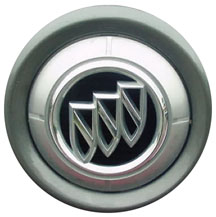
| Emblem
Coming Off Grille |
Owners
of some 2004-05 Buick Rainiers may comment that the Buick emblem (fig.
19) on the grille has come off and is missing.
The clips may not be retaining the emblem to the grille mounting surface.
Replace the emblem by aligning the retaining tabs with the slot in the
grille and apply pressure to the emblem, p/n 89045663, described as
a Emblem Assembly - Radiator Grill. Parts are available from GMSPO.
This is covered in detail in bulletin 05-08-111-001 or SI document 1580217.
-
Thanks to Doug Daugherty |
 figure
19
figure
19 |
|
return
to Table of Contents |
|
| 2005
Gasoline Engine Oil Requirements -- Additions |
2005
GM gasoline engines require the use of an engine oil that has the American
Petroleum Institute (API) Starburst AND states that it meets GM Standard
GM 6094M (non-synthetic) or GM4718M (synthetic). Failure to use the
recommended engine oil can result in engine damage not covered by warranty.
In the March issue, TechLink published a list of engine oil brands that
meet GM Standard GM 6094M and 4718M. This list has be updated through
April 12, 2005 and may be viewed in the TechLink Reference Guide at
http://service.gm.com.
TIP: This list
will be updated in the future as required, and will continue to be displayed
in the TechLink Reference Guide.
-
Thanks to Matt Snider, GM Powertrain |
|
|
| return
to Table of Contents |
|
| Synthetic
Oil Question |
We
recently received this e-mail from Mike McQuoid, at Norman Gale Pontiac
GMC, Cedar Knolls, NJ:
“In the March 2005 issue of TechLink, there is a list of motor
oils approved by GM for use in gasoline engines. I'm curious why so
many “full synthetic” oils are listed in the “non-synthetic”
list and not in the synthetic list.”
Here’s the answer from GM Powertrain:
“GM4718M is General Motors' High Performance engine oil specification.
Oils which meet GM4718M tend to be made from synthetic base stocks,
so it is often referred to as a "synthetic" specification.
“However, not all oils, synthetic or otherwise, are capable of
meeting the stringent requirements of GM4718M. Only the oils listed
on the GM4718M Registered Products sheet have proven their performance
to the specification.”
-
Thanks to Matt Snider, GM Powertrain |
| |
| return
to Table of Contents |
|
| OnStar
Personal Calling Inoperative |
Some
owners of the 2005 STS may comment that OnStar personal calling with
Navigation Radio RPO YQ4 does not work when using the voice recognition
button on the Steering Wheel Controls (SWC). Personal calling will work
from the white dot button on the Inside Rear View Mirror (ISRVM). 2005
Cadillac STS equipped with Navigation Radio RPO YQ4 have Bluetooth phone
capabilities. When pressing the voice recognition button on the steering
wheel controls and saying "phone," "telephone" or
"dial," the system will attempt to connect to the Bluetooth
phone.
In order to connect to OnStar personal calling using the SWC voice recognition
button, the owner must say "OnStar" and then "dial."
-
Thanks to Roger Jantz |
| |
| return
to Table of Contents |
|
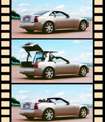
| Power
Folding Top (Retractable Hardtop) |
If
the power folding top (fig. 20) of the 2004-05 Cadillac XLR will
not function,
perform the following.
1. Start the engine and try the top again. This ensures the vehicle’s
battery is sufficiently charged.
2. While depressing the folding top button in the desired direction,
look at the Driver Information Center (DIC) for a message. If a message
is displayed, see DIC Warnings and Messages on page 3-61 in the owner’s
manual for more information.
TIP: Most messages
relating to top operation are displayed only while the folding top button
is depressed.
3. If no messages are displayed and the folding top will not operate,
perform the Power Window Initialize on page 2-17 of the owner’s
manual. The folding top system must know the window position to operate.
The position information can be lost if the vehicle has had a battery
disconnect or a run down battery. After performing this procedure, try
the top again.
4. It the top doesn’t operate, confirm that the hydraulic fluid
bypass valve, located above the pump motor, is in the operating position
(turned clockwise).
5. If the folding top will still not operate, see SI for additional
diagnosis.
-
Thanks to Paul Radzwilowicz |
| 
figure
20
|
| return
to Table of Contents |
|
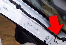
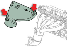
| Exhaust
Manifold Shield Noise |
Owners
of some 2004-05 Chevrolet Colorado and GMC Canyon vehicles with the
3.5L engine may experience a buzz noise while the engine is under load
between 2200 and 2800 RPM. The noise sounds like it is coming from the
engine compartment (may sound like it is coming from the air cleaner
area) or the exhaust system.
Inspect the exhaust manifold for a loose exhaust heat shield. Inspect
all fastener positions, with emphasis on the nut above the O2 sensor
and the nut on the No. 1 exhaust tube (fig. 21).
Make sure the shield itself is not in direct contact with the manifold
other than at the fastener positions. Reposition the shield if necessary
to avoid contact.
-
Thanks to Dino Poulos |
| 
figure
21
|
| return
to Table of Contents |
|
| Torque
Converter Assembly Design Change |
There
is a 4T80E Transmission Torque Converter Assembly Design Change in 2005
Cadillac Deville and Pontiac Bonneville.
Vehicles with the VIN listed below are built with automatic transmissions
that have a new broadcast code and transmission assembly part number.
These transmissions are built with an Electronically Controlled Capacity
Clutch (ECCC or EC3), a new upper control valve body assembly, a new
upper control valve body spacer plate, and a new powertrain control
module calibration.They will not have a viscous fluid converter.
VIN |
Model |
Transmission
Serial Number |
5U189285 |
GXP |
616MMNH0152 |
5U189290 |
DeVille |
616ABNH014H |
5U189292 |
DeVille |
616ABNH014F |
5U189298 |
DHS |
616ABNH014G |
5U189300 |
DeVille |
616ABNH014J |
5U189305 |
DeVille |
616ABNH0146 |
5U189309 |
DeVille |
616ABNH0145 |
5U189313 |
GXP |
616MMNH0154 |
5U189316 |
DeVille |
616ABNH0140 |
5U189319 |
DeVille |
616ABNH013Z |
5U189321 |
DeVille |
616ABNH0149 |
5U189322 |
DeVille |
616ABNH0134 |
5U189326 |
DeVille |
616ABHN0143 |
5U189328 |
DHS |
616ABNH0144 |
5U189331 |
DeVille |
616ABNH0147 |
5U189333 |
DHS |
616ABNH0148 |
5U189334 |
DeVille |
616ABNHO148 |
5U189342 |
DTS |
616MMNH0151 |
5U189356 |
DTS |
616MMNH0155 |
5U189363 |
GXP |
616MMNH0153 |
5U210345 |
DeVille |
615ABNH013Q |
5U210348 |
DeVille |
615ABNH013T |
5U210344 |
DeVille |
615ABNH013P |
5U210340 |
DeVille |
615ABNH013S |
5U210341 |
DeVille |
615ABNH013R |
Use
the current MY 2005 service information and diagnostic procedures for
transmission service requirements. All warranty labor codes and time
allowances remain the same.
IMPORTANT: When
ordering parts for these vehicles, the vehicle VIN, the transmission
broadcast code and the transmission assembly part number must be used.
Remanufactured torque converter part number for transmission code 5ABN,
3.11 axle ratio is 12491371. Remanufactured torque converter part number
for transmission code 5 MMN, 3.71 axle ratio is 12491372.
-
Thanks to Ronald Mitchell |
| |
| return
to Table of Contents |
|
 Car Issues
— Fix It Right the First Time (new issues in bold) Car Issues
— Fix It Right the First Time (new issues in bold) |
Model
Year(s) |
Vehicle
Line(s) --
Condition |
Do
This |
Don’t
Do This |
Reference
Information / Bulletin |
2003-2004 |
CTS
– DTC C0450 or C1241 Set, Service Steering System Message
On |
Replace
only VES solenoid. |
Don’t
replace entire steering gear. |
03-02-36-001A |
2003-2004 |
Cavalier,
Sunfire – Difficult to Adjust HVAC Control Head Mode Dial |
Replace
foam which delaminated from mode door and is causing bind. |
Don’t
replace HVAC control head, module or cables unless damaged. |
03-01-38-005B |
2002-2003 |
Impala
– Snap/Clunk When Window is Rolled to Full Up Position |
Replace
glass run channel with revised P/N. |
Don’t
replace front door window regulator, door glass or align door
glass. |
03-08-64-034 |
2003-2004 |
Cavalier,
Sunfire – Noisy A/C Compressor |
Inspect
for ground-out conditions that can cause A/C compressor noise
complaints. |
Don’t
replace A/C compressor for excessive noise without inspecting
for ground-outs. |
03-01-38-012A |
2005 |
Equinox
LT/LS (AWD Only) – Moan, Bind or Growl Coming from Rear
during Low Speed Parking Lot Turns |
Replace
RDM coupling (clutch pack) with proper sealers. Fill with Versatrak
fluid. |
Don’t
replace complete rear drive module. |
04-04-20-004 |
2005 |
Cobalt/Pursuit
(Built Before January 17, 2005) – Fuel Gauge May Not Go
Completely to Full |
Recalibrate
ECM with updated calibration, version 1.75. |
Don’t
replace fuel module, fuel level sensor assembly or fuel gauge. |
05-08-49-002A |
2002-2005 |
Cars
and Trucks – Multiple Driveability Symptoms/Clogged Fuel
Injectors |
Clean
fuel injectors as described in Bulletin. |
Don’t
replace fuel injectors. |
03-06-04-030A |
2004 |
Grand
Prix – Steering, Suspension or Cradle Click Noise |
Install
new two-piece sleeve and spacer to steering gear mounts. |
Don’t
replace steering gear or cradle. |
03-02-32-048A |
2000-2003 |
Century,
Regal, Lumina, Impala, Monte Carlo, Grand Prix, Intrigue with
3.8L L36 Engine – Coolant Leak |
Replace
upper intake manifold gasket only. |
Don’t
replace upper intake manifold assembly for coolant leak. |
03-06-01-016 |
1999-2004 |
All
Cars and Trucks – Brake Warranty, Service and Procedures |
Issue
One: Refinish brake rotor.
Issue Two: Measure for LRO |
Issue One: Don’t replace brake rotors.
Issue Two: Don’t measure for LRO |
00-05-22-002D |
|
| return
to Table of Contents |
|
|
 Truck
Issues — Fix It Right the First Time
(new issues in bold) Truck
Issues — Fix It Right the First Time
(new issues in bold)
|
Model
Year(s) |
Vehicle
Line(s) --
Condition |
Do
This |
Don’t
Do This |
Reference
Information / Bulletin |
2003-2005 |
Full Size Pickups and Utilities – Rear Seat Audio and/or
Rear HVAC Controls Inoperative |
Replace
RSA. |
Don’t
replace console. |
03-08-44-018B |
2004-2005 |
Midsize and Fullsize Pickups and Utilities – CD Issues |
Load
new software calibration. |
Don’t
exchange or replace radio. |
04-08-44-020A |
2002-2005 |
Tahoe, Suburban, All Yukons, All Escalades, Avalanche, H2 –
Exhaust Pop/Ping Noise |
Replace
heat shield. |
Don’t
replace exhaust system. |
03-06-05-008B |
2003-2005 |
Full
Size Pickups and Utilities – Snap/Popping Noise from Front
of Vehicle |
Use
procedure in Service Bulletin. |
Don’t
replace crossmember. |
03-08-61-002D |
2004 |
Tahoe, Suburban, Silverado, Yukon, Yukon XL, Sierra, Escalade,
Escalade EXT, Escalade ESV, H2 – Passenger Door Module and
RKE Inoperative |
Re-flash
passenger door module. |
Don’t
replace passenger door module. |
04-08-52-005 |
2001-2003 |
Fullsize
Pickups – Injector Replacement for High Flow Rates |
Use
Corporate Bulletin Number 04-06-04-007A for injectors with high
fuel return rates. Use Special Policy 04039 for all 01-02 vehicles. |
Don’t
replace 8 injectors for any complaint other than high fuel return
rates. All other injector failures are fix as failed. |
|
| 2004-2005 |
All
Cars and Trucks – State-of-Charge Upon Delivery of a New Vehicle |
Check
battery’s state-of-charge per revised PDI procedure using
J 42000 or J 42000-EU. |
Don’t
remove and replace battery. |
02-06-03-009A |
| 2002-2004 |
Fullsize
and Midsize Pickups and Utilities – Labor Operation Assignments
for Control Module Reprogramming |
When
submitting claims for reprogramming an electronic module, use the
correct labor operation that reflects the module being programmed. |
Don’t
use K5364, which is for reprogramming a transmission control module
(TCM), when reprogramming a TCCM. |
02-04-21-006D
02-06-04-057D |
| 2002-2004 |
Chevrolet
Avalanche and Cadillac Escalade EXT – Cargo Covers and Cladding
Faded or Stained |
Thoroughly
clean, dry and treat components with “Armor-dillo.”
|
Don’t
replace cargo covers. |
04-08-111-001B |
2001-2004 |
Fullsize
Pickups and Utilities – Servicing Wide Load Mirrors (RPO
DPF) |
Replace
individual parts as needed. |
Don’t
replace complete mirror assembly. |
03-08-64-028 |
|
| return
to Table of Contents |
|
|
| Know-How
Broadcasts for June |
| |
 |
| Know-How
Broadcasts for June |
| 10290.06D
Emerging Issues |
June
9, 2005, 9:00 AM, 12:30 PM Eastern Time
NOTE: Times published in magazine were incorrect. |
| New
Model Features and Technology Close-Up seminars |
Stay
tuned! These programs will return soon. Check the Service
Know-How section of the GM Training website (www.gmtraining.com)
for more details. |
| -
Thanks to Tracy Rozman |
|
|
| return
to Table of Contents |
|
