| |
|
Note: Clicking
on any picture or illustration will open a larger version of that art.
|
|
Remote
Vehicle Start |
The all new 2004
Chevrolet Malibu is GM’s first production vehicle with a Remote
Vehicle Start (RVS) system. (fig. 1) The
option is available on vehicles equipped with RPO AP3. The system has
a range of up to 197 feet (60 meters). (fig. 2)
RVS provides several customer-satisfying features:
- Saves time normally spent scraping ice off windows
- Comfort of entering a pre-heated or pre-cooled vehicle
RVS is integrated with the current anti-theft and RFA systems to provide
a very robust system. And it provides user feedback of the event and
the ability to enable/disable the feature.
Enable and Disable Procedure
The current state of the RVS function can be viewed through the driver
information center (DIC) display. Press the Menu button on the DIC until
REMOTE START appears. The display will read ON or OFF, depending on
the last setting.
To enable the RVS function:
1. Turn ON the ignition, with the engine OFF.
2. Press the Menu button on the DIC until REMOTE START is displayed.
3. Press the Enter button on the DIC until ON is displayed.
To disable the RVS function:
1. Turn ON the ignition, with the engine OFF.
2. Press the Menu button on the DIC until REMOTE START is displayed.
3. Press the Enter button on the DIC until OFF is displayed.
Operation
TIP: The system
must be enabled to operate.
To operate the function, first press and release the LOCK button on
the key fob, then press the RVS button for 2 seconds.
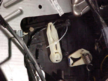
When the remote control door lock receiver receives the start signal,
it sends a GMLAN message to the BCM, and the BCM enables the Run/Crank
relay. Once the relay is turned on, the BCM sends a message to the PCM
to start the engine. The PCM then performs a starter-based algorithm
to start the engine. (fig. 3)
The vehicle park lamps will be illuminated to indicate that the engine
is running. The vehicle doors will be able to be unlocked.
If the engine does not start within three attempts to crank the engine,
RVS will not attempt another start until it is reset. Reset consists
of inserting the ignition key and rotating it to the Run position.
The RVS function is allowed to start the vehicle for two 10-minute intervals.
If the BCM receives a second request for an RVS event while already
operating in RVS, the second timer starts immediately. For example,
if the RVS button was pressed for the first time and then 7 minutes
later the RVS button was pressed a second time, the total time for the
RVS event would be 17 minutes.
To drive the vehicle, the door must be unlocked, and the ignition must
be placed in the RUN position. This unlocks the gear selector lever.
The RVS event can be deactivated:
- by pressing the RVS button on the key fob
- by turning the ignition key from the OFF position to any other position,
then back to the OFF position
- by pressing the hazard switch to the ON position.
There are other safety and security features built into the system.
The following conditions must be met in order for the RVS function to
operate:
- The hood switch inputs to the BCM must indicate that the hood is closed.
- The accelerator pedal is not being pressed during the event.
- There is no current PCM DTC
- There is no current DTC set for the hood switch, hazard switch or
the brake transmission shift interlock (BTSI).
- The hazard switch is in the OFF position.
- There is not a key in ignition input to the BCM.
- The BCM has not lost communication with the PCM.
-The transmission must be in the PARK position.
If any of these conditions are present during an RVS event, the vehicle
park lamps will flash to indicate that the signal was received and the
operation is disabled.
During an RVS event, the engine will be turned OFF if any of the following
conditions are met (the first four serve as anti-theft provisions):
- Throttle position is greater than 10% for 2 seconds.
- Engine speed is greater than 2000 RPM for 30 seconds.
- Engine speed is greater than 4000 RPM for 2 seconds.
- Vehicle speed is greater than 0 km/h
- Engine crank time is greater than 30 seconds
- Engine oil pressure is low.
- Engine is overheating.
- A DTC is set that causes the MIL to illuminate.
- Engine run time has exceeded 10 minutes
- A BTSI Auto Trans Shift Lock Control fault has occurred
- Content theft system is activated
- Hazard switch is turned ON
- The hood is opened
- An ignition switch input fault is detected
- A low voltage condition is detected by the PCM
HVAC Operation, RVS Enabled
The HVAC control module receives three separate GMLAN messages from
the BCM to enable HVAC operation during an RVS event. They include:
Remote
Start Status |
ACTIVE |
Power
Mode Message |
OFF |
Power
Mode Validity |
VALID |
If there is a communication failure between the BCM and the HVAC control
module during an RVS event, the HVAC function will be inoperative.
While in an RVS event, the HVAC control module will not respond to input
of a button press or the turning of a control knob. The LED display
will display AS, referring to the vehicle being in an Auto Start mode.
All other HVAC displays will be disabled. If the A/C is activated, the
LED will not be turned on.
TIP: During the
RVS event, the HVAC system will operate according to the following tables.
However, if the HVAC was turned off the previous time the vehicle was
driven, it will return to OFF as soon as the RVS event ends.
The HVAC control module is programmed to take the following actions
when in an RVS event:
Inside
Air Temperature Input
Below 22°C (72°F) |
Blower
motor |
High
speed |
Mode
door |
Defrost |
Temperature
door |
Full
hot |
Recirculation
door |
Outside
air |
Inside
Air Temperature Input
Above 26°C (79°F) |
Blower
motor |
High
speed |
Mode
door |
Panel |
Temperature
door |
Full
cold |
Request
A/C compressor operation |
Recirculation
door |
Outside
air |
Inside
Air Temperature Input
Between 22°c (72°f) and 26°c (79°f) |
Blower
motor |
Medium
speed |
Mode
door |
Panel |
Temperature
door |
Full
cold |
Request
A/C compressor operation |
Recirculation
door |
Outside
air |
Once the ignition
key is placed in the RUN position, the HVAC system reverts to its last
know setting.
Diagnosis
Refer to SI for appropriate diagnostic procedures. Basically, diagnostics
of the RVS system are based on inputs from other systems, and the RVS
diagnostic tables contain links to faults in those systems.
-
Thanks to Jim Mauney |

figure
1 |

figure 2 |
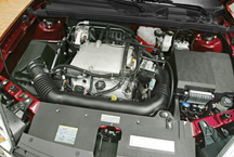
figure 3 |
| |
| |
| |
| |
| return
to Table of Contents |
|
|
| Unable
to Program Replacement PCM |
According to PI01357, when servicing a 1999 Chevrolet Camaro or 1999
Pontiac Firebird, the following diagnosis might be helpful if the vehicle
exhibits these symptoms: Crank No Start, Hesitate, Idles Rough, MIL
/ DTC, No Start, Runs Rough, Stall.
The original or service replacement PCM may not be programmed successfully.
There may also be a DTC P0606 and or a P1516 set. The concern is with
the PCM replacement part numbers.
- Part number 09374997 is mislabeled on the PCM and is part number 09361735,
which is for a non ETC 3800 V-6 application.
- PCM part number 09374997 is for an ETC application but was changed
to part number 12209624.
- PCM part number 12209624 is for a non-ETC application.
- At this time, GMSPO does not have a PCM available for a 3800 V6 ETC
application.
If you are trying to program PCM part number 12209624, 09361735 or 09374997,
call TCSC (1.800.828.6860) and advise the TCSC helpdesk coordinator
that you are not able to program the replacement PCM. TCSC will send
an archive file, which is a software patch that will reset the EEPROM
map for the 1999 F-car. The GM dealer should accept a new PCM part number
to be released into GMSPO service in the near future.
Please follow this diagnosis process thoroughly and complete each step.
If the condition exhibited is resolved without completing every step,
the remaining steps do not need to be performed. If these steps do not
resolve the condition, please contact GM TAC for further diagnostic
assistance. This diagnostic approach was developed for the vehicle with
the VIN you entered and should not automatically be used for other vehicles
with similar symptoms.
-
Thanks to Hassan Abdallah |
|
|
|
| Passkey
III+ Key Data Retrieval |
This
information applies to the 2004 Chevrolet Malibu.
SI document 1352053 contains two procedures for setting up a new Theft
Deterrent Module, within Programming Theft Deterrent System Components.
One procedure uses existing keys and one uses new
keys.
IMPORTANT: The procedure called "Set Up a New Theft Deterrent Module
(TDM) Using Existing Keys" may not function correctly. The corrected
software will not be available on the Scan Tool until CD release 13.
This is due to be broadcast to dealers on December 15. The CD will be
shipped to dealers on approximately December 19.
Until this scan tool release is available, and when using the “Set
Up a New Theft Deterrent Module (TDM) Using Existing Keys” procedure,
it will be necessary to contact Technical Assistance for the necessary
Tech 2 software.
TIP: If the “Set
Up a New Theft Deterrent Module (TDM) Using New Keys” is performed,
the current scan tool setup procedure will function correctly. If a
new Theft Deterrent Module has to be special-ordered, be sure the required
number of keys will be available at the time the new module is installed.
- Thanks to Brent Drendall and Mike McClure |
|
return
to Table of Contents |
| |
| Child
Comfort Clip |
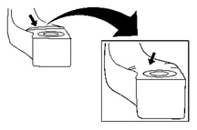
On
Venture, Silhouette, and Montana vehicles, a child comfort clip is sewn
into the rear seats, and is tucked into a fold on the outboard shoulder
seam. (fig. 4) This clip may get damaged
or pull out.
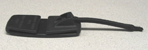
A replacement service clip (fig. 5) for
2002-03 vehicles is available from the Warranty Parts Center, according
to Bulletin 03-09-50-001. It explains how to get the part and how to
install it.
TIP: Install
the replacement clip rather than replacing the seat back cover.
-
Thanks to Tom Geist |
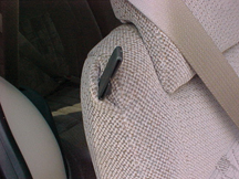
figure 4
|
figure
5 |
| return
to Table of Contents |
|
| Outer
Tie Rod End Service Kit |
This
information applies to:
1997-2001 Buick Century, Regal, Chevrolet Venture, Oldsmobile Silhouette,
Pontiac Grand Prix, Montana
1997-2003 Cadillac Seville
1998-2001 Oldsmobile Intrigue
2000-01 Chevrolet Impala, Monte Carlo
2000-03 Buick LeSabre, Park Avenue, Cadillac DeVille, Pontiac Bonneville
2001-2003 Oldsmobile Aurora
2001 Pontiac Aztek
A new outer tie rod end service kit has been released which is the same
tie rod end that went into production on the vehicles listed above.
The kit includes:
- a revised tie rod end with improved boot that eliminates the possibility
of water intrusion into the tie rod end which can cause premature wear
out condition
- emory cloth
- an instruction sheet.
When replacing the outer tie rod ends, use the improved tie rod end
service kit and modify the knuckles according to this procedure.
- Remove the outer tie rod end from the inner tie rod assembly; count
the number of revolutions it takes to remove the outer tie rod from
the inner tie rod and record it. Discard the outer tie rod end.
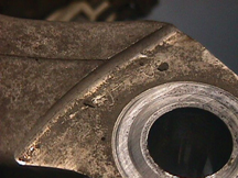
- Use the emery cloth supplied in the service kit to remove the sharp
edge on the knuckle. The photos show the knuckle before (fig.
6) sanding and after (fig. 7) sanding.
IMPORTANT: When sanding
the knuckle, AVOID REMOVING excessive material. USE ONLY the emery cloth
supplied in the service kit. DO NOT use any other abrasive, which may
remove excessive material from the knuckle.
- Ensure that the sharp edge and the flashing on the knuckle are removed
from the outer tie rod end boot/seal area. (fig.8)
- Install the new outer tie rod end supplied in the service kit by screwing
the outer tie rod end onto the inner tie rod end assembly.
- Turn the outer tie rod end as many turns as it took to remove the
old outer tie rod end from the inner tie rod end assembly.
- Install the prevailing torque nut to the outer tie rod assembly.
- Inspect the front toe and adjust if necessary. Refer to Front Toe
Adjustment, SI Document 580777.
-
Thanks to Gary McAdam
Outer
Tie Rod End Service Kit |
89047698 |
Grand
Prix, Montana, Silhouette, Venture |
89047749 |
Park
Avenue, DeVille, Seville, Bonneville, LeSabre, Aurora |
89047697 |
Century,
Regal, Impala, Monte Carlo, Intrigue |
89047756 |
Aztek |
|
figure
6 |

figure
7 |
figure
8 |
|
return
to Table of Contents |
|
| Using
“Getting to Know” Materials Effectively |
"Getting
To Know" your vehicle guides are included in the glove box of most
GM car and trucks sold in the US. (fig. 9)
In addition, some vehicles, like the 2004 Trailblazer, will include
a "Getting To Know" your vehicle CD. The GTK guides are designed
to provide a convenient overview of the operation of the vehicle --
specifically, its features and controls. It is not intended to take
the place of the Owner's Manual.
TIP: New vehicle
preparation personnel should take care to be sure the GTK guide and/or
CD is in the vehicle.
A clear understanding of a vehicle’s operation and features contributes
greatly to a customer’s satisfaction with their new vehicle, and
that’s reflected in J.D. Power and CSI survey results.
GTK materials provide the salesperson an excellent aid when explaining
the features of a new vehicle to the owner during delivery. In the same
way, service advisors and technicians can gain quick insight into a
vehicle’s operating features, from an owner’s standpoint,
by studying the GTK guides.
TIP: Pay particular
attention to the key five J.D. Power customer dissatisfiers: RKE Operation,
HVAC Controls, Audio Systems, Memory and Personalization Features, and
Perceived Fuel Economy.
Electronic copies of the 2004 GTK guides can be obtained by US dealers
on the web at www.gmcommontraining.com.
- Thanks to Diana Sancya |
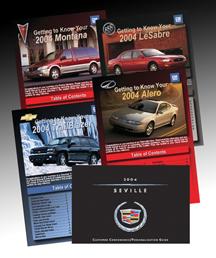
figure
9 |
| return
to Table of Contents |
|
| “Rotten
Egg” Exhaust Odor |
Three conditions
are necessary for "rotten egg" or hydrogen sulfide odor to
be present in exhaust gasses:
- Hot catalytic converter
- Sulfur in the fuel
- Rich air-fuel ratio, at least momentarily.
Of these three, the quantity of sulfur present in the fuel is the most
variable, and most difficult to control for both a vehicle manufacturer
and a customer.
High amounts of sulfur in fuel can cause not only a rotten egg odor
in exhaust gasses, but also certain re-active sulfurs can corrode silver
contacts in the fuel level sender, causing erroneous fuel gauge readings.
At present, there is no EPA requirement for the level of sulfur in fuel,
outside of the state of California, and the ASTM (American Society for
Testing and Materials) specification limit is 1000 parts per million
(PPM). To put that number into perspective, the current limit for sulfur
in California phase 2 gasolines requires an average of less than 30
PPM.
In 2004, the EPA will begin limiting the sulfur content in gasoline.
In 2004, the EPA limit for the corporate average sulfur content will
be 120 ppm, and no single gasoline can exceed 300 ppm (except for small
refiner exemptions). By 2006, the corporate average will be limited
to 30 ppm (the current California limit), with a maximum of 80 ppm (except
for small refiner delays). California Phase 3 gasoline, which will be
available next year, will have a maximum sulfur content of 15 ppm.
In the absence of an identified vehicle condition, customers can be
advised to temporarily change to a premium grade brand of fuel from
a major supplier such as Shell, Exxon, Texaco or Chevron. Premium fuels
in general have been found to have lower sulfur levels. However, even
these suppliers can be susceptible in areas where base fuels are delivered
either by pipeline or from the same refinery.
TIP: Dealers
should refrain from attempting repairs or replacing catalytic converters
for odor complaints, unless there is a MIL indicating a part deficiency.
-
Thanks to Bob Furey and Jay Dankovich
|
|
return
to Table of Contents |
|
| Interior
Light Override Feature |
Customers continue to be confused by the operation of their vehicle’s
interior lights. Many cars and trucks have override switches (fig.
10), which disable the function of interior lights, when light
is not wanted. Customers who are unaware of the switches may assume
the vehicle doesn’t have interior lights or that they are malfunctioning.
Two things will help minimize this confusion.
TIP: During pre-delivery
inspection, be sure the override switch is off, so the interior lights
are not disabled.
TIP: Be sure
the customer understands the functioning of all systems when the vehicle
is delivered.
- Thanks to Tom Geist |
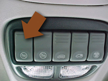
figure
10 |
|
return
to Table of Contents |
|
| Squeaking
Seatback Clip |
On
Buick LeSabres, the rear upper seat back may squeak when pressure is
applied to the back. This is caused by metal to metal contact between
the seat anchor clip and the seat cross brace (fig.
11).
Install mylar or equivalent tape over the seat clip anchor hole, then
reinstall the seat back.
- Thanks to Bill Metoyer
|
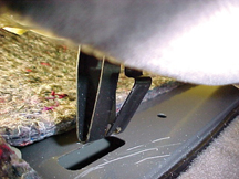
figure
11 |
| return
to Table of Contents |
|
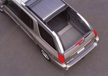
| Envoy
XUV Rear Wiper |
The
2004 Envoy XUV features a unique power sliding rear roof and dual function
end gate with sliding power window (fig.12).
The rear wiper system for this vehicle is designed to park the wiper
arm in a depression, or pocket, in the end gate applique.
“Timing” Procedure
If the wiper arm is removed for any reason, it’s necessary to
“time” the motor assembly before installing the wiper arm
to the vehicle.
TIP: If the timing
is not done, the wiper arm will not park properly, and may interfere
with the operation of the end gate window.
1. With the rear wiper arm removed, turn the igntion to RUN, with the
engine OFF.
2. Turn the rear wiper switch to full speed (position 3) and verify
that the wiper arm pivot shaft is functioning.
3. Locate and remove the rear wiper fuse No. 9, located under the LH
rear seat. Verify that the wiper arm pivot shaft is NOT functioning.
4. Turn the wiper switch OFF.
5. Install fuse No. 9.
6. Turn the ignition to LOCK OFF.
IMPORTANT: Do not turn
on or cycle the rear wiper after step 6 until the wiper arm nut is fully
torqued. If the vehicle is turned on, start over at step 1.
7. Install the washer hose end connection into the end gate, route the
hose clockwise around the shaft and connect to the elbow.
8. Install the rear wiper arm. Align the park finger of the arm into
the park pocket in the applique.
9. Tighten the nut to 6-10 N.m (55-89 in.lb.).
10. Secure the wiper arm nut cover.
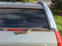
11. Turn the ignition to RUN, engine OFF.
12. Cycle the rear wiper and verify the park location of the wiper arm
into the applique pocket (fig. 13).
13. Inspect the operation of the end gate window.
TIP: SI document
1326065 is being revised to include this procedure.
- Thanks to Brandon Snyder and John Force |
figure
12
|
figure
13 |
| |
| return
to Table of Contents |
|
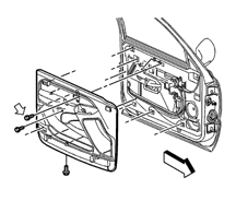
| Trim
Panel Removal |
This
applies to the removal of the front door trim panel on a 2003-04 C/K truck.
TIP: To avoid damage
to the panel, don’t forget to remove the screw hidden behind the
manual lock lever, indicated in figure 14.
This screw is referred to as number 2 in the SI procedure.
TIP: Also refer
to the Switch Plate Bezel Removal article in the July 2003 TechLink for
more information on servicing these door panels properly.
-
Thanks to Mark Freigruber |
figure
14 |
return
to Table of Contents |
|
| Seat
Belt Extender |
A
change was made to the seat belt system on Venture, Silhouette, and
Montana models in October, 2002. Model year 2003 vehicles built before
October 7 had 2002 parts, and those built after October 7 have the new
parts. The parts are not interchangeable. New retractor-side and buckle-side
belts give better insertion effort and improve customer satisfaction
with seat belt operation.
Seat belt extenders are now available for the new design seat belt system.
If a customer has a vehicle built after 10/7/02 and needs a seat belt
extender, use the new part numbers listed below.
-
Thanks to Tom Geist
Part
Number |
Description |
88956963 |
Extension
Kit, Front Seat Belt (9 inch) |
88956964 |
Extension
Kit, Front Seat Belt (15 inch) |
|
|
return
to Table of Contents |
|
| Resistance
Calculated Oxygen Sensor Heater Temperature (RCOHT) |
On
some vehicles, GM is using a relatively new oxygen sensor temperature
control strategy called RCOHT (Resistance Calculated Oxygen Sensor Heater
Temperature).
TIP: It’s
important to perform a reset procedure after replacing an oxygen sensor
on a vehicle using RCOHT.
How does RCOHT work?
The RCOHT strategy will learn the resistance of the oxygen sensor heater
circuit, at start-up, after a cold soak has occurred. At start-up, the
engine controller briefly samples the oxygen sensor heater current; it
then calculates the resistance of the oxygen sensor heater, based on the
sampled current and the measured supply voltage (system voltage). Once
the initial resistance is known, a resistance-to-temperature model can
be followed as the calculated resistance changes during operation. From
this model, the engine controller can very accurately control the temperature
of the oxygen sensor heater.
An expected range of oxygen sensor heater resistance characteristics is
stored within the engine controller for that specific package. The engine
controller must know the initial resistance of the heater in order to
determine which resistance model to follow. The initial resistance calculation
can be made only after an extended soak period, so the engine controller
can accurately determine the equivalent “room temperature resistance”
of the oxygen sensor heater. This “room temperature” is based
on the engine coolant temperature sensor (ECT) and intake air temperature
sensor (IAT) values. In other words, the engine controller can safely
assume that when the extended soak conditions have been met, the oxygen
sensor will be at the same temperature as the ECT and IAT. Although not
specific to any particular platform, an extended soak can be roughly defined
as: The engine has been off for more than 10 hours AND the ECT and IAT
are within 8° C (14.4° F) of each other at start-up.
Why use a new strategy?
RCOHT provides much more accurate control of the oxygen sensor heater
temperature. Other temperature control strategies attempted to “predict”
the oxygen sensor temperature by using some form of a temperature prediction
model.
RCOHT allows accurate oxygen sensor heater control even if there is a
resistance variation between newly manufactured oxygen sensors or if the
resistance changes as the sensor ages. One problem faced in the past was
the possibility of over predicting the heater temperatures of a high resistance
oxygen sensor and the possibility of under predicting the heater temperatures
of a low resistance oxygen sensor. Because the engine controller is now
calculating the resistance of the oxygen sensor after each extended soak,
the temperature of the sensor heater can be more accurately controlled
throughout the life of the sensor.
What happens if there is a failure with the heater circuit or
the engine controller does not learn the sensor resistance?
A gross failure (open, short to ground, short to voltage) on the heater
circuit should set a heater driver code (P0030-0058) and/or a heater current
monitor code (P0135, P0155, P0141, P0161). If there is a high resistance
condition within the heater circuit, it is possible the engine controller
will learn an incorrect heater resistance value and not set one of the
above DTCs. At this time, no dedicated DTC will set for this particular
failure! On some applications, a failed learn or an incorrect learn will
cause DTC P0135, P0155, P0141, or P0161 to set. The diagnostic tables
for these DTCs have taken this possibility into account and will provide
appropriate testing procedures. Some vehicle applications do not report
a failed or incorrect resistance learn to the previously mentioned DTCs.
In these applications, the following DTCs may set in the event of heater
degradation or failure: P0133, P0153, P0136, P0156, P0140, P0160.
On certain applications, starting in the 2005 model year, there will be
specific DTCs (P0053, P0054, P0059 and P0060) for a failed learn or a
learned resistance that is out of range.
What to do when an oxygen sensor is replaced?
When a new oxygen sensor with the same part number is installed, it may
have a different heater resistance than the previous sensor. In most cases,
an extended soak does not occur, nor is it realistic to expect it to occur,
immediately after oxygen sensor replacement. However, we do not want the
engine controller to control the new sensor based on the calculated resistance
of the old sensor. This may cause under or over prediction of the heater
temperature of the new sensor. Therefore, some type of reset procedure
is required to prevent the possibility of heater damage (high temperature)
to the new oxygen sensor. This will allow the vehicle to be returned to
service as quickly as possible.
TIP: To reset the
oxygen sensor learned resistance, a code clear is required. The reset
procedure is required after the sensor is replaced, REGARDLESS OF WHETHER
OR NOT ANY DTCs ARE PRESENT!
When a reset procedure is performed, a default resistance value will be
used until an extended soak occurs. This default resistance will allow
the new sensor to operate without the possibility of heater damage until
an extended soak occurs.
Summary
More and more engine applications will incorporate the use of the RCOHT
strategy.
TIP: Refer to the
appropriate service manual oxygen sensor diagnostic information and replacement
procedures for the vehicle you’re servicing. This will provide you
with a notice to perform a code clear after sensor replacement.
In the future, there will be a scan tool feature available to reset the
learned resistance without performing a code clear.
-
Thanks to Jim Hanna, O2S Signal Delivery Subsystem Team |
| return
to Table of Contents |
|
| Memory
Seat Calibration |
On
vehicles with memory seats, the memory seat module uses position sensor
inputs to establish soft stop locations for the adjuster motors, several
millimeters ahead of the physical limits of the adjuster assembly. After
replacing a memory seat module or adjuster components, it may be necessary
to reset the adjuster motor soft stop locations. When the repair procedure
has been completed, operate the seat adjuster switch in every direction
until the seat adjuster reaches its mechanical hard stop, by repeatedly
pressing and releasing the switch as necessary.
-
Thanks to Devin Koski |
| return
to Table of Contents |
|
| Oil
Viscosity Usage |
For
2003 L36 and L67 engines, the vehicle owner’s manual recommends
10W30 motor oil, while the engine oil fill cap may state to use 5W30 motor
oil.
For the 2003 model year, 10W30 or 5W30 motor oil is appropriate for the
L36/L67 3800 applications. The use of either 10W30 or 5W30 motor oil will
provide necessary lubrication for engine component wear protection.
-
Thanks to John Fletcher |
| |
| return
to Table of Contents |
|
| AC
Vent Louver Repair |
The
2000-04 Impala and Monte Carlo I/P trim plate has integrated A/C vents
that are not serviced separately. Many trim plates are replaced for inoperative
louvers in the vent assembly.
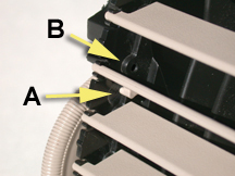
If the round peg on the end of a louver has come out of its mating hole
in the thumbwheel actuator, the louver will not open or close when the
thumbwheel is turned (fig. 15).
A Peg on louver
B Hole in actuator
To avoid unnecessary replacement of the I/P Trim Plate, shine a light
into the vent and see if the inoperative louver still has the round peg
on the end. If the peg is still present, flex the louver, reinstall the
peg into the thumbwheel actuator, and check for correct operation.
-
Thanks to Gary McAdam |
figure
15 |
| return
to Table of Contents |
|
| Poor
HVAC Blower Vent Performance |
According
to bulletin 03-01-38-013, owners of some 2002- 03 Buick Rendezvous and
2001-03 Chevrolet Venture, Oldsmobile Silhouette, and Pontiac Aztek and
Montana may comment that the airflow volume from the dash vents is noticeably
reduced when switched from cold to hot. Also, hot airflow volume may seem
less from the dash vents when compared to the floor ducts.
The following procedure may improve the above condition by disabling the
temperature sub damper door.
1. Move HVAC temperature settings to full cold position.
2. Remove passenger side lower instrument panel trim, glovebox and door,
and hush panel. The passenger side actuator should be visible.
3. Disconnect actuator connector. Remove 2 actuator screws and actuator.
4. Remove 2 screws that hold the actuator mounting plate to the module.
Remove the plate, exposing the levers underneath.
5. Carefully remove mode door lever by lifting the mode lever locking
tab at pivot point and simultaneously pry outwards on the base of the
lever with a flat screwdriver. Pry as close to the shaft as possible.
Remove and discard. With the mode lever removed, swing the temp sub-damper
lever fully up. This opens the door fully on the inside of the HVAC case.
6. To keep the sub-damper door fully open, use a small plastic tie strap
to fasten its lever to the upper actuator attachment boss (fig.
16). Loop the strap through the channel of the lever and around
the upper actuator attachment boss. Make sure to get the strap over the
side ribs, as the side ribs are the locating feature for the actuator
backing plate. Ribs used as actuator backing plate locating feature must
not be obstructed by tie-strap.
7. Install actuator mounting plate.
8. Install temperature actuator.
9. Reconnect actuator wiring connector. Cycle the temperature door from
full cold to full hot a few times and check proper operation.
10. Reinstall passenger side lower instrument panel trim, glovebox and
door, and hush panel.
-
Thanks to Phil Race |
figure
16 |
| return
to Table of Contents |
|
 Car Issues – Fix It Right The First Time
 |
Model
Year(s) |
Vehicle
Line(s) --
Condition |
Do
This |
Don’t
Do This |
Reference
Information / Bulletin |
2000-2004 |
Cavalier/Sunfire
– O/S Rearview Mirror Vibration |
Align
insulator patch and tighten nuts to specification. |
Don’t
replace the entire mirror assembly. |
03-08-64-011A |
2003-2004 |
Venture/Montana/Silhouette
– Alarm Goes Off (Non Theft Deterrent-Equipped Vehicles
(UA6)) |
Disable
the theft deterrent using the owner’s manual directions. |
Don’t
replace the MALL module. |
03-08-64-004 |
2004 |
Grand
Prix with Monsoon Audio System – Speaker Buzz |
Re-pin
the speaker wires in the I/P fuse panel connector. |
Don’t
replace the speaker, amplifier or radio. |
03-08-44-015 |
2003-2004 |
Impala/Monte
Carlo – Condensation in Headlamp |
Normal
condition when limited to fog or fine mist appearance in high
humidity conditions. |
Don’t
replace the headlamp assembly when no water droplets are evident. |
01-08-42-001
September 2000 TechLink |
2003-2004 |
CTS
– Variable Effort Steering (VES) “Service Steering
Message,” DTC C1241 or C0450 |
Replace
the only the VES solenoid. |
Don’t
replace the entire steering gear. |
03-02-36-001 |
2003-2004 |
Vibe
– Normal Exhaust Odor |
Provide
a copy of the service bulletin to the customer. |
Don’t
replace the catalytic converter. |
03-06-05-006 |
1998-2004 |
All
Cars and Trucks – Wabasto Sunroof |
Repair
the sunroof module. |
Don’t
replace the sunroof module. |
03-08-67-004 |
1997-2004 |
Grand
Am/Alero/Malibu – Brake Pulsation |
Turn
rotor and brake align procedure |
Don’t
replace brake rotor for pulsation |
00-05-23-002
01-05-23-001 (Know How Video #15040.01B) |
2003 |
All
cars with 4T40/45E, 4T65E and 4T80E – Code P0742 |
Replace
TCC PWM Solenoid |
Don’t
replace transmission or valve body assembly |
02-07-30-039B |
2004 |
L61
EcoTech 4 Cylinder-2.2L Engine – Misfire, DTC P0300 |
Replace
spark plug sets |
Don’t replace PCM or ignition cassettes |
Recall
03042 |
|
| return
to Table of Contents |
|
|
 Truck Issues – Fix It Right The First Time
|
Model
Year(s) |
Vehicle
Line(s) --
Condition |
Do
This |
Don’t
Do This |
Reference
Information / Bulletin |
2002-2004 |
C/K Fullsize Pickups and Utilities – Tail Lamp Socket Circuit
Board |
Replace
both tail lamp circuit boards with P/N 16532713 (TrailBlazer,
TrailBlazer, EXT), P/N 16532716 (Envoy, Envoy XL) or P/N 16532715
(Rainier, Bravada). |
Don’t
replace the complete tail lamp assembly. |
Service
VME, 9/22/03
03-08-42-006A |
2003-2004 |
Fullsize Pickups and Utilities – Door Trim Panel |
Remove
the front door panel then remove the switch bezel retaining screw. |
Don’t
pry the switch bezel out of the door trim panel without first
removing the retaining screw. |
Service
VME
03-08-64-022 |
2003-2004 |
Fullsize Pickups and Utilities – Servicing Wide Load Mirrors
(RPO DPF) |
Replace
individual parts as needed. |
Don’t
replace the complete mirror assembly. |
03-08-64-028 |
2002-2003 |
All
TrailBlazer, All Envoy, Bravada – Windshield Washer Nozzle |
Replace
with windshield washer nozzle P/N 15173510 |
Don’t
replace the complete cowl assembly. |
Service
VME dated 06/25/2002 |
2003 |
Fullsize Pickups and Utilities – Transfer Case Service Light |
Replace
encoder motor sensor and reprogram TCCM |
Don’t
replace the module, encoder motor or transfer case for DTCs C0327,
P0836, P0500 |
03-04-21-001B |
2003 |
Fullsize
Pickups – 6.6L Diesel Engine ECM |
Follow
SI and bulletins for proper diagnostics for P0181. Refer to the
Owner’s Manual (block heater and front cover) |
Don’t
replace ECM (DTCs P0540 and P0181) unless diagnostics confirm
need to replace |
02-06-04-048,
03-06-04-021, 02-06-04-058 and parts restriction |
2003 |
Silverado,
Sierra, Savana, Express > 8600 GVW – ABS Lamp On |
Reflash
for code C0550 |
Don’t
replace ABS module |
03-05-25-003
and parts restriction |
2002-2003 |
TrailBlazer,
TrailBlazer EXT – Wavy Front Fascia |
Repair
fascia with Dual Lock |
Don’t
replace front fascia |
02-08-62-004 |
2002-2003 |
All
TrailBlazers, All Envoys, Bravada – Mirror Erratic Return |
Replace
mirror actuator and reprogram module |
Don’t
replace outside mirror assembly |
02-08-64-008
02-08-64-021 |
2002-2003 |
TrailBlazer,
Envoy, Bravada without G67 – Moan/Boom |
Replace
rear coil springs |
Don’t
repurchase vehicle for rear axle vibration/boom noise |
02-03-09-002A |
|
| return
to Table of Contents |
|
|
| Know-How
Broadcasts for December |
| |
 |
| Know-How
Broadcasts for December |
| 10270.12D
Emerging Issues |
December
11, 2003 |
9:00
AM, 12:30 PM,
3:30 PM
Eastern Time |
| 10270.24D
- CTS-V 6-Speed Manual Transmission |
December
18, 2003 |
9:00
AM, 12:30 PM,
3:30 PM
Eastern Time |
| -
Thanks to Tracy Timmerman |
|
|
| return
to Table of Contents |
| |
