|
|
Note: Clicking
on any picture or illustration will open a larger version of that art.
|
|
Pontiac
Vibe Tips |
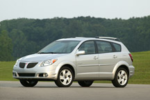
This
information applies to the Pontiac Vibe (fig.
1).
EVAP System Diagnostic Concerns -- Technicians may encounter difficulties
in diagnosising EVAP system leaks.
A great resource for U.S. technicians for additional helpful tips is
found at this web address: http://beta.gmcommontraining.com. Click
on TechAssist in the left column, then look under Emerging Issues.
Review the material from the February 2004 Know-How telecast.
TIP: This system was also explained in the November 2002 TechLink.
Water Leaking on the Front Passenger Carpeting -- Owners may comment
that the passenger’s front carpeting gets wet. The source of
the leak may be a disconnected HVAC evaporator drain tube. To correct
the condition, attach the drain tube (fig. 2) and secure with a plastic
tie-strap.
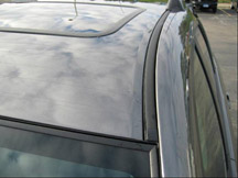
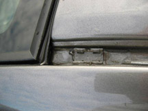
Water Leaks from the Roof -- Owners may comment that there is water
dripping from the front A-pillars or the headliner. The source of the
leak may be an improperly sealed roof seam. The roof seam is located
under the black rubber seal that runs from the front to the rear of
the vehicle.
TIP: This leak may be misdiagnosed as a sunroof water leak.
1. Remove the Black Mohawk Molding (fig. 3) and the luggage rack to
gain access to the roof’s body seam. Carefully pry the front
edge of the molding up. Be careful not to damage the retaining clip,
molding, and windshield.
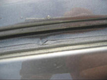
2. After the molding has been removed, inspect the roof seam for skips
or voids in the seam sealer (fig. 4).
TIP: To help speed the diagnostic time, run water along the complete
length of the seam. You may be able to see the skip in the body seam
sealer.
3. Be careful not to damage the nylon retaining clip. If the water
leak is coming from the front edge of the roof panel (fig.
5), the
windshield will have to be removed.
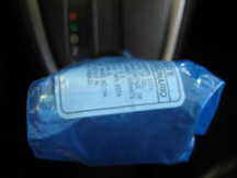
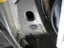
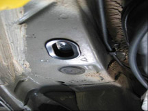
PDI Tips -- Two key items are still being overlooked during the Vibe’s
PDI process: installation of the shifter override plastic button and
the rear body plugs. See Service Bulletin 03-00-89-004.
1. The shifter override release button is attached to the paper tag
under the plastic protection for the shifter knob (fig.
6).
2. If the shipping hole plugs are not installed (fig.
7), owners may
comment that the vehicle has excessive road noise, or the rear passenger's
carpet gets wet. Plugs must be installed in the holes used for shipping
hooks during transportation of the vehicle (fig.
8).
Automatic Headlamp -- Owners of 2003-04 Vibes may comment that the
automatic headlamp system does not turn the headlamps on when the vehicle
is started during low light conditions.
A revised DRL module has been released to turn the headlamps on when
the vehicle is started. The part number for the new module is 88973265.
- Thanks to Jeff Strausser |
|
figure
1 |
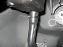
figure 2 |
figure
3 |
figure
4 |
figure
5 |
figure
6 |
figure
7 |
figure
8 |
| return
to Table of Contents |
|
|
| Chevrolet
Aveo Tips |
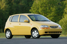
This information pertains to the Chevrolet Aveo
(fig. 9).
Clock Concerns -- Owners may comment that their clock intermittently
resets to 1:00 o’clock, or loses time. Changes were made to the
clock’s circuit board to correct these concerns. The new clock
assembly is p/n 96434566.
Radio Anti-Theft Code Deletion -- Aveos no longer have the radio anti-theft
card inside the glove box. Aveos built after April 12, 2004 no longer
have the radio theft feature. The VIN breakpoint was 4B574659. This
was implemented to improve customer satisfaction.
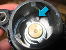
MIL Concern, P0128 Stored, Heater Performance -- Owners may comment
that the MIL stays on with code P0128 stored, or that the heater doesn’t
get hot enough.
The cause may be a stuck thermostat due to aluminum flashing from the
cylinder head. To correct this concern, remove the loose piece of aluminum
from the thermostat (fig. 10).
Power Door Locks/RKE Inoperative -- Owners may comment that their power
door locks and RKE system do not work. The 15 amp fuse for the power
door lock circuit may be open. The fuse is located in the left side
instrument panel fuse panel. To correct the concern, follow Service
Bulletin 04-08-52-004.
- Thanks to Jeff Strausser |
figure
9
|
figure
10
|
| |
|
|
SI Transition to the Web |
In
recent years, one of the most common requests to GM Service and Parts
Operations has been to provide daily updates to the SI web site.
On June 26, 2004, this became a reality. Daily updates include Service
Bulletins, Campaigns, PIs and Service Manuals. The daily updates
allow access to the most current service information available in
the industry. The benefits of up to date information in the hands
of our technicians include:
- Well-informed technicians who have timely access to “the factory’s” concerns.
- Increased vehicle owner confidence with technicians using the most
current information.
- The increased ability to fix the vehicle right the first time and reduce
customer comebacks and cost.
Web utilization of SI is rapidly increasing, with over 3 million hits
per day and climbing. A recent survey of all U.S. dealerships indicates
that more than 89% of U.S. dealers are utilizing high speed Internet
access in the service bay.
Timeline for Transition
Beginning January 1, 2005, all U.S. dealers will be asked to use the
SI web site as their primary source for GM Service Information. With
SI web as the primary source for information, future efforts will be
focused on enhancements and site performance. Throughout the transition
to SI web as primary, various communications will be provided to our
dealers.
During the week of October 8, U.S. dealers received their final set of
SI CDs, labeled November 2004. It contains an application CD and six
data CDs. A sticker on the shipping box indicates the SI web site will
be the primary source for SI starting January 1, 2005. This new base
set of CDs will be incrementally updated weekly, via GM ACCESS, until
early February 2005.
Following the November 2004 release of SI, the application will transition
in 2005 to a quarterly DVD to be used for backup purposes only. A PC
with a DVD drive will be required to use SI on DVD. Details concerning
SI on DVD will be communicated shortly.
In the past several months, GM SPO has strongly encouraged dealer participation
in the Multiple PC Initiative (MPI). MPI participants meeting the recommended
2:1 ratio have seen measurable increases in CSI and service stall efficiency,
with increased availability of Techline applications such as SI web and
TIS.
- Thanks to Bob Savo and Lisa Scott |
|
return to Table of Contents |
|
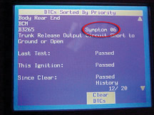
| DTC
Symptoms, Revisited |
This
topic was first mentioned in the September 2003 issue of TechLink.
Briefly, due to the way DTC numbers were issued in the past, the list
of numbers available for DTCs used on GM vehicles worldwide was being
rapidly depleted. So, when the GMLAN communication system was being developed,
a method was found to include additional data in each DTC message. This
permits more information about a circuit failure to be displayed on the
scan tool without needing additional DTC numbers. The extra data is called
the DTC Symptom (fig. 11).
DTC symptoms are displayed as two additional alphanumeric characters,
immediately after the traditional DTC.
The first character indicates the DTC symptom category, and the second
character indicates the subtype.
TIP: A complete DTC Symptom Description is found in SI for each vehicle
to which it applies. Follow this path:
- “Build” the vehicle
- Vehicle Control Systems
- Vehicle DTC Information
- Description and Operation
- DTC Symptom Description
TIP: You can view one such list on SI under document ID 1250630.
IMPORTANT: When you’re working on a vehicle that displays DTC symptoms,
be aware that the DTC symptoms contain information that should be provided
on repair orders and warranty claims, and should be reported when talking
with Technical Assistance. Engineers consider the DTC symptoms as a part
of the DTC and write them as part of the DTC, separated by a space.
EXAMPLE: B3265 06
- Thanks to Bob Johncox and John Mason
|
figure
11
|
| return
to Table of Contents |
|
| Tech
2 Extended Warranty |
REMINDER -- Your new Tech 2 comes
with a two-year manufacturer Express Exchange Warranty. You can extend
the warranty, giving you a full five years of warranty coverage.
TIP: The extended
warranty does not cover cables, adapters and PCMCIA cards.
Even if you do not presently have any warranty coverage on your Tech
2, you can purchase an Extended Warranty for 1, 2 or 3 years of coverage.
During the term of your warranty coverage, there are no charges for
repairs performed to your Tech 2. And, you are guaranteed a 24-hour
Express Exchange Warranty replacement service. If you have a problem
with your Tech 2, simply call the GM Techline Customer Support Center
(1.800.828.6860) and you will receive an Express Exchange replacement
unit the next business day at no additional charge (for requests received
before 3 p.m. PST).
Contact 1.800.GM.TOOLS (468.6657) for additional information and Canadian
pricing.
Compare:
|
Warranty Service
(with Extended Warranty)
|
Regular Repair
(without warranty)
|
Repair Time |
24 hrs. (replacement unit arrives the following morning) |
4-6 days |
Administration |
None. One phone call gets you a replacement unit and return shipping. |
Delays in getting repaired unit; i.e., issuing check, etc. |
Costs |
Extended Warranty Pricing valid
through Dec. 31, 2004
1 year $150.50
2 years $280.00
3 years $407.00
|
Approximately $785 average repair, plus return shipping charges. |
|
|
| return
to Table of Contents |
|
| Grand
Prix Mirror |
According
to bulletin 04-08-64-009, individual components are available for
the 2004 Grand Prix outside mirror.
Do not replace the entire mirror assembly when replacing only the mirror
glass or motor will correct the customer concern.
TIP: The mirror housing material was designed to flex on impact to reduce
the chance of housing breakage or damage to the door sheet metal. But
because the housing is more flexible, a high force impact can result
in the mirror glass being struck by the housing as it flexes, especially
on the outboard side, but the housing doesn’t break. This may cause
one or more of the retention points on the motor to separate, leaving
the mirror loose but not always causing the mirror to fall out.
TIP: In the case of intermittent operation concerns, if the mirror switch
is pushed at the edge of the dished out arrow, the switch will not engage
the mirror motor. This could give the indication that the mirror operation
is intermittent when in fact it is functioning correctly.
-
Thanks to Fred Tebbets
Part Number |
Description |
88987556 |
Mirror Glass -- Right |
88987557 |
Mirror Glass -- Left |
88987558 |
Motor |
|
| |
|
return
to Table of Contents |
|
| Glass
Cleaning Process |
Owners of some Chevrolet Monte Carlo/Impala,
Buick LaCrosse and Pontiac Grand Prix vehicles may comment about a
film or haze on inside window surfaces when the vehicle is delivered.
This film results from a manufacturing process, and is most visible
when headlights or sunlight shine directly through the glass. Because
the film attracts moisture from the air, it can contribute to reduced
visibility under humid conditions.
To ensure high customer satisfaction with the new vehicle, the windows
should be properly cleaned during the final Pre-Delivery Inspection,
just before customer delivery.
TIP: The following procedure has been developed specifically for the
vehicles listed above, but can be used successfully on any vehicle.
Step 1. Spray the entire glass surface of one window with water. Because
the oily film is water-soluble, it should be removed when the glass
is thoroughly wet. For this reason, do only one window at a time. You
don’t want the glass to dry until you wipe it.
TIP: Use regular water only. Avoid any type of chemical cleaner. Use
a clean, empty spray bottle, which can be purchased at home supply
stores.
Step 2. Use dry paper towels to wipe the window. To do this, fold a
sheet of paper towel in half, and wrap it around a dry sponge.
TIP: Use a paper towel only. Avoid any type of cloth.
TIP: Use a sponge about 3 x 5 inches (76 x 125 mm). It should be about
the size of your hand. If it’s too large, the edges of the towel
won’t wipe well. If it’s too small, your fingers may touch
the glass.
The sponge will apply uniform pressure on the glass and by following
its curvature will reduce finger-created streaking.
Step 3. Wipe/dry the glass surface in a uniform, linear, length-wise
fashion, one swipe at a time. Avoid circular swipes. The idea is to
lift the oily film into the paper towel without spreading it around
by multiple swipes.
IMPORTANT: Discard each sheet of paper towel after one swipe.
-
Thanks to Vass Theodoracatos |
| |
|
return
to Table of Contents |
|
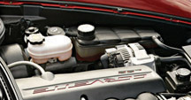
| Low
Coolant System Operation |
The
2005 Chevrolet Corvette utilizes an algorithm-based low coolant level
system which eliminates the need for the coolant level sensor previously
positioned inside the surge tank (fig. 12).
The algorithm (a mathematical calculation) measures the difference in
engine coolant temperature readings over time as a function of engine
speed, to determine if the cooling system has a low coolant condition.
After vehicle start-up, the ECM sends an engine RPM and engine coolant
message through the BCM to the HVAC control head. The HVAC control head
uses engine coolant temperature and engine RPM to determine if an increase
in coolant temperature is due to a low coolant level condition.
This system is capable of losing 2 full liters of coolant before triggering
the Low Coolant warning message. Because the surge tank holds approximately
0.8 liters when filled to the proper level, it's possible that a Low
Coolant warning message is not triggered, even though the surge tank
is completely dry.
TIP: After filling a system that has triggered the Low Coolant indicator
message, the ignition must be cycled to turn the Low Coolant indicator
off.
Diagnostic Tips
In the event that the Low Coolant message is present and the coolant
is not low, verify that the RPM and Coolant Data (GMLAN) sent to the
BCM matches the RPM and Coolant Data (Class 2) sent to the HVAC control
module. If the RPM and Coolant GMLAN and Class 2 Data do match, the HVAC
Module software needs updated. If the RPM and Coolant GMLAN and Class
2 Data do not match, the ECM and BCM software need updated.
TIP: This assumes that there are no RPM or Coolant codes set and no other
messages or symptoms are present.
Always refer to SI for the latest service information before conducting
any repairs.
-
Thanks to Chris Semanisin |
figure
12 |
| |
| return
to Table of Contents |
|
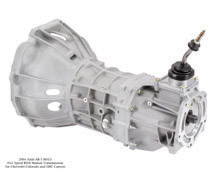
| Manual
Transmission Shifting |
This
information applies to 2004-05 Chevrolet Colorado and GMC Canyon
pickups, equipped with the 5-speed manual transmission, RPO MA5 (fig.
13).
Some owners may comment on difficulty in shifting into reverse. The Aisin-built
5-speed manual used in these vehicles does not have a synchronized reverse.
Instead it uses a sliding idler gear and a brake system to slow down
the shaft before reverse gear is engaged.
A customer may notice three things when shifting into reverse. All are
normal operation.
1. If the driver moves from the neutral position into the 5th/reverse
gate and leans the shifter toward 5th before heading toward reverse,
this will block out reverse. A lock-out mechanism prevents shifting directly
from 5th to reverse.
2. Although the driver operates the shifter correctly, on some occasions
the idler may slide and block the shift due to side to side contact between
the gears.
If either of these occurs, the driver must move the shift lever back
to neutral, release the clutch pedal, push it back in, then complete
the shift to reverse.
3. The driver may attempt to shift into reverse when the vehicle is moving.
High effort and gear grinding will result.
TIP: Advise the customer that this information is explained in the Colorado
and Canyon owner’s manual on page 2-26. If a customer comments
on difficulty in engaging reverse gear, check for normal operation as
described. If the transmission is operating normally, no repair attempt
should be made.
- Thanks to Rich Burrell |
figure
13
|
| return
to Table of Contents |
|
| Binding
Mode Valve -- HVAC |
An article in the April 2004 TechLink explained
some conditions related to the mode and temperature valves in the HVAC
system on 2003-04 Cavalier and Sunfire. A new bulletin 03-01-38-005B
has been released with additional information.
If the foam on the HVAC mode valve (mode door) comes loose, the customer
may experience difficulty in changing modes (heat, vent, or A/C) or
air blows only from the upper vents.
A mode valve seal kit 89018656 is needed for this procedure.
Access to the mode door requires following procedures in SI and in
the bulletin. Instructions for installing the foam seal kit are included
with the part.
- Thanks to Steve Oakley |
| |
|
return
to Table of Contents |
|
| Tire
Pressure Monitor Reset/Learn |
Two types of Tire Pressure Monitor (TPM) systems
are presently in use.
The direct type uses a pressure sensor/transmitter mounted in each
wheel. When an out of specification tire pressure is detected, the
driver is notified. On some vehicles, the actual tire pressure (either
too high or too low) and tire location can be displayed. On others,
only the fact that a tire is low is indicated.
When the pressure in the affected tire is set to specification on some
vehicles, the CHECK TIRE PRESSURE and/or XX TIRE HIGH/LOW display is
canceled within 20 seconds of the pressure adjustment. On other vehicles,
the DIC displays can take up to 20 minutes to cancel, or will cancel
when the vehicle speed is 20 mph (32 km/h) or greater.
When tires are rotated, the direct system requires a learn procedure
to identify the new location of each pressure sensor. Refer to SI for
details.
The indirect type compares tire rotational speeds using the ABS wheel
speed sensors. A tire whose pressure is low rotates faster than the
others. The indirect system notifies the driver by illuminating a low
tire pressure notification, but does not indicate which tire is low.
After the pressure in the affected tire is corrected, the indirect
system requires a reset procedure, which varies from vehicle to vehicle.
Refer to the accompanying table and SI for details.
TIP: Various reset methods include: using the RDS radio display, using
the Tech 2, using the Driver Information Center, using a specific switch
in the fuse panel, or turning the parking lamps on and off three times
within five seconds. These are explained in the owner’s manual
and in SI.
TIP: After resetting, the TPM system requires up to 30 minutes of straight
line driving in each of three speed ranges to complete the calibration
process and have full tire pressure detection capabilities.
Refer to SI for specific information.
-
Thanks to John Spidle and Scott Bower
GM Program |
System Type
|
Model Year
|
Procedure Type
|
Procedure Summery |
Impala/Monte Carlo
|
indirect (ABS)
|
01-04
|
Reset
|
Tech 2, Exterior Lamp Switch, 0r RDS Radio |
Grand Am
|
indirect (ABS)
|
01-02
|
Reset
|
Reset Switch in LT IPBEC
|
Regal/Century
|
indirect (ABS)
|
01-04
|
Reset
|
Tech 2, or Reset Switch in RT IPBEC
|
Grand Prix
|
indirect (ABS)
|
04
|
Reset
|
DIC
|
LeSabre
|
indirect (ABS)
|
01-04
|
Reset
|
Tech 2, or DIC
|
Park Avenue |
indirect (ABS)
|
01-04
|
Reset
|
Tech 2, or DIC
|
Bonneville
|
indirect (ABS)
|
01-04
|
Reset
|
Tech 2, Systems Monitor, or DIC (if equipped)
|
Aurora
|
indirect (ABS)
|
01-03
|
Reset
|
Tech 2, or DIC
|
Cadillac Deville
|
direct (RF)
|
01-04
|
Learn
|
Keyless entry transmitter Lock-Unlock/J-41760
|
Cadillac XLR (Japan Export)
|
indirect (ABS)
|
04
|
Reset
|
Tech 2, or DIC
|
Cadillac XLR (Domestic)
|
direct (RF)
|
04
|
Learn
|
Keyless entry transmitter Lock-Unlock/J-41760, or J-46079
|
Corvette
|
direct (RF)
|
01-04
|
Learn
|
DIC/J-41760
|
CTS-V
|
direct (RF)
|
04
|
Learn
|
Keyless entry transmitter Lock-Unlock/Pressure delta, or J-46079
|
Cadillac SRX
|
direct (RF)
|
04
|
Learn
|
Keyless entry transmitter Lock-Unlock/Pressure delta, or J-46079
|
Cadillac Seville
|
direct (RF)
|
01-04
|
Learn
|
Keyless entry transmitter Lock-Unlock/J-41760
|
Aztek
|
indirect (ABS)
|
03-04
|
Reset
|
DIC
|
Rendezvous
|
indirect (ABS)
|
03-04
|
Reset
|
DIC
|
Escalade EXT
|
direct (RF)
|
04
|
Learn
|
Exterior lamp switch/Pressure delta, or J-46079
|
Tahoe/Yukon/Denali |
direct (RF)
|
04
|
Learn
|
Exterior lamp switch/Pressure delta, or J-46079
|
Escalade
|
direct (RF)
|
04
|
Learn
|
Exterior lamp switch/Pressure delta, or J-46079
|
Suburban/Yukon XL/Denali XL
|
direct (RF)
|
04
|
Learn
|
Exterior lamp switch/Pressure delta, or J-46079
|
|
| |
|
return
to Table of Contents |
|
| “One
and Only GM Expert” Display Program |
GM
Service Operations has introduced a Goodwrench display program to
honor the service and technical personnel in your dealership.
A display for your customer lounge (fig. 14) highlights the names, positions
and achievements of your service department members. This lets your customers
know your service professionals are the best in the business. And employee
recognition plaques can be displayed in individual work areas. These
items will be updated twice per year to reflect certification achievements
of each team member.
Ordering information is available at 1.888.821.4646.
- Thanks to Chuck Burns |
figure
14
|
| return
to Table of Contents |
|
| Seatbelt
Electrical Tension Reducer (ETR) |
The
2005 Cadillac STS seatbelts have a feature called Electrical Tension
Reducer (ETR) on the driver and front passenger seat belts that reduces
the seat belt tension and improves occupant comfort.
When the vehicle is on and the seat belt is buckled, the ETR is ready
to reduce belt tension on the upper body. A small amount of webbing pulled
out will set a “comfort zone” and reduce belt tension across
the shoulder and chest.
When the seat belt is unbuckled or the vehicle is turned off, the ETR
is deactivated.
Once deactivated, the seatbelt returns to full spring tension to provide
quick and full retraction of the latch plate to the post.
TIP: A slight click may be heard from the post between the front and
the rear side doors during ETR activation and deactivation. This is the
normal operation of the device.
- Thanks to John Woodrich |
| |
| return
to Table of Contents |
|
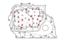
| 4T80E
MH1 Case Cover Bolt Removal |
To
remove the valve body with the channel plate, remove all of the attached
bolts except the bolts indicated by an X (fig.
15).
- Thanks to Darryl Butler |
figure
15
|
| return
to Table of Contents |
|
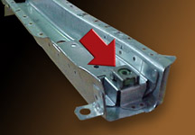
| Rear
Suspension Caged Nuts |
This
information applies to Chevrolet Malibu, Maxx and Equinox, Saturn
Vue and LS, and Pontiac G6 models.
The caged nuts that provide attachment for the rear suspension system
(fig. 16) have a potential for coming out of the cage when removing the
front or rear suspensioin mounting bolts.
TIP: A similar configuration is also used for the engine cradle attaching
nuts.
When the attaching bolt is removed, the nut is free to escape the cage
(fig. 17). This may happen if the vehicle is jostled or moved, as could
occur during collision repair.
TIP: To prevent the nuts from dislodging, put the bolts back into the
nuts as soon as the suspension is lowered away from the bottom of the
vehicle.
If the nut does become dislodged, the only way to get it back into place
is to make a three-sided cut in the floorpan above the nut location and
roll the metal back for access. It will then be necessary to weld and
seal the floorpan.
TIP: If a replacement underbody member is purchased, the nut is temporarily
suspended in the cage by deformable retainers (fig.
18). The first time
the bolt is installed and tightened, the nut is drawn out of the retainers
(fig. 19). If the bolt is later removed, the nut is loose within the
cage, as described above.
-
Thanks to Gregg Potvin |
figure
16
|
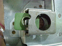
figure
17
|
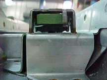
figure
18
|
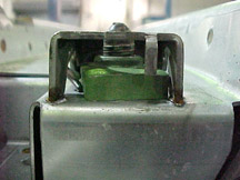
figure
19
|
| return
to Table of Contents |
|
| Malibu
or Classic? |
There
is some misunderstanding about which vehicle is a Malibu. Some technicians
have been looking up the wrong vehicle in SI, and then thinking the
service information is incorrect.
In model year 2004 there are two vehicles thought of as Malibu. The “old” Malibu
(N Body) (fig. 20) was called Malibu through model year 2003. It is
now called Classic in 2004.
The “new” Malibu (Z Body) (fig. 21) is called Malibu
in 2004.
- Thanks to John Oppenlander
“Old” Malibu
(N body) |
“New” Malibu
(Z body) |
through 2003, called Malibu |
|
beginning 2004, called Classic |
new for 2004, called Malibu |
|
figure
20
|
figure
21
|
|
return
to Table of Contents |
|
| Proper
Jump Starting Procedure |
This
information applies to the 2004-05 Pontiac GTO.
Burnt-out headlamp bulbs may result from incorrect jump-starting of the
vehicle, especially if the battery is at an extremely low state of charge
(less than 3 volts).
After starting, if the jumper cables are disconnected too quickly, the
generator creates a momentary voltage spike until the regulator is able
to adjust to the new load condition.
When jump-starting, ensure that both vehicles run for at least one minute
before disconnecting the jumper cables. This allows the battery voltage
to stabilize and avoid any spike in the voltage.
-
Thanks to Art Spong |
|
|
| return
to Table of Contents |
|
| Fuel
Sender/Pump Module Seal |
Be
sure to use the correct part on the 2004-05 Chevrolet Malibu and
Maxx and 2005 Pontiac G6.
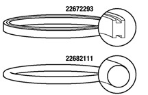
The Malibu Sedan uses a seal with an H cross section, GM p/n 22672293
(fig. 22). The Malibu Maxx and the Pontiac G6 use a seal with an O cross
section, GM p/n 22682111.
TIP: These seals do not interchange.
-
Thanks to David Macgillis |
figure
22
|
| return
to Table of Contents |
|
| GM
Vehicle Care Odor Eliminator |
GM’s
Vehicle Care Odor Eliminator (p/n 12378554) (Canada 88901678) continues
to be your best defense for controlling odors, reducing comebacks
from dampness odors on water leak repairs, and controlling warranty
expense.
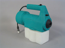
Now, a specially calibrated mini-fogger (fig.
23) is available for rapid
and cost-effective applications to both vehicles and facility areas.
The mini-fogger speeds the application of the solution and allows much
deeper penetration into fabrics, assuring positive results while using
the minimum amount of product. The mini-fogger can be ordered at 1.800.955.8591
in the US (1.800.977.4145 in Canada).
TIP: GM Odor Eliminator permanently eradicates odors after the source
has been eliminated. This product is not a fungicide and will not clean
or control mold and mildew.
-
Thanks to Alan Srodawa |
figure
23
|
| return
to Table of Contents |
|
| 2005
Aveo A/C System |
For
2004, the base-level Chevrolet Aveo was not available with A/C. For
2005, the base-level model can be upgraded with a dealer-installed manual A/C system
(fig. 24). To expedite this installation, all base-level
Aveos are equipped with factory-installed A/C prep equipment. The
accompanying table shows the content differences between the 2004
and 2005 vehicles.
TIP: Only cars with RPO C59 can be upgraded using the dealer installed
kit, p/n 96430552. Installation instructions are included in the kit.
TIP: A 2004 C46 Aveo cannot be upgraded to a 2005 C59 configuration.
The A/C kit is not compatible with the 2004 C46 equipped Aveo.
-
Thanks to John Bowman and Jeff Strausser
|
2004 Aveo |
2005 Aveo |
2004-05 Aveo |
RPO Code |
C46 |
C59 |
C60 |
Option Description |
Heater Only |
A/C Prep |
Manual A/C |
Radiator (480 mm) |
X |
- |
- |
Radiator (600 mm) |
- |
X |
X |
Cooling Fan (single) |
X |
- |
- |
Cooling Fan (double) |
- |
X |
X |
HVAC Module |
- |
X |
X |
A/C Switch |
- |
X |
X |
Wiring Harness Provision for A/C |
- |
X |
X |
A/C Kit (factory installed) |
- |
- |
X |
A/C Kit (dealer installed) |
- |
X |
- |
|
figure
24
|
| |
| return
to Table of Contents |
|
| Abnormal
Noise And Vibration While Driving |
Some
owners of 2005 and prior passenger cars and light duty trucks may
notice an abnormal noise or vibration in their vehicle that may not
have been there when the vehicle was new. Comparison of the customer’s
vehicle with another vehicle of the same make and model may reveal
that the customer's vehicle has a higher level of noise or vibration.
The first step in diagnosis is to evaluate the customer’s vehicle
for aftermarket accessories. The mounting and location of these items
are designed for convenience. Many times they do not take into consideration
the negative effects they may have with air flow over and around the
vehicle, and noise transfer paths when the item is located between
two isolated components.
One known example is the popular step bars (nerf bars) that touch both
the frame of the truck and the cab without any type of insulation.
This accessory becomes the transfer path of normally operating drivetrain
noise into the passenger area of the vehicle.
Other known contributors to noise and vibrations are running boards,
bug shields, sun visors, emergency lights, etc. Removal of these items,
while perhaps not popular with the customer, is necessary in order
to evaluate whether they contribute to the customer's concern.
-
Thanks to Rusty Sampsel
|
| |
| return
to Table of Contents |
|
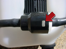
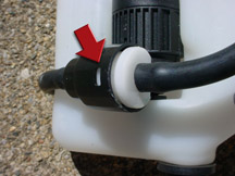
| Windshield
Washer Fluid Leak |
On
some 2005 Chevrolet Equinox vehicles, windshield washer fluid may
leak from the windshield washer pump assembly.
Before replacing the complete windshield washer bottle and washer pump
assembly, inspect the washer pump. Remove the washer fluid bottle and
inspect the pump and check valve attached to the bottle.
The right hand cover of the check valve (white plastic) snaps into
the pump body, and also contains the connection for the windshield
washer hose. Notice that there is a snap molded into the white cover.
When fully assembled, the white snap should be visible through the
opening in the black pump body (fig. 25). If the white plastic cover
is not fully seated (fig. 26), use a pair of pliers to help snap the
cover onto the pump body.
TIP: There should be an audible click sound when the cover snaps into
the pump body. If there is no audible click sound, replace the washer
fluid pump.
TIP: If the washer fluid pump or the reservoir needs to be replaced,
they can be serviced as separate parts.
-
Thanks to Ron Erman
|
figure
25
|
figure
26
|
| return
to Table of Contents |
|
| Roof
Door Module |
On
the 2005 Chevrolet SSR, code U1016 is set as current or history in
the Roof Door Module (RDM), after replacing the RDM with part number
15134308. The part number 15134308 is for the 2003 and 2004 SSR and
is not interchangeable with the 2005 model year.
For the 2005 SSR, the correct part number for the RDM is 15227942.
-
Thanks to Ron Erman
|
| |
| return
to Table of Contents |
|
| Class
2 Diagnostic Tip |
This
information applies to all GM vehicles Using Class 2 communication.
DTC U1000 or U1255 may set current or history, with or without other
DTCs.
These DTCs set when the control module does not receive a message that
it was expecting from another control module, and does not know which
control module did not send the message.
1. If the DTC U1000 or U1255 is set in history with other DTCs set
current or history, diagnose the other DTCs first.
2. If the DTC U1000 or U1255 is set current, this usually indicates
a module that is currently not communicating or a configuration issue.
For example, if the control module is configured for an option (i.e.,
OnStar, keyless entry, memory mirrors, etc.) that the vehicle does
not have, it may expect to receive a message regarding this missing
feature. This would usually occur due to the control module being recently
replaced and incorrectly set up.
3. When the DTC U1000 or U1255 is current, the module that is not communicating
may not even be listed on the Tech 2 on the Diagnostic Circuit Check
/Class 2 Message Monitor list.
4. If the DTC U1000 or U1255 has set in history without other DTCs,
replacing the control module that set the DTC is most likely NOT the
solution.The module that has set the code is looking for an input from
another module that is not communicating. Because the module did not
receive an input that it is expecting to see, it sets a U1000 or U1255
which indicates there was a loss of communications. Look at the customer's
concern (i.e., intermittent, erratic tachometer operation). This will
probably be a better indication of the control module that is the source
of the concern.
-
Thanks to Ron Erman
|
| |
| return
to Table of Contents |
|
 Car Issues
– Fix It Right The First Time Car Issues
– Fix It Right The First Time |
Model
Year(s) |
Vehicle
Line(s) --
Condition |
Do
This |
Don’t
Do This |
Reference
Information / Bulletin |
1997-2005 |
Buick
Century, Regal – Broken
Armrest Lid Latch |
Replace
lid latch only. |
Don’t
replace console armrest lid or front seat center storage armrest
when only latch is needed. |
03-08-49-018A |
2004-2005 |
Grand
Prix – Outside Rearview Mirrors |
Replace
mirror glass or motor, whichever is defective. |
Don’t
replace complete mirror assembly. |
04-08-64-009 |
2004 |
Grand
Prix – Steering, Suspension or Cradle Click Noise |
Re-torque
right steering gear mount. |
Don’t
replace steering gear or cradle. |
03-02-32-048 |
2000-2003 |
Century,
Regal, Lumina, Impala, Monte Carlo, Grand Prix, Intrigue with
3.8L L36 Engine – Coolant Leak |
Replace
upper intake manifold gasket only. |
Don’t
replace upper intake manifold assembly for coolant leak condition. |
03-06-01-016 |
2001-2004 |
Aztek
(01-04), Rendezvous (FWD, 02-04), Venture/Montana/Silhouette
(01-04) – Pop and/or Rattle in Exhaust Down Pipe |
Follow
procedure in bulletin using clamp P/N on down pipe to correct
rattle/buzz noise. |
Don’t
replace converter assembly for rattle/buzz noise without completing
instructions in bulletin. |
03-06-05-003 |
2000-2004 |
All
Cars with 4T40/4T45E and 4T65E – Light On/Various Transmission
Codes Stored |
Check
transmission 20-way connector for secure connection (disconnect
and reconnect). |
Don’t
replace transmission, TCC PWM, VSS, PCS or valve body. |
02-07-30-022B |
1998-2004 |
Seville
– Heated Seat Inoperative |
Replace
only needed heating element. |
Don’t
replace entire seat cover if heated seat element is inoperative. |
01-08-50-002C |
2000-2004 |
Cavalier/Sunfire/Alero/Grand
Am – Inoperative Sunroof Module |
Retime
module or replace only motor for inoperative complaints. |
Don’t
replace entire sunroof module assembly. |
03-08-67-009A |
2003-2004 |
Cavalier/Sunfire
– Air Conditioning Compressor Noisy |
Inspect
for ground out conditions that can cause A/C compressor noise
complaints. |
Don’t
replace A/C compressor for excessive noise complaint without inspecting
for ground outs. |
03-01-38-012 |
1999-2004 |
All
Cars and Trucks – Brake Warranty, Service and Procedures |
Issue
One: Refinish
brake rotor.
Issue Two: Measure for LROs for multiple years.
|
Issue One: Don’t replace brake rotors.
Issue Two: Don’t measure for LRO.
|
00-05-22-002D |
|
| return
to Table of Contents |
|
|
 Truck
Issues – Fix It Right The First Time (new
issues in bold) Truck
Issues – Fix It Right The First Time (new
issues in bold)
|
Model
Year(s) |
Vehicle
Line(s) --
Condition |
Do
This |
Don’t
Do This |
Reference
Information / Bulletin |
2004 |
Tahoe,
Suburban, Silverado, Yukon, Yukon XL, Sierra, Escalade,
Escalade EXT, Escalade ESV, H2 – Passenger Door
Module and RKE Inoperative |
Re-flash
passenger door module. |
Don’t
replace passenger door module. |
04-08-52-005 |
2002-2004 |
Chevrolet
Silverado, GMC Sierra – Accumulator/Accumulator
Bracket |
Replace
accumulator and/or accumulator bracket. |
Don’t
replace compressor. |
02-01-38-007C |
2001-2003 |
Fullsize Pickups – Injector Replacement for High Flow Rates |
Use
Corporate Bulletin Number 04-06-04-007A for injectors with
high fuel return rates. Use Special Policy 04039 for all
01-02 vehicles. |
Don’t
replace 8 injectors for any complaint other than high fuel
return rates. All other injector failures are fix as failed. |
Special
Policy 04039 |
2004-2005 |
All
Cars and Trucks – State-of-Charge Upon Delivery of a
New Vehicle |
Check
battery’s state-of-charge per revised PDI procedure using
Midtronics Conductance Tester. |
Don’t
remove and replace the battery. |
02-06-03-009A |
2002-2004 |
Fullsize and Midsize Pickups and Utilities – Labor Operation
Assignments for Control Module Reprogramming |
When
submitting claims for reprogramming an electronic module, use
correct labor operation that reflects module being programmed. |
Do
not use K5364, which is for reprogramming transmission control
module (TCM), when reprogramming TCCM. |
02-04-21-006D
02-06-04-057D |
2002-2004 |
Fullsize
and Midsize Pickups and Utilities – Sleepy New Venture
Gear Transfer Case Control Module |
Verify
sleepy module as primary cause. Reprogram TCCM with latest
software released 3/11/04. |
Don’t
replace encoder motor or transfer case. Replace the module
only if a C0550 DTC shows as current or in history. |
|
| 2002-2003 |
Chevrolet
Avalanche and Cadillac Escalade EXT – Cargo Covers and
Cladding Faded or Stained |
Thoroughly
clean, dry and treat the components with “Armor-dillo.” |
Don’t
replace cargo covers for this condition. |
04-08-111-001A |
| 2002-2004 |
All
Passenger Cars and Trucks – Air Conditioner Compressor
Diagnosis |
Follow
SI and bulletin for diagnostic information before compressor
replacement. |
Don’t
replace air conditioning compressor. |
01-01-38-013A
03-01-38-019 |
| 2002-2004 |
All
TrailBlazers, Envoy, Envoy XL, Bravada – Squeak/Rub/Scrub
Type Noise in Steering Column |
Lubricate
and remove material, per bulletin. |
Don’t
replace upper or lower intermediate shaft. |
02-02-35-006A |
2001-2004 |
Fullsize
Pickups and Utilities – Servicing Wide Load Mirrors (RPO
DPF) |
Replace
individual parts as needed. |
Don’t
replace complete mirror assembly. |
03-08-64-028 |
|
| return
to Table of Contents |
|
|
| Know-How
Broadcasts for December |
| |
 |
| Know-How
Broadcasts for December |
| 10280.12
Emerging Issues |
December
9, 2004, 9:00 AM, 12:30 PM, and 3:00 PM Eastern Time |
| New
Model Features and Technology Close-Up seminars |
Stay
tuned! These programs will return soon. Check the Service
Know-How section of the GM Training website (www.gmtraining.com)
for more details. |
| -
Thanks to Tracy Timmerman |
|
|
| return
to Table of Contents |
|
|
