| |
| |
Note: Click a picture or illustration in the left column to view a large version in the article.
To hide the large version, simply click on it.
|
|
Revised Brake Bleeding Procedures |
The brake bleeding procedure in SI has been revised for the 2006 Impala and Monte Carlo. Refer to document 1700002 for details.
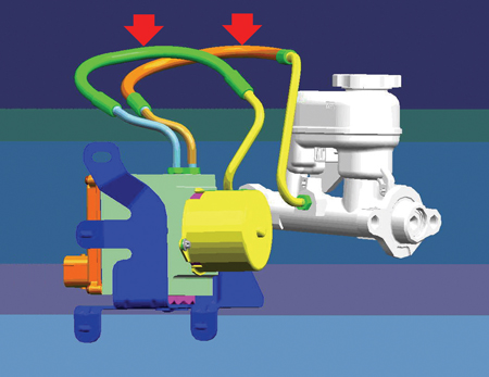
In the brake lines between the master cylinder and the ABS module, there is a point at which the brake line is routed higher than the master cylinder reservoir (fig. 1). If air gets into this line, due to a disconnected component, it will rise to the high point in the line and care must be taken to purge all of it from the lines.
The revised procedure assists in doing this. Here are the highlights of the new procedure.
First, use pressure bleeder J-29532-A.
Second, carefully loosen the fittings on the lines between the master cylinder and the ABS module just enough to be able to rotate the lines temporarily below the level of the reservoir, then tighten the fittings.
TIP: There is a flexible portion in each of these lines, which makes repositioning possible.
Third, perform the bleeding procedure. During this time, you will bleed the left front/right rear diagonal pair of wheel cylinders. Then the right front/left rear diagonal pair of wheel cylinders. This increases fluid flow, to assist in purging air from the lines.
Fourth, when the bleeding procedure is complete, carefully loosen the fittings on the lines repositioned earlier. Move them back to their original positions and retighten.
IMPORTANT: Loosen the fittings just enough to allow the lines to move, not enough to allow air to enter.
- Thanks to Rob Coultes
|

figure 1 |
return
to Table of Contents |
|
|
| Shared 5-Volt Reference Circut |
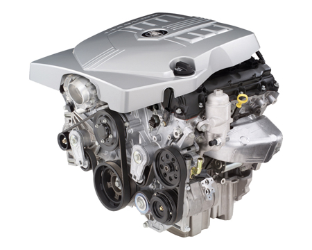
This information applies to 2004-06 Cadillac CTS and SRX and Buick Rendezvous and 2005-06 Cadillac STS and Buick LaCrosse/Allure equipped with the LY7 3.6L V-6 and LP1 2.8L V-6 engines (fig. 2).
The engine control module on these engines is not equipped with a 5-volt reference diagnostic trouble code (DTC).
The components listed below share the 5-volt reference A circuit.
- Mass Air Flow/Intake Air Temperature (MAF/IAT) Sensor
- Barometric Pressure (BARO) Sensor
- Engine Oil Pressure (EOP) Sensor
- Throttle Position (TP) Sensor
- Accelerator Pedal Position (APP) Sensor
- A/C Refrigerant Pressure Sensor
- Fuel Tank Pressure (FTP) Sensor
If an open, short to ground, or short to voltage exists in the shared 5-volt reference A circuit, it is likely that DTC P0102 -- MAF Sensor Circuit Low Voltage will be the only DTC to set. This is because the MAF sensor circuit diagnostic is the first to run after the open, shorted to ground, or short to voltage occurs.
TIP: If there is a condition with the 5-volt reference circuit, be sure to test all the shared circuits and components.
Be sure to refer to the Engine Data Sensors -- 5-Volt Reference(s) Bus schematic in SI when diagnosing DTCs involving the listed components.
- Thanks to Dave Dickey
|

figure 2 |
| return
to Table of Contents |
|
| Diesel Engine Cover |
On the G-Van, the bottom side of the engine cover is lined with insulating material. For 2006 with the diesel engine, several engine components are close to the insulation when the cover is in place: turbo variable pitch vane sensor, Fuel Operated Heater (FOH) coolant pipe clamps, and the Glow Plug Module heat shield.
The insulation can be ripped if the cover is carelessly handled (fig. 3).
To avoid damage to the insulator, use care when removing the cover. But take even greater care when installing the cover. Keep it level. Do not force it into place or strike it with your hand to seat it.
- Thanks to Jack Cady and Mathew Gray
|
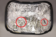
figure 3 |
|
return to
Table of Contents |
|
Top Tier Gasoline Update |
MFA Oil Company, Kwik Trip/Kwik Star and The Somerset Refinery, Inc. have been added to the list of gasoline brands the meet the TOP TIER Detergent Gasoline Standards (bulletin 04-06-04-047E). Canadian dealers should refer to bulletin 05-06-04-022.
These brands have been added to the running list in the Reference Guide on the TechLink website.
- Thanks to Jay Dankovich |
return
to Table of Contents |
|
| Equinox Oil Level |
There’s been a change to the engine oil fill specification for the 2005-06 Chevrolet Equinox with 3.4L V-6 engine. The engine oil capacity with filter is listed in the 2005-06 Chevrolet Equinox owner’s manual as 4.5 quarts (4.3 L). This is being revised to an initial fill of approximately 4.0 quarts (3.8 L) with filter, followed by a top-off as necessary.
TIP: The 4.5 quart (4.3 L) recommendation was an initial volume fill for a completely dry engine at the assembly plant.
- Thanks to Ken Peacock and the Service Department at Bill Abbott GM, Monticello, IL |
return
to Table of Contents
|
|
Powertrain Cooling Component Survey |
Denso, supplier of STS, SRX, and CTS powertrain cooling components (fig. 4) (radiators, clamps, hoses, lines) is looking for your help. Please help us increase customer satisfaction by improving our products.
If you fill out the survey at http://www.surveymk.com/denso you will be eligible to win one of ten $50 Home Depot gift cards. If you're interested, please complete the survey by December 31, 2005.
- Thanks to Dan Kosmowsk
|

figure 4 |
|
return to Table of
Contents |
|
| Z06 Corvette Oil Pan Drain Plugs |
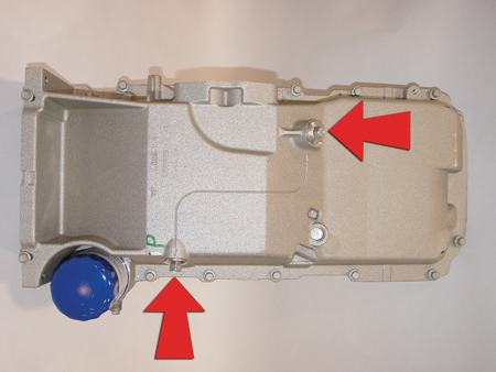
The August 2005 issue of TechLink contained imprecise information about changing engine oil in the Corvette Z06.
After draining the oil from both drain plug locations, you should “Reinstall both oil drain plugs and tighten to 25 Nm (18 lb ft).” (fig. 5)
TIP: It is NOT necessary to install replacement plugs
|

figure 5 |
| return
to Table of Contents |
|
|
Checking Front Suspension Z Height |
One of the required preliminary measurements before performing a front end alignment is checking the front suspension Z height. This height setting is critical for proper camber settings as well as overall vehicle ride height.
TIP: In addition to alignment issues, extremely incorrect Z height can contribute to a third order wheel tire vibration on vehicles equipped with front drive axles.
In Trim Height Inspection Procedures, SI provides a specification from the center of one of the lower control arm attaching bolts to an imaginary plane extending from the bottom edge of the lower ball joint.
Here’s a method of measuring this dimension. It will give accurate results using a 4 foot (1.2 m) carpenter’s level and a tape measure.
Prepare the vehicle:
- Sitting on an alignment rack
- Suspension fully supporting the vehicle
- Pins out of the pivot pads
- Tire pressure adjusted to certification label specification
- Doors, hood, trunk all closed
- Full tank of fuel
Jounce the front and rear suspension to obtain at least 1.5-inch (3.8 cm) deflection and allow the vehicle to settle.
Set the top edge of the level on the reference surface of the lower ball joint (A) and extend the level directly under the appropriate control arm attachment bolt. While keeping the level in contact with the ball joint reference surface, adjust the level up/down until the bubble indicates it is horizontally level. Then extend the tape measure straight down from the center of the attachment bolt (B). The point where the tape measure and level intersect is your measurement (fig. 6).
Repeat the jounce/measure process 3 times and average the readings. The average is your final measurement.
TIP: It may be necessary to cut a notch approximately 3 inches long by 1 1/2-inch deep (7.6 cm by 3.8 cm) in one end of the level to clear the wheel rim and still maintain contact with the level working surface against the ball joint reference surface.
- Thanks to Ken Peacock, North Central Regional Service Engineer
|
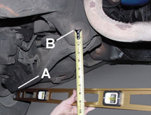
figure 6
|
| return
to Table of Contents |
|
| Reset Transmission Adaptive Pressure Values |
Many GM vehicles with automatic transmissions have a feature called Transmission Adaptive Pressure (TAP). Updating TAP information is a learning function of the PCM or TCM designed to maintain acceptable shift times. It is recommended that TAP information be reset when the following repairs have been made:
- Transmission overhaul or replacement
- Repair or replacement of an apply or release component (clutch, band, piston, servo)
- Repair or replacement of a component or assembly which directly affects line pressure
TIP: Resetting TAP values with a scan tool erases all learned values in all cells. So, the PCM or TCM needs to relearn TAP values. Learning new TAPs may affect transmission performance.
Some vehicles require doing more than using a scan tool to reset TAP. Do a bulletin search first to see if additional steps are required. Refer to bulletin 01-07-30-018 for 2002 midsize utilities with 4L60-E.
SI service manual on-vehicle procedures have been updated to remind you to reset TAP values.
- Thanks to Jerry Garfield
|
| return
to Table of Contents |
|
Security System — Inclination Sensor |
An inclination sensor accessory kit is now available for 2003-06 C/K trucks and Hummer H2.
The inclination sensor detects changes in the parked angle of the vehicle. If a change is detected (0.3° for 7 seconds), the vehicle’s content theft alarm is sounded.
TIP: The sensor re-baselines itself continuously, which allows it to account for parking on steep grades, as well as slow tire leaks, without unintentional activation.
Although the sensor is principally intended to detect unauthorized jacking (such as stealing a wheel and tire) or unauthorized towing, it may also be set off by other factors:
- Loading or unloading the vehicle
- Unstable loads
- Person or large pet in vehicle
- Parking on unstable surface, such as ferry boat.
TIP: There are provisions for locking the vehicle without activating the alarm when this is desirable.
One kit p/n 17801364 is available. The kit includes an instruction sheet, the inclination sensor, wiring harness, Owners Manual insert, and related hardware for installation.
Programming
IMPORTANT: The kit may be installed only on a vehicle that is equipped with keyless entry option AU0.
IMPORTANT: The instruction sheet contains an authorization code. You must use this code, plus the vehicle’s VIN, when contacting TCSC to obtain a BCM VCI (Vehicle Configuration Index) number. The VCI number is good for only the VIN for which it is issued.
TIP: TCSC can be reached at 1.888.337.1010. For added efficiency, make just one phone call to TCSC if installing wheels and inclination sensor on the same vehicle.
IMPORTANT: Be sure you are using the latest version of Tech 2 and TIS software.
Follow the instruction sheet procedure to program the vehicle before installing the sensor. Observe the conditions and precautions in the instruction sheet to avoid damage to the control module.
Installation
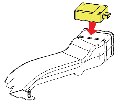
Follow the instructions to install the sensor. Connect the supplied wiring to the sensor, the BCM and the I/P body relay block. The sensor is attached to the top surface of the HVAC left floor duct (fig. 7), using the adhesive pad on the sensor. Test the sensor, following the instruction sheet procedure.
Be sure to provide the Owner Manual insert to the owner after completing the installation.
- Thanks to Sharon Folts and Joyce Henk |
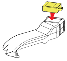
figure 7 |
|
return to Table of
Contents |
|
|
New Diagnostic Approach for General Motors Vehicles |
In the early 1980s, technicians were being asked to diagnose electronically controlled engines. At the time, the majority of these technicians had little or no electrical training and needed all the assistance the service information could give them. This assistance was supplied in a very structured step by step electrical testing method.
Today, 25 years later, technicians have been through electrical/electronic training and understand how to test control modules, circuits, and components. Despite this, diagnostics are still written in the structured format. General Motors realizes technicians today have much more electronic training and are capable of diagnosing the most difficult vehicle electrical systems. Because of this, General Motors is enhancing the electrical diagnostic service information for today’s technicians.
This new diagnostic approach offers
- more information
- fewer words
- better formats
- fewer pages to print.
The diagnostics are now written so you can use your knowledge and experience to decide the quickest method to repair the vehicle. Areas with the biggest changes include the addition of the Diagnostic Fault Information and the restructuring of the diagnostic table information. The diagnostic table no longer exists, but has been broken into three new diagnostic categories:
- Circuit/System Verification
- Circuit/System Testing
- Component Testing.
The new format does not force you to any of the three diagnostic categories. However, starting with the Circuit/System Verification category will help you determine if a vehicle condition is current. Your experience will determine the best approach to diagnose and repair the vehicle. If history has shown a number of parts failing in a particular area, you may choose to perform a component test first. In some cases, the part may be OK, so you will then choose the Circuit/System Verification or Circuit/System Testing category to continue diagnosis.
DIAGNOSTIC CATEGORIES
In the following paragraphs, new titles and information are indicated by an asterisk (*) and blue type.
The following describes all the possible diagnostic categories which may be included in diagnostic procedures.
DTC Descriptor
Describes what DTCs are diagnosed in this procedure. The DTC number (with Symptom Description when applicable) and descriptor are written out.
Diagnostic Fault Information*
A link to the Diagnostic System Check – Vehicle, in case you bypassed it, is provided here.
The diagnostic Fault Information table identifies each circuit that makes up an electrical subsystem and the associated circuit failure modes. DTCs and symptoms are listed in the table for all circuit failure modes. This information can be used by itself to diagnose an electrical fault, or as a quick visual showing how the different symptoms and DTCs apply for the subsystem being diagnosed.
Circuits |
Short to Ground |
Open/High Resistance |
Short to Voltage |
Signal
Performance |
ECT Sensor Signal |
P0117 |
P0118 |
P0118 |
P0125
P0128 |
ECT Low Reference |
— |
P0118 |
P0118 |
P0125
P0128 |
Typical Scan Tool Data*
A table showing a scan tool data parameter value in reference to circuit failure modes
ECT Sensor Temperature – PCM
Circuits |
Short to Ground |
Open |
Short to Voltage |
Operating Conditions: Engine Running
Parameter Normal Range: −32°C (−26°F) to +130°C (+275°F) |
ECT Signal |
−40°C (−40°F) |
140°C (284°F) |
−40°C (−40°F) |
Low Reference |
— |
−40°C (−40°F) |
−40°C (−40°F) # |
# Internal ECM damage may occur if shorted to B+ |
Circuit/System Description
This identifies how a circuit/system normally functions.
Conditions for Running the DTC
This identifies what conditions must be present to allow the diagnostic to run.
Conditions for Setting the DTC
This identifies the condition(s) that must be present in order to fail the software diagnostic and when to set the DTC.
Actions Taken When DTC Sets
This identifies the default actions taken when a control module sets a DTC.
Conditions for Clearing the DTC
This identifies the conditions that must be present in order to clear the DTC.
Diagnostic Aids
These are suggestions which explain other methods to diagnose the condition. It also provides unique information about the system used to assist you in finding and repairing a vehicle condition.
Reference Information*:
Links providing additional information for the diagnostic procedure are located here.
For example:
- Schematic Reference
- Connector End View Reference
- Description and Operation
- Electrical Information Reference
- DTC Type Reference (for Powertrain DTCs)
- Scan Tool Reference
- Special Tools Required
Circuit/System Verification*
A non-intrusive description outlining how to verify that a system or a portion of a system is functioning correctly. During the verification process, the vehicle is kept intact and tested as a complete system. This verification is used to assist you in locating a current or an intermittent condition. You should be able to identify if the failure is occurring on the input circuit (signal) or on the output circuit (control) when applicable. You will need to decide from the verification results if the system is working properly or if further diagnosis needs to be performed (Circuit/System Testing or Component Testing).
Circuit/System Testing
This category replaces the current diagnostic table in a different format. A positive step by step testing sequence is used in place of the diagnostic table, which allows you to perform each step in sequence until a fault is detected. If the result of a test step is achieved, the normal flow is to proceed to the next step. If the result is not achieved, the arrow bullet identifies what action needs to take place. You will no longer have to answer a diagnostic question with yes or no in order to determine which path in a diagnostic table to follow.
Intrusive diagnostics are performed to locate the actual system failure. System harness connections are disconnected from the module or component to test individual circuit functions. The electronic control module or component will be used to assist in validating the circuit functions. When a test does not pass, the repair step(s) will indicate what circuit failures need to be tested (short to voltage, short to ground or open/high resistance). The control module and component(s) will also be diagnosed during these test steps.
Component Testing*
This category will offer, when applicable, a static and/or dynamic component test. These tests can be used to verify if a component is not operating properly to avoid unnecessary replacement.
If the component cannot be tested in a static or dynamic way, an output control using a scan tool can be specified. The harness and controller will need to be verified as good before using an output control to validate the component.
Testing control modules in this category will not be offered, as they would require very expensive special tools. In most diagnostics, the control module is used to verify the harness circuits in the Circuit/System Testing category and a retest of the control module should always be performed before replacement.
Repair Instructions*
A link to Diagnostic Repair Verification is provided here. This link describes how to verify the vehicle is repaired.
All links to Repair or Replacement (R&R) procedures are located here.
Repair Verification*
This category will be used only when the Diagnostic Repair Verification procedure (in Repair Instructions) does not adequately verify the repair. A unique verification procedure will be provided to support the diagnostic repair.
- Thanks to Dave Nowak
|
|
return to Table of
Contents |
|
| Service Manual Goes Global |
Part 2
Reminder - the Service Manual is going global. No longer are there different service manual styles and layouts for various GM regions around the world.
Last month we explained how service information is being organized according to a new Global Table of Contents. And we promised you a look at it this month. Here it is. The first column shows the previous table of contents, with grey shading indicating first level categories that have been replaced. The second column shows the new Global Table of Contents, with orange indicating first level categories that have been added. And the third column shows some new second level categories that are included under Roof and Seats.
TIP: To help you envision the complete new structure, check out the Global Table of Contents display under the Reference Guide tab of the TechLink website.
Most of the changes occur in the Body and Accessories first level categories and their accompanying second level categories.
The other first level categories did not need much change. Here is a summary of some of the major changes:
- All of the Engine Controls X.XL sections were re-named to Engine Controls and Fuel X.XL.
- Cruise Control has moved to Engine from Accessories.
- Power Take-Off has moved from Accessories to Transmission/Transaxle
- All of the Transfer Cases were moved to Transmission/Transaxle from Driveline/Axle.
- Two level two categories within Restraints have been moved to new level one category Safety and Security
Some second level categories (like Doors, Seats, and Roof) were getting too large, making it cumbersome to find the correct information. When North America started working with the rest of the globe to create a Global Table of Contents, we saw this as an opportunity to reorganize some of the larger service categories into smaller, more manageable chunks. Some examples are shown in the third column of the table.
- Thanks to Peter Bowen
Previous Table of Contents
First Level Categories |
|
Global Table of Contents
First Level Categories |
|
Global Table of Contents
Second Level Categories
(typical examples) |
|
|
|
|
|
Preface |
|
Preface |
|
|
General Information |
|
General Information |
|
|
Accessories |
|
Body Hardware and Trim |
|
|
|
Body |
|
Body Repair |
|
|
|
|
Body Systems |
|
|
Brakes |
|
Brakes |
|
|
|
|
Diagnostic Navigation |
|
|
|
|
Driveline/Axle |
|
|
|
|
Driver Information and Entertainment |
|
|
|
Engine |
|
Engine |
|
Folding Top |
HVAC |
|
HVAC |
|
Luggage Rack and
Roof Trim |
Restraints |
|
Hybrid |
|
|
|
Power and Signal Distribution |
|
Moveable Roof |
Removable Top |
|
|
Roof |
<- |
Sunroof |
|
|
Safety and Security |
|
|
|
|
Seats |
<- |
Power Seats |
Steering |
|
Steering |
|
Seat Hardware, Trim
and Upholstery |
Suspension |
|
Suspension |
|
Transmission/Transaxle |
|
Transmission/Transaxle |
|
Seat Heating and Cooling |
Vehicle Control Systems |
|
|
|
|
Replaced Categories |
|
Added Categories |
|
|
return to Table of
Contents |
|
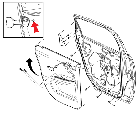
| Door Trim Panel Screw |
On the front (fig. 8) and rear (fig. 9) doors of the 2006 Impala, there is a screw hidden behind the reflector at the rear edge of the trim panel. Remove the reflector for access to the screw. The door panel will be damaged during removal if this screw is not first removed.
This information was recently added to documents 1599149 and 1599150 in SI.
- Thanks to Jerry Garfield
|
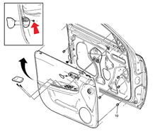
figure 8 |
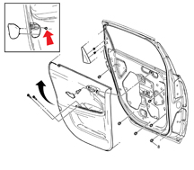
figure 9 |
| return
to Table of Contents |
|
| Windows Won’t Close |
This information applies to 2005-06 Cadillac DeVille and DTS.
On some vehicles, the front windows will not close. While moving to the closed position, the window will raise approximately 2/3 of the way up, then goes into express down.
TIP: Do not replace the window regulator.
Remove the door trim. Raise the window off the bottom-of-travel position. Loosen the window-to-regulator retainers (2) at the bottom of the glass. Grasp both sides of the glass and pull it to the full rearward position in the rear glass run channel. This assures that the glass is in full contact with the run channel. Secure the lower regulator retainers and cycle test to verify the repair. Re-assemble the trim to the door.
- Thanks to Joe Allen |
| return
to Table of Contents |
|
| Diagnostic Trouble Codes Shared in Multiple Modules |
For 2005-06, some control modules (ECMs, TCMs) used in GM passenger cars and light duty trucks have specific diagnostic trouble codes that describe internal failures of the module. These DTCs are not module-specific and can be found on any controller that has these codes.
Society of Automotive Engineering (SAE) J2012 committee has set these specific codes to be an industry standard of all manufacturers.
At present, these common codes are:
P0601 |
Control Module Read Only Memory (ROM) |
Transmission Control Module (TCM) Read Only Memory (ROM) |
P0602 |
Control Module Not Programmed |
Transmission Control Module (TCM) Not Programmed |
P0603 |
Control Module Long Term Memory Reset |
Transmission Control Module (TCM) Long Term Memory Reset |
P0604 |
Control Module Random Access Memory (RAM) |
Transmission Control Module (TCM) Random Access Memory (RAM) |
P1621 |
Control Module Long Term Memory Performance |
Transmission Control Module (TCM) Long Term Memory Performance |
IMPORTANT: Use caution when diagnosing these shared codes, to perform the appropriate diagnostic procedure on the appropriate module.
Refer to the appropriate Service Information (SI) document for Diagnosis and Repair procedures.
- Thanks to Darryl Butler
|
| return
to Table of Contents |
|
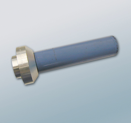
| Axle Pinion Seal Installer |
Recently, Kent-Moore has made a change to two axle pinion seal installers.
Tool J-24384, the 10.5-inch Axle Pinion Seal Installer and J-36366, the 8.25-inch Axle Pinion Seal Installer, were changed from molded plastic to machined aluminum. The tools were changed to improve quality and durability.
When using either of these new installers, the J-5590 Pinion Bearing Installer needs to be attached to install the seal (fig. 10).
The tools are currently available from SPX/Kent-Moore.
- Thanks to Lance Mossman and Michael Clark
|

figure 10 |
| return
to Table of Contents |
|
| Headlamp Defeat Feature |
After the replacement of the BCM on a 2002 vehicle, the headlamp defeat feature becomes inoperative. Below is a revised summary of the operation of the defeat feature on 2002-06 Buick Rainier, Chevrolet Trailblazer, GMC Envoy and Oldsmobile Bravada.
TIP: This information does not apply to vehicles sold in Canada.
1. On 2002 models with the original BCM, the automatic headlamp/DRL disable feature can be activated by applying the parking brake before turning the ignition on or by pressing the interior light defeat switch in 4 times. Either method will disable the headlights and DRLs until the parking brake is released (park brake method) or until the ignition is cycled or the defeat switch is pressed again 4 more times (defeat switch).
TIP: The vehicle should not be driven with the parking brake applied to disable the headlights or DRLs. The park brake feature is intended for use during a parked situation only.
2. On 2002 models were the BCM was replaced, the automatic headlamp disable feature can be activated by pressing the interior light defeat switch in 4 times. This disables the exterior lights and requires manual operation of the headlamps for the entire key cycle.
TIP: This will disable the lights for that key cycle only.
3. On all 2003-06 models, there is an OFF feature on the headlamp switch. Rotate the headlamp switch to the left one time to disable and a second time to enable the automatic light feature. The lights will default to the on position at each key cycle.
- Thanks to Dino Poulos |
| return
to Table of Contents |
|
| Suction Cup Marks on Rear Window |
There have been reports of suction cup marks appearing on the outside of the rear window of some 2006 Chevrolet Impalas (fig. 11). The marks are most noticeable when there is moisture on the rear window.
The marks are caused by the machine that installs the rear window glass. The machine's suction cups may leave a trace amount of silicone, causing the marks on the outside of the rear window.
To remove the marks, use a window cleaner that contains ammonia. It may require several applications to clean the marks.
- Thanks to Dennis Kosmowski
|

figure 11 |
| return
to Table of Contents |
|
| Fuse Open — Underhood Accessory Wiring Junction Block |
This information applies to Buick Rainier, Chevrolet TrailBlazer, GMC Envoys and Saab 97x between 2004 and 2006. Some of these vehicles may exhibit ABS and SES lights on, with DTCs C0055 and B0540 stored, and speedometer inoperative.
The condition may be due to fuse 53 (15A TRANS) in the Underhood Accessory Wiring Junction Block found to be open. This fuse provides ignition 1 voltage to the ECM and Transmission Shift Solenoids. The only symptoms will be SES light, ABS light, speedometer inoperative and the EBCM will have no VSS using the Tech 2. ECM and TCM will show the correct VSS value using the Tech 2.
Inspect fuse 53 in the Junction Block for an open. If fuse 53 is open, replace the fuse and inspect circuit 139 from the Junction Block to the TCM and Transmission for a short to ground. Refer to SI document 1454646 for the schematic.
- Thanks to Dino Poulos |
| |
| return
to Table of Contents |
|
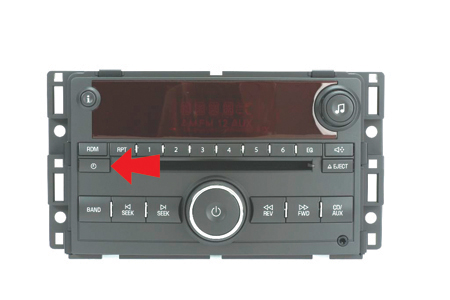
| Setting the Time on New Radio |
This information applies to the new radio on the 2006 Chevrolet Impala.
TIP: To set the time on this radio, the power must be on.
Standard Radio (fig. 12)
Press the clock button and the HR, MIN, MM, DD, YYYY (hour, minute, month, day, and year) will appear on the display. Press the pushbutton located beneath any one of the labels that you want to change. Each time the button is pressed, the selected element will increase by one.
TIP: The selected time and date may be increased by pressing the right SEEK arrow or FWD button. To decrease, press the left SEEK arrow or REV button.
TIP: The selected setting can also be adjusted using the radio tune knob.
With Six-Disc CD Player (fig. 13)
On vehicles with a six-disc CD player, the radio has a MENU button instead of the clock button. Press the MENU button until the clock option is displayed. Then press the pushbutton located under that label. The HR, MIN, MM, DD, YYYY will appear on the display. To change the time or date, follow the instructions given above.
12/24 Hour Setting
To change the time default setting from 12 hour to 24 hour or to change the date default setting from month/day/year to day/month/year, press the clock button. Then the press the button located under the forward arrow label. Once the time 12H and 24H, and the date MM/DD/YYYY (month, day, and year) and DD/MM/YYYY (day, month, and year) are displayed, press the button located under the desired option. Press the clock or MENU button again to apply the selected default, or let the screen time out.
- Thanks to Dennis Kosmowski
|
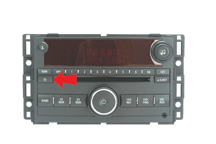
figure 12 |
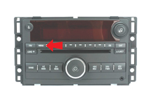
figure 13 |
| return
to Table of Contents |
|
 Car Issues
— Fix It Right the First Time (new issues in bold) Car Issues
— Fix It Right the First Time (new issues in bold) |
Model Year(s) |
Vehicle Line(s) / Condition |
Do This |
Don’t Do This |
Reference Information/Bulletin |
2005-2006 |
Uplander, Terraza, Relay, Montana SV6 – High Effort to Sound Horn, Horn Sounds Only When Certain Spots are Pressed |
Replace horn pad springs. |
Don’t replace inflatable restraint steering wheel module. |
05-08-54-001 |
2005 |
Grand Prix, LaCrosse, Allure – Front Brake Moan and/or Groan Noise During Brake Apply |
Confirm that noise is coming from front brakes – then replace front brake pads. |
Don’t resurface the front rotors. |
05-05-23-006 |
2004-2005 |
Grand Prix, LaCrosse, Allure – Blower Motor Inoperative or Intermittent, Blower Speed May Drop or Blower Continues to Run After Key Off |
Install 330MFD capacitor between LPM circuit and ground. |
Don’t replace the LPM, blower motor or HVAC control head. |
05-01-39-001A |
2002-2005 |
Buick LeSabre – Front Door Window Binds/Inoperative/Moves Slowly |
Adjust glass. |
Don’t replace the window regulator. |
05-08-64-011 |
2002-2007 |
Cavalier, Sunfire, Grand Am, Classic – Vehicle Hesitates, No Start, Lack of Power, Low Fuel Pressure |
Replace fuel pump strainer. |
Don’t replace the fuel pump module. |
05-06-04-026A |
2001-2003 |
Aztek, Rendezvous – Window Regulators Separate from Window Motors |
Use window regulator clips and procedure outlined in bulletin instead of replacing complete window regulator assemblies. |
Don’t replace window regulator assemblies that are serviceable and only have broken clips. |
03-08-64-015 |
1999-2004 |
All Cars and Trucks – Brake Warranty, Service and Procedures |
Issue One: Refinish brake rotor.
Issue Two: Measure for LROfor multiple years. |
Issue One: Don’t replace the brake rotors.
Issue Two: Don’t measure for LRO |
00-05-22-002D |
2002-2005 |
Cars and Trucks – Multiple Driveability Symptoms/Clogged Fuel Injectors |
Clean fuel injectors as described in Bulletin. |
Don’t replace fuel injectors. |
03-06-04-030A |
|
| return
to Table of Contents |
|
|
 Truck Issues — Fix It Right the
First Time (new issues in bold)
Truck Issues — Fix It Right the
First Time (new issues in bold)
|
Model Year(s) |
Vehicle Line(s) / Condition |
Do This |
Don’t Do This |
Reference Information/Bulletin |
2003-2005 |
Tahoe, Yukon, Escalade – Engine Vibration/Noise at Idle, Vibration Felt in Steering Wheel/Seat |
Reprogram PCM. |
Don’t align exhaust and/or hang weights. |
05-06-01-006 |
2002-2004 |
All TrailBlazers, All Envoys, Rainier, Bravada – Underhood Tick Noise at Idle |
Reprogram PCM. |
Don’t replace electro-viscous fan clutch. |
05-06-02-004 |
2004 |
Full Size Pickups and Utilities, H2 – Passenger Door Module and RKE Inoperative |
Re-flash passenger door module. |
Don’t replace passenger door module. |
04-08-52-005 |
2001-2005 |
Full Size Pickups and Utilities – Cranks But No Start, Stall, Inaccurate/Incorrect Fuel Gauge Reading, No Fuel, Vehicle is Out of Fuel and Fuel Gauge Reads Above Empty |
Replace fuel sensor. |
Don’t replace fuel sender module. |
04-08-49-018E |
2005 |
HUMMER H2 SUT/SUV – Momentary Loss of HVAC Blower Motor Operation While Adjusting Power Seats |
Install 330 mf 50V capacitor. |
Don’t replace HVAC control head, blower motor or seat switches. |
05-01-39-004 |
2001-2005 |
Chevrolet/GMC 36 Series Cab/Chassis – DTC P1172 or P2636, Fuel Gauge Reads Empty, SES Light On |
Modify fuel tank balance line. |
Don’t replace fuel tank unit, PCM or fuel transfer pump. |
05-06-04-008 |
2002-2005 |
Tahoe, Suburban, All Yukons, All Escalades, Avalanche, H2 – Exhaust Pop/Ping Noise |
Replace heat shield. |
Don’t replace exhaust system. |
03-06-05-008B |
2004-2005 |
All Cars and Trucks – State-of-Charge Upon Delivery of a New Vehicle |
Check battery’s state-of-charge using J-42000 or J-42000-EU. |
Don’t remove and replace battery. |
02-06-03-009A |
2002-2004 |
Silverado, Suburban, Tahoe, Sierra, Yukon/XL, Escalade EXT – Rough Idle, Misfire, MIL DTC P0300 |
Measure intake manifold for warpage across two runner ports only. Replace upper manifold gasket with teal-green color gasket. |
Don’t measure intake manifold for warpage across all four intake runner ports. Don’t replace upper intake manifold gasket with orange-colored gaskets. |
05-06-04-029 |
2001-2003 |
Fullsize Pickups – Injector Replacement for High Flow Rates |
Use Corporate Bulletin Number 04-06-04-007A for injectors with high fuel return rates. Use Special Policy 04039 for all 01-02 vehicles.
P/Ns: 97729095 |
Don’t replace 8 injectors for any complaint other than high fuel return rates. All other injector failures are fix as failed. |
Special Policy 04039 |
|
| return
to Table of Contents |
|
|
|
Know-How Broadcasts for
DECEMBER |
| |
 |
| Know-How
Broadcasts for DECEMBER |
|
10290.12D Emerging Issues |
December 8, 2005
9:30 AM and 12:30 PM Eastern Time
|
|
New
Model Features |
For Web NMF courses, log on to the GM Training Website (www.gmtraining.com). Select Service Know-How from the menu, then choose New Model Features for a selection of courses. |
| -
Thanks to Tracy Rozman |
|
|
return
to Table of Contents |
|