Table
of Contents – October 2002 |
|
|
|
|
|
|
|
|
|
|
|
|
|
|
|
|
|
|
|
|
|
 |
Note: Clicking
on any picture or illustration will open a larger version of that art.
|
|
Wheel
and Tire Balancing |
Consider a Chevrolet
TrailBlazer travelling at 60 miles per hour. The P245/70R16 tires have
a diameter of 29.6 inches. At 60 miles per hour, they're running 703
rpm. If a tire is out of balance, at that speed it introduces 703 vibrations
per minute into the vehicle. The tire is slapping the pavement 12 times
per second (12 Hz). You think the customer is going to notice that?
Actually, tire related shake or vibration is one of the most common
customer dissatisfiers, and it's most easily noticed when driving on
a smooth highway. There are three causes: out-of-round, imbalance, and
radial force variation (RFV). Each one of these conditions can result
in shake or vibration, but the causes and cures are different for each.
They are not necessarily related, but each of them must be addressed.
Here's where to find guidance in SI:
- "build"
the vehicle
- General Information
- Vibration Diagnosis
and Correction
- Diagnostic Information
and Procedures
- Vibration Analysis
-- Tire and Wheel
The Vibration Analysis
chart contains thorough test procedures. The exact path you will follow
depends on what you find on the vehicle you're diagnosing, but in general,
you will check in this order: runout, imbalance, and RVF.
Runout (Out-of-Round)
TIP:
It's
tempting to start with wheel balance, but it's important to measure
on-vehicle runout first. If runout is the cause of the vibration, balancing
won't fix it. But removing the wheel/tire assembly to check balance
can disturb runout evidence. This is because a small amount of runout
in the wheel may cancel or accentuate a small amount of runout in the
mounting surface, depending on which position the wheel is mounted.
This is referred to "stack-up" of runout.
Wheel/tire runout is measured two ways, on-vehicle and off-vehicle.
The on-vehicle measurement includes possible runout of not only the
wheel and tire but also the mating hub/axle flange and studs. Off-vehicle
runout measures only the wheel and tire assembly. Further, it may be
necessary to measure runout of just the wheel, with the tire dismounted.
The diagnostic chart explains how to interpret and correct various runout
conditions you detect.
One of the repair methods is called match-mounting (vectoring). This
procedure permits you to move the tire on the wheel to determine if
the low and high spots cancel each other out. In a similar fashion,
it may be possible to match-mount the wheel to the mounting flange.
See SI for details.
Imbalance
Wheel/tire balance is fairly easy to
understand, and of all the conditions mentioned here, offers the most
visible evidence. The weights are there for everyone to see. However,
if runout or RFV is the cause of the vibration, checking balance is
not going to fix the condition.
That having been said, there is an appropriate time to check and correct
wheel/tire balance, according to the diagnostic chart.
TIP: Be sure
to check for foreign materials, particularly inside the wheels, and
particularly when the vehicle has been driven in snowy, icy or offroad
conditions. Correcting an imbalance condition may be as simple as removing
a chunk of mud.
The readily available off-vehicle, two-plane dynamic balancer is the
equipment of choice for checking and correcting imbalance.
As with any precision tool, proper calibration, proper maintenance,
and proper use are all important in obtaining satisfactory results.
Radial
Force Variation
Radial force variation (RFV) refers to variations within the construction
of the tire. All tires have splices in the various plies. These resulting
stiffer spots do not cause problems unless they are excessive.
The causes of radial force variation are impossible to see, so RFV is
the least understood cause of vibration.
TIP: RFV can
masquerade as excess runout or imbalance. RFV can cause vibrations even
though the wheel/tire assembly has acceptable runout and is properly
balanced. If you've eliminated these two conditions, RFV is your likely
culprit.
TIP: The Vibration
Analysis chart in SI contains a link to an Isolation Test, which can
help you identify which wheel/tire assembly is the source of the vibration.
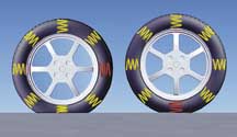
As you can see in figure 1, it's helpful
to think of the tire's sidewall as a series of coil springs. If one
of the "springs" is considerably stiffer than the others,
the tire will bump each time that portion contacts the pavement. This
will be perceived as a vibration.
RFV is measured by specialized equipment in which the mounted tire is
pressed against a load wheel. The load simulates the weight of the vehicle.
As the tire is rotated, the equipment measures the variations in the
tire's radial force.
Most vehicles will tolerate these RFV values:
P-metric
tires
on passenger cars |
18
lbs (8.1 kg)
or less |
P-metric
tires
on light trucks |
24
lbs (10.8 kg)
or less |
LT
tires
on light trucks |
30
lbs (13.5 kg)
or less |
TIP:
Technical
Assistance has information on tire parameters that may deviate from
these guidelines.
Correcting radial force variation is similar to correcting for runout.
The stiffest part of the tire is matched up with the lowest part of
the wheel.
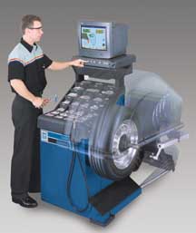
Hunter GSP9700
The Hunter GSP9700 Vibration Control System (figure
2) is now available from GM Dealer Equipment (1.800.GMTOOLS).
A major benefit of the GSP9700 is that a single piece of equipment can:
- measure off-vehicle
runout
- check and correct
balance
- check and correct
radial force variation
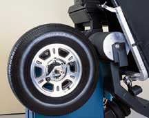
The tire, spinning
at 90 rpm, is contacted by a load roller (figure
3). The roller's radial position is affected by the varying stiffness
of the tire as it rotates. While the tire rotates 4 revolutions, sensors
take 128 readings per revolution.
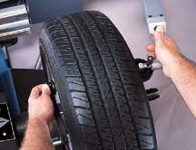
Inner and outer Dataset® arms equipped with sensors measure the
wheel's runout (figure 4).
TIP: There is
a high correlation between inside and outside measurements on most wheels.
In cases where external measurements cannot be made, the tire must be
removed to measure the inside dimensions of the bead seat.
By combining the data from the roller and Dataset sensors, the GSP9700
can calculate vectoring and weight requirements. There is even a feature
which determines where to place weights so they don't show on spoked
wheels.
Important
When mounting a GM wheel to a balancing machine, always
use the center pilot hole with a back cone. Use a flange plate to clamp
the wheel to the cone and machine.
Any type of service equipment that removes tread rubber by grinding,
buffing or truing is NOT recommended, and may void the tire warranty.
Tires may have been ground by the tire company as part of the manufacturing
process, and this is a legitimate procedure.
- Thanks to Dave Scribner at Hunter Equipment, and to Russ Dobson |
|
figure
1
|
figure
2 |
figure
3 |
figure
4 |
| return
to Table of Contents |
| |
| Valve
Index Balancing

|
This applies to
trucks with 16 and 19 1/2 inch hub-centric offset dual wheels. The term
hub-centric means that the wheel is oriented to the vehicle by means
of the hub hole in the wheel, not by the mounting studs and nuts.
The procedure ensures that the wheel is mounted to the balancer and
to the vehicle using the same location method.
TIP: The adapter
and backing plate used to align the hub of the wheel to the balancer
are relatively new, and are available by calling 1.800.GMTOOLS (1.800.468.6657).
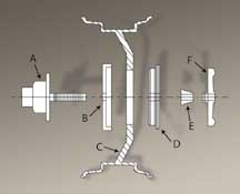
Mount the wheel on the balancer using the parts shown in figure
5.
A - Balancer Faceplate
B - Backing Plate
C - Wheel
D - Adapter
E - Cone, Used as Spacer
F - Nut
Rotate the wheel/tire assembly until the valve is at 12 o'clock. Loosen
the nut. If the hub hole in the wheel does not fit the adapter snugly,
the wheel will drop slightly and "hang" on the adapter, with
the valve at 12 o'clock position. Then tighten the nut to secure the
wheel to the balancer.
Balance the wheel/tire assembly in the usual manner.
With the vehicle raised, mount the wheel/tire to the vehicle with the
valve and the hub pilot tab at 12 o'clock position. Again, if the hub
hole does not fit the mounting flange snugly, the wheel will drop slightly
and "hang" on the tab. Then, tighten the wheel nuts to secure
the wheel.
IMPORTANT: Rotate
the wheel to place the valve at 6 o'clock.
Lower the vehicle and torque the wheel nuts to specification.
- Thanks to Tom Bussard at Hennessy Industries,
Inc. |
figure
5 |
| return
to Table of Contents |
|
| Class
2 Corner Tip of the Month |
Dynamic
menu building is a technique by which the Tech 2 will poll the Class 2
bus to find out what controllers are installed on the vehicle before it
builds the menu choices to display. For instance, when Body is selected
from the Powertrain/Body/Chassis selection menu, the Tech 2 will first
inquire about what body related controllers are installed and build the
menu accordingly. This is a more efficient use of the Tech 2's resources,
but can cause problems for you when diagnosing a Class 2 related problem.
For example, if a 2001 Suburban has a BCM related fault and you select
Body on the Tech 2, the menu selections displayed by the Tech 2 may be
erroneous because the BCM was unable to respond properly when the Tech
2 polled the bus. One indication that this has happened is that when you
select the BCM, the Tech 2 displays only DTC Info. When you select DTC
Info, you end up at the Class 2 DTC Check, which is under the Diagnostic
Circuit Check.
The Tech 2 provides a Bypass Mode which can be enabled under Tool Options
from the main menu. This will allow you to select the combinations manually.
Try playing with the Bypass Mode before you need it, to be familiar with
the feature.
- Thanks to Mark Harris |
| return
to Table of Contents |
|
| Know-How
Broadcasts for November |
| |
 |
| Know-How
Broadcasts for November |
Emerging
Issues |
November
14 |
9:00
AM, 12:30 PM,
3:30 PM
Eastern Time |
Technology
Close-Up |
November
21 |
9:00
AM, 12:30 PM,
3:30 PM
Eastern Time |
| -
Thanks to Tracy Timmerman |
|
|
| return
to Table of Contents |
|
| New
Airbag Features in 2003 Full-Size Pickup Trucks |
Supplemental
Inflatable Restraint (SIR) technology is moving to another level of sophistication
in the 2003 C/K trucks.
TIP: The
dual-stage inflator module feature and the instrument panel disable switch
continue to be used.
There are three interrelated parts to the new SIR system:
- Passenger Presence
System
- Seat Belt Tension
Retractor Sensor
- Seat Position
Switch
Here's a brief explanation
of each. You can find additional information in SI:
- "build"
the vehicle
- Restraints
- SIR
- Description
and Operation
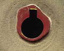
Passenger
Presence System (PPS)
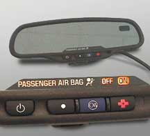
The only readily visible evidence of a change is the
inclusion of a new telltale in the rearview mirror (figure
6). It reads either PASSENGER AIR BAG ON or PASSENGER AIR BAG
OFF.
A Passenger Presence System (PPS) sensor in the passenger seat detects
the size of the passenger, based on weight. If the passenger does not
exceed the PPS weight threshold, the instrument panel (I/P) airbag is
disabled. In the event of an accident, the I/P airbag does not deploy.
Also, if the front passenger seat is empty, the I/P airbag will not
deploy.
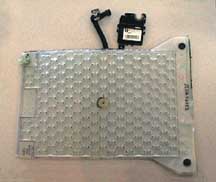
The PPS sensor consists of a gel-filled bag (figure
7) mounted beneath the seat cusion foam, which operates an electrical
pressure sensor. The pressure sensor converts the pressure from the
occupant to an electrical signal and sends the signal to the PPS module.
PPS Diagnostics
The PPS module monitors itself for faults. The PPS module
communicates with the SDM to turn on the AIRBAG indicator in the instrument
cluster when a fault is present. When a Tech 2 is used, the PPS module
will flash DTCs using the rear view mirror indicators.
PPS Service
IMPORTANT:
The PPS is a calibrated unit. When replacing the assembly, all parts
in the service kit must remain together. Do not mix any of the old parts
with the new parts. After repairing or replacing the PPS, the system
must be rezeroed in order to function correctly.
See SI for details.
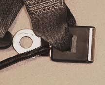
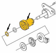
Seat Belt Tension Retractor Sensor
The second addition to the SIR system is the Seat Belt
Tension Retractor Sensor (figure 8), which
enhances the PPS when an infant seat is properly restrained on the front
outboard passenger seat.
When an infant seat is properly restrained, the seat belt is tightly
secured. This pulls on the tension retractor sensor in the lower seat
belt anchor. The PPS module uses this information, along with a signal
from the PPS sensor in the seat, to determine if the I/P airbag should
be enabled or suppressed.
Seat Belt Tension Retractor Sensor Diagnosis
If a fault is detected, the PPS module sets a DTC 023.
The code may be flashed by the rear view mirror indicator, using the
Tech 2.
Seat Position Switch
And third, a seat position switch (SPS) is used to determine
how close a front seat occupant is to the frontal airbag. In the event
of an airbag deployment, the SPS determines whether to enable or disable
Stage 2 deployment. There is an SPS for each front seat, and each SPS
affects only the airbag on the side of the vehicle where the SPS is
located.
The SPS consists of a Hall-effect switch, mounted to the seat track
(figure 9). The Hall-effect switch divides
the seat travel into two parts: seat forward or seat rearward.
In the seat rearward position, Stage 2 deployment is enabled. In the
seat forward position, Stage 2 deployment is disabled, and only Stage
1 is permitted.
TIP: The SPS
is secondary to the PPS status. And the SPS and PPS are secondary to
the manual I/P disable switch. If the manual I/P disable switch is in
the disable mode, the passenger airbag will not deploy, regardless of
SPS or PPS status.
SPS Diagnosis
The SDM monitors the SPS circuit, and if a fault is detected,
the SDM will set codes B0083 or B0084. And the SDM defaults to disabling
Stage 2 frontal deployment.
Airbag Deployment Summary
In the event of an accident, the airbag SDM deploys the
frontal airbags in response to inputs from the deployment sensors.
The SDM uses information from the seat position sensors to determine
whether to enable or disable Stage 2 deployment. The driver side and
passenger side are treated separately.
In addition, passenger frontal airbag deployment will be suppressed
by any of the following:
- manual I/P disable
switch turned to the disable position
- weight on the
passenger seat below the PPS threshold
- presence of
an infant seat, as detected by PPS and passenger seat belt tension
retractor sensor.
-
Thanks to Chuck Wieseckel |
figure
6 |
figure
7 |
figure
8 |
figure
9 |
| return
to Table of Contents |
|
| Multi-port
Flexible Injection System (MFI) |
Last
October, we introduced you to a new MFI fuel system on 2002 Chevrolet
Astro and GMC Safari Vans and 2002 Silverado and Sierra pickups equipped
with the LU3 V6 engine and YF5 California emissions package.
Now that you've had a chance to view this system and possibly service
it, here are some reminders about this new fuel system.
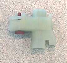
The injector at the end of the fuel tube is a Multec 2 injector. This
is the same injector that is used on most passenger cars. In this case,
it's attached to a fuel tube and a fuel meter body rather than a fuel
rail.
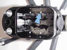
It is possible to differentiate the new Multi-port Flexible injection
from the earlier generation SCPI system by simply removing the manifold
injector connector and looking inside the cavity. Both the SCPI and the
MFI have two electrical pins visible inside the cavity.
TIP: You
can also look at the VIN number which for this engine is X.
On the SCPI system, between the two electrical pins is a small black hole,
used to remove the injector from the fuel meter body with a small screwdriver
(figure 10).
On the MFI system, between the two electrical pins is a small white post
in a hole. This is where you push with a screwdriver to remove the injector.
The white plastic tip added to the end of the fuel tube is a retainer
used to hold the fuel tube securely in place with the injector spray pointed
toward the intake port (figure 11). This
tip also moves the injector further away from the heat of combustion which
actually protects the injector from building up deposits on the tip. Moving
the injector further from the heat and vapors formed inside the intake
manifold keeps the injector very clean.
TIP: As with any
other Multec 2, cleaning of this system is not recommended by the manufacturer.
Remember that MFI and SCPI systems are similar in appearance but different
when it comes to servicing the system.
- Thanks to Dan Wimer |
figure
10 |
figure
11 |
| return
to Table of Contents |
|
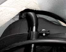
| Pontiac
Vibe EVAP System |
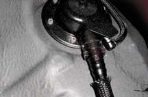
This
condition can affect All Wheel Drive Pontiac Vibes. With the check engine
light illuminated, there may be DTCs P0440, P0441, P0442 and P0446. The
codes refer to a condition with the EVAP system, most often with the fuel
tank vent hose connection at the ORVR valve. The valve is located at the
top right corner of the fuel tank.
First connect the Evaporative Emissions System Tester J-41413-200 to the
underhood EVAP service port. The port can be identified by the green cap
covering the port.
TIP: At
first, leave the gas cap untouched to verify that the customer didn't
leave the gas cap loose.
When the tester starts to force smoke through the EVAP system, you will
notice smoke leaving the EVAP canister vent hose. This is normal. Pinch
off the vent hose before looking for signs of a leak. If smoke is found
to be leaking from the top right front corner of the fuel tank, the plastic
quick disconnect vent hose may either be partially disconnected or there
is too much of a strain at the connection between the ORVR valve and the
vent hose (figure 12).
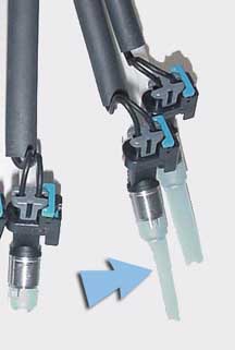
To resolve the concern without dropping the fuel tank, grasp the plastic
vent hose close to the top of the tank and push towards the ORVR valve.
If the hose was partially disconnected, you will hear a click.
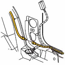
Retest the system with the EVAP system tester. If you still see smoke,
rotate the vent hose toward the center of the vehicle. Remove the vent
hose from the side of the fuel tank. Grasp the hose at the top of the
tank and gently move the hose toward the middle of the vehicle. You should
only have to move the valve slightly to correct the leak (figure
13).
Retest the system for leaks. When the leak is corrected, you will no longer
notice smoke leaving the EVAP system. Make sure you clear the DTCs before
returning the vehicle to the customer.
- Thanks to Jeff Strausser |
figure
12 |
figure
13 |
| return
to Table of Contents |
|
| Powertrain
Quality Center Update |
A
new Powertrain Quality Center (PQC) was implemented July 1 to obtain faster
and more accurate quality information on all replaced assemblies (August
2002 TechLink).
This information and more is included in a new bulletin 02-07-30-029A
issued in September.
TIP: Before replacing
an OEM engine or transmission, service assembly or over-the-counter assembly,
be sure to follow instructions in bulletin 02-07-30-029A.
The new bulletin explains which engine and transmission assemblies are
involved, how to obtain pre-approval, and how to submit warranty claims.
It also includes a two-page template which acts as a guide to the information
required by PQC for pre-approval of warranty engine assemblies.
TIP: Fill out a
copy of this template before calling PQC, to expedite the phone call and
avoid callbacks.
- Thanks to Jim Colyer |
| return
to Table of Contents |
|
| |
Owners
of some 2002 Oldsmobile Alero and Pontiac Grand Am models may comment
about poor radio reception. This condition may be caused by a poor antenna
co-ax connection at the passenger side lower kick panel (area in front
of door, under the instrument panel). To correct this condition, remove
the lower kick panel (figure 14), re-connect
the antenna co-ax and tape the connection securely to avoid any future
disconnection.
- Thanks to Ray Romeo |
figure
14 |
| return
to Table of Contents |
|
| Visor
Contacts Inside Mirror |
Owners
of some 2000-03 Buick Century or Regal models may comment that the visor
contacts the rear view mirror when moving the visor downward. This condition
may be more likely with the OnStar® mirror.
This condition, which may caused by the inside rear view mirror being
placed in a higher position during the assembly process, is easily correctable.
The mirror has a ball pivot on the windshield side (toward front of vehicle)
and a ball pivot on the mirror side (toward rear of vehicle). The rear
ball pivot must be moved downward. This places the mirror assembly lower
on the windshield, allowing clearance between the visors and mirror. Minor
adjustment may be necessary, right or left.
After completing the previous process to center the mirror between the
sun visors, adjustment for rear vision is made using the ball socket on
the mirror side.
TIP: This same
procedure may be used to remedy comments about being able to see the roof-mounted
console in the rear view mirror on some vehicles.
- Thanks to Wayne Zigler |
| return
to Table of Contents |
|
| Sunshade
Removal Tips |
The
new style 2002 -2003 S/T GMC Envoy, Chevrolet TrailBlazer, Oldsmobile
Bravada, GMC Envoy XL and Chevrolet TrailBlazer EXT vehicles are all equipped
with a tab-retaining sunshade system that attaches to the roof sheet metal.
Sunshade Removal Procedure
The sunshade can be removed without degradation to the retaining system
or to the roof sheet metal by following the removal procedure in the GM
service manual.
This is the recommended service manual method for removing the sunshade
.
- Remove the windshield
garnish molding.
- Release the
front assist handle from the headliner.
- Recline the
bucket seat and release the upper portion of the center pillar trim
panel.
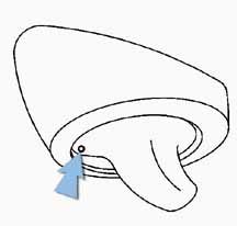
- Open and rotate
the sunshade parallel to the side window.
- Insert a small
tool into the bezel access hole (figure 15).
IMPORTANT:
Midway through the rotation cycle the tool will move further into the
access hole.
- Push upward
on the tool while rotating the sunshade parallel to the windshield.
The sunshade pivot arm bezel should appear to be recessed into the
bezel.
IMPORTANT:
Ensure the pivot arm is recessed into the bezel before removing the
sunshade from the headliner.
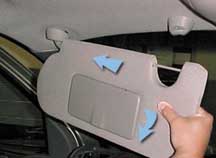
- Apply outbound
pressure to the sunshade while the sunshade is parallel to the windshield
(figure 16).
- Pull the sunshade
downward while maintaining outbound pressure to the sunshade. You
will notice a separation between the headliner and the sunshade bezel.
- In order to
remove the sunshade from the headliner, carefully grab the headliner
at the windshield pillar area and apply downward pressure while gently
rocking the sunshade up and down.
- Remove the inboard
retainer screw.
- Remove the inboard
retainer from the headliner.
- If equipped
with lighted sunshades, perform the following:
- Reach above
the headliner to access the electrical connector.
- Remove the electrical
connector from the headliner substrate.
- Disconnect the
sunshade electrical connector from the headliner harness.
- Remove the sunshade
from the vehicle.
Roof Sheet
Metal Inspection
Following the recommended removal method in sequence
will ensure the integrity to the roof sheet metal. In the event the
sunshade was removed before reviewing the service manual, inspect the
roof sheet metal for any potential degradation and straighten the effected
areas before installing the sunshade (figure 17).
Installation
Refer to the GM Service Manual for the installation procedure
of the sunshade and inboard retainer, and the torque specifications
to the inboard retaining screw.
- Thanks to Jim Clower and Andy Slawick |
figure
15 |
figure
16 |
figure
17 |
| return
to Table of Contents |
|
| Steering
Clunk Noise |
Owners
of some 1998-2002 Cadillac Sevilles may comment about a clunking or rattling
noise heard while travelling over bumps. The sound comes from the lower
steering column, and may be caused by the clearance between the steering
shaft and lower steering column shaft bearing.
A new bearing 26100500 and retainer 07847029 have been released to address
this condition. Figure 18 shows the retainer
on the left and the bearing on the right.
TIP: The retainer
is used on power tilt and telescope columns only.
Refer to bulletin 02-02-35-004 for details.
- Thanks to Bill Denton |
figure
18 |
| return
to Table of Contents |
|
| Blower
Motor Inoperative |
Owners of some 1999-2002
Oldsmobile Alero and Pontiac Grand Am models may comment that the blower
motor is inoperative. If the correction requires resistor replacement,
check the resistor for signs of corrosion. If signs of corrosion are
present, refer to bulletin 01-08-57-003 and verify that the air intake
foam sealing strip is correctly positioned and securely adhered. This
additional step will help prevent repeat occurrences of this issue.
- Thanks to Ray Romeo |
| return
to Table of Contents |
|
| Hose
Clamps Eliminated |
Clamps
have been eliminated from both ends of the radiator overflow hose on mid-year
2002 S/T vehicles. This is not a production error; do not install clamps
under warranty.
- Thanks to Dan Oden |
| return
to Table of Contents |
|
| Radio
Programming |
In
the past few months, GM Service and Parts Operations has fielded a variety
of calls from technicians who have encountered programming issues with
up-level radios which have been swapped from another vehicle.
The following procedures must be followed when swapping up-level radios
for:
- 2003 C/K Trucks
and Sport Utilities
- G and H Vans
- Hummer H2
- C Series Medium
Duty Trucks.
NOTICE:
Failure to do so will cause permanent damage to the
radio.
- First, ensure
that the TIS software is up to date at the Techline client and then
update the Tech 2 accordingly.
- Check the RPO
code of the original radio in the vehicle. If the RPO code of the
radio being installed is the SAME as the RPO code of the original
radio, program as normal.
- If the RPO code
of the radio being installed is DIFFERENT from the RPO code of the
original radio that is being removed or swapped, you must call the
Techline Customer Support Center (TCSC) for a VCI number BEFORE programming
the radio.
US dealers call
1.888.337.1010 (Prompt 3).
Canadian dealers call 1.800.828.6860 (English) or 1.800.503.3222 (French).
If you need assistance with programming, please contact the Techline
Customer Support Center at the number listed above.
- Thanks to Craig Jones and Rich Adkins |
| return
to Table of Contents |
|
| Key
Release Difficulty |
Owners
of some 2003 Cadillac CTS models may experience the inability to remove
the key from the ignition lock cylinder, even though the battery is in
a good state of charge.
This condition may be caused by a misadjusted transmission shift control
linkage. The gate-release button on the shift knob has a micro-switch
which allows the ignition key to be released. The cable adjustment is
crucial to the proper operation of the key. Refer to current document
ID 792993 in SI for the proper shift control linkage adjustment procedure
before proceeding with additional diagnosis.
- Thanks to GM Technical Assistance |
| return
to Table of Contents |
|
| New
Engine Coolant Fill Procedure |
On 2003 G and H
vans with a 4.8, 5.3, or 6.0L Gen III V8 engine, there is a new engine
coolant fill procedure. It is necessary because the engine cooling system
does not use a pressurized coolant surge tank.
After the engine coolant has been drained from the engine, if engine
coolant is added only through the radiator neck and engine coolant overflow
reservoir, the engine coolant may not flow beyond the closed thermostat,
located on the engine at the lower radiator hose connection. Although
the engine coolant level may appear full in the radiator neck, the system
may be 4 to 6 quarts low, and a major engine overheat condition may
occur.
After correcting the reason for the coolant drainage, use the following
procedure to fill the entire engine cooling system to capacity.
Remove the upper radiator hose at the radiator. Remove the half-inch
diameter coolant air bleed hose from the radiator, located 5 inches
below coolant pressure cap.
Slowly fill the cooling system through the upper radiator hose with
coolant mixture until it flows without air bubbles from the coolant
air bleed hose, and coolant level stabilizes in the upper radiator hose.
Install the coolant air bleed hose and the upper radiator hose to the
radiator. Fill the radiator with coolant mixture and install the coolant
pressure cap.
Start and run the engine at 2000-2500 RPM until the engine reaches normal
operating temperature. Then, allow the engine to idle for 3 minutes.
Shut the engine off and allow the engine to cool. Top off the coolant
as necessary in the reserve tank, inspect the concentration of the engine
coolant, rinse away any excess coolant from the engine and the engine
compartment, and inspect the cooling system for leaks.
The written procedures on the GM SI website will be corrected shortly
and a Service Manual Update bulletin will be published.
- Thanks to GM Technical Assistance |
| return
to Table of Contents |
|
| Headlamp
Replacement Due To Moisture |
Owners of some 2000-2003
Chevrolet Malibus may comment on moisture in one or both headlamps.
This may be due to normal atmospheric conditions.
The headlamps on the Malibu are vented, and may exhibit fine condensation
on the inner surface of the lens under certain atmospheric conditions.
This condensation will clear more quickly with the headlamps turned
on or when the vehicle is in motion. It may take up to six hours for
the moisture to clear under these conditions.
Headlamps should not be replaced for fine condensation on the inside
of the lens that clears with operation of the lamps. Headlamps should
be replaced only if:
- there is water
accumulated in the bottom of the lamp
- the moisture
does not clear with operation of the lamps
- comparison with
the lamp on the opposite side of the car indicates a difference in
performance.
TIP:
The black rubber seal around the outside of the lamp is for appearance
only, and does not seal the lamp from moisture.
For more information on evaluating exterior lamps for moisture inside
the lamp, please refer to bulletin 01-08-42-001.
- Thanks to GM Technical Assistance |
| return
to Table of Contents |
|
| Power
Door Lock Programming |
On 2003 Chevrolet
Tahoe, Suburban, Silverado C/K Pickup, and GMC Yukon, Yukon XL, or Sierra
C/K Pickup, customers may have difficulty in programming the automatic
door locks, following the procedure in Section 2 of the owner's manual.
The corrected procedure is located in SI under document number 866362
and can be made available to your customers. These procedures are not
part of the Driver Information Center programming feature found in Section
3 of the owner's manual.
TIP: When cycling
through the lock and unlock modes by using the lock and unlock switches
on the door, count the number of chimes heard after each press of the
switch to determine each lock option.
- Thanks to GM Technical Assistance |
| return
to Table of Contents |
|
| Bulletins
- October, 2002
This review
of service bulletins released through mid-September lists the bulletin
number, superseded bulletin number (if applicable), subject and models. |
00
- General Information
02-00-89-014; New Labor Operation Codes for Dealer-Installed GM Accessories
Replaced During Warranty Coverage Period; 2002 and Prior GM Passenger
Cars and Trucks, 2003 Hummer H2
02-00-89-015; Dealer Installed Regular Production Accessories (RPA);
2003 Buick Rendezvous, Pontiac Aztek
01 - HVAC
02-01-39-004; New PAG Oil Released; 2002 Chevrolet Cavalier, Oldsmobile
Alero, Pontiac Grand Am, Sunfire, with 2.2L Engine (VIN F -- RPO L61),
all 2002 Passenger Cars, Trucks and Hummer H2
03 - Suspension
02-03-09-002; Intermittent Boom, Rumbling Noise and/or Disturbance Heard
in Passenger Compartment While Driving at Highway Speeds (Replace Rear
Coil Springs); 2002 Chevrolet TrailBlazer, GMC Envoy with Rear Coil
Springs
02-03-10-005; Diagnostic Tips for Steering Wheel Shake/Vibration (Oscillation)
Concerns; 2003 Chevrolet Kodiak and GMC Topkick C4500-C5500 Conventional
Cab
05 - Brakes
02-05-25-005; Diagnostic Trouble Code C0201 Set and Stored in History;
2003 Chevrolet Express and GMC Savana 2500/3500 Vans, Chevrolet Silverado
and GMC Sierra 2500/3500HD Pickups with Manual HVAC (RPOs CJ3 or C42)
06 - Engine/Propulsion System
02-06-01-027; Higher Than Expected Oil Consumption; 2002-03 Chevrolet
Silverado and GMC Sierra 2500-3500, 2003 Chevrolet Kodiak and GMC Topkick
C4500-C5500 with 6.6L Duramax(tm) Diesel Engine (VIN1 -- RPO LB7)
02-06-01-028; Engine Crankcase Flush; 2003 and Prior GM Cars and Trucks,
2003 Hummer H2 with Gasoline Engines
02-06-03-008; replaces 43-64-07A; Low Voltage Display on IP Gauge, Lights
Dim at Stop Lights, Battery Discharged, No Start, Slow Cranking, Dim
Lights at Idle, Low Generator Output; 1990-2003 Passenger Cars and LD
Trucks, 2003 Hummer H2
02-06-03-009; Battery Charging Tips; 1990-2003 Passenger Cars and LD
Trucks, 2003 Hummer H2
02-06-04-041; Diagnostic Hints/Troubleshooting Guide for Denso Common
Rail Fuel Systems; 1999-2002 Chevrolet and GMC C-Model MD Tilt Cab,
2000-03 Chevrolet and GMC WT5500 MD Tilt Cab
02-06-04-043; Revised DTC P0340 Camshaft Position Sensor (CMP) Sensor
Circuit Diagnostic; 1996 Chevrolet Astro Van, GMC Safari Van with 4.3L
Engine (VIN W -- RPO L35)
02-06-04-044; Service Engine Soon (SES) Light Illuminated, DTC P0440
Set (Replace Fuel Tank Evaporative Emissions Control System EVAP Vent
Solenoid Harness); 2000-02 Chevrolet Cavalier, Pontiac Sunfire
02-06-04-045; Revised DTC P0327; 2002 Chevrolet Cavalier, Oldsmobile
Alero, Pontiac Grand Am, Sunfire
07 - Transmission/Transaxle
02-07-30-022A; replaces 02-07-30-022; Service Engine Soon (SES) Light
On with DTCs P0716 and/or P0717, P0730, P0753, P0758, P1860, P1887,
or other Miscellaneous Transmission Trouble Codes Set (Repair Wiring
at Transaxle Wiring Pass-thru Connector); specified 2000-03 Passenger
Cars and Vans with 4T65-E, 4T40-E or 4T45-E Transaxle (RPOs MN3, MN7,
M15, M76, MN4, MN5)
02-07-30-025A; replaces 02-07-30-025; Harsh Shifting, Delayed Upshifts,
Possible CHECK TRANS Lamp Illuminated, Possible DTC 21 Stored in TCM
Memory (Follow TPS Relearn Procedure); 1999-2003 Chevrolet and GMC W-Series
MD Tilt Cab Models with Diesel Engine and Aisin Automatic Transmission
02-07-30-030; Transmission 1-2 Shift Shudder, Vibration, Slips, Chuggle
(Install Generator Voltage Sense Circuit); 2001-03 Chevrolet Silverado,
GMC Sierra with 4L60-E Automatic Transmission (RPO M30)
08 - Body and Accessories
01-08-66-005B; replaces 01-08-66-005A; Availability of Pickup Box Reinforcement
Kits for Toolbox/Rear Window Barrier/Ladder Rack Applications; 1999-2003
Chevrolet Silverado and GMC Sierra (New Body Style) Pickups with Steel
Fleetside Pickup Box (RPO E63), Except Dual Rear Wheel (RPO R05), Stepside
(RPO E62) and Inner Composite (RPO E37) Pickup Boxes
01-08-66-014A; replaces 01-08-66-014; Pickup Box Sheet Metal Fracture/Damage
with Aftermarket Accessories Installed (Repair Pickup Box Fracture/Damage
and Install Pickup Box Reinforcements); 1999-2003 Chevrolet Silverado
and GMC Sierra (New Body Style) Pickups with Steel Fleetside Pickup
Box (RPO E63), Except Dual Rear Wheel (RPO R05), Stepside (RPO E62)
and Inner Composite (RPO E37) Pickup Boxes
02-08-44-012; Enable or Disable Remote Keyless Entry (RKE) Radio Personalization
Feature; 2000-02 Chevrolet Cavalier, Malibu, Oldsmobile Alero, Pontiac
Grand Am, Sunfire
02-08-61-003; Side Assist Step Pad Warping (Install New Step Pad Kit);
2001 GMC Sierra C3 Luxury Pickup Models with Uplevel Side Assist Steps
(RPO BVF)
02-08-62-001; Front Fascia Loose (Replace Front Fascia Pencil Braces);
2002 Chevrolet TrailBlazer, GMC Envoy, Oldsmobile Bravada built before
VIN breakpoint
02-08-64-017; No Start, Service Engine Soon Lamp On, ABS Warning Lamp
On, Air Bag Light On, DTCs Set, Various Door Electrical Functions Inoperative
(Replace Driver and/or Passenger Door Harness and/or Repair Body Harness
Connector); 2002 Chevrolet TrailBlazer, GMC Envoy, Oldsmobile Bravada
built before April 2002
02-08-66-005A; Loose or Broken Rear Compartment Opening Molding (Install
New Molding Assembly); 1997-2002 Chevrolet Malibu, 1997-99 Oldsmobile
Cutlass, 1999-2002 Oldsmobile Alero and Pontiac Grand Am
02-08-98-001A; Metal Panel Bonding; 2003 and Prior GM Passenger Cars
and Trucks, 2003 Hummer H2 |
| return
to Table of Contents |
|
|
|
