
| |
||||||||||||||||||||||||||||||||||||||||||||||||||||||||
|
|
||||||||||||||||||||||||||||||||||||||||||||||||||||||||
|
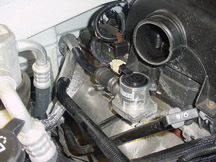
2004 Secondary AIR Injection (AIR) System |
The Secondary AIR
system used in the 2004 TrailBlazer, Envoy, Rainier and Bravada with
the 4.2L in-line 6-cylinder engine incorporates a new AIR pump and an
electronic AIR shut-off valve. - Thanks to Frank Tornambe |
|||||||||||||||||||||||||||||||||||||||||||||||||||||||

figure 1 |
||||||||||||||||||||||||||||||||||||||||||||||||||||||||
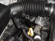 figure 3 |
||||||||||||||||||||||||||||||||||||||||||||||||||||||||
| return to Table of Contents | ||||||||||||||||||||||||||||||||||||||||||||||||||||||||
|
|
||||||||||||||||||||||||||||||||||||||||||||||||||||||||
| What’s
New in Diagnostic/ Special Functions |
A new feature is being phased into the Tech 2, beginning with TIS satellite
version 9.0, Tech 2 software version 23.005, released late in August.
Software version 23.005 must be installed for this feature to work. - Thanks to Mark Stesney |
|||||||||||||||||||||||||||||||||||||||||||||||||||||||
|
||||||||||||||||||||||||||||||||||||||||||||||||||||||||
|
|
||||||||||||||||||||||||||||||||||||||||||||||||||||||||
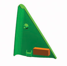
| Right
Front Speaker Rattle |
A
rattle or buzz from the right front speaker on a 2000-04 Sunfire or
Cavalier may be generated by the door trim panel upper extension covering
the exterior mirror mount (commonly known as the shark fin) (fig.
5). Before replacing the speaker, verify that the shark fin is
not the concern. Apply pressure to the shark fin at the forward lower
corner. If the rattle diminishes, repair the concern by removing the
trim panel (refer to SI Document 1043347). Add a foam block to the forward
lower corner to dampen the low frequency vibrations. Install the trim
panel and tighten the screw to 1.3 Nm or 12 lb in. |
|||||||||||||||||||||||||||||||||||||||||||||||||||||||
|
return to Table of Contents |
||||||||||||||||||||||||||||||||||||||||||||||||||||||||
| Starter Cranks After Key is Released -- Reminder | Refer
to bulletin 03-06-03-001. These are the highlights. - Thanks to Jim Mauney and Jay Dankovich |
|||||||||||||||||||||||||||||||||||||||||||||||||||||||
| return to Table of Contents | ||||||||||||||||||||||||||||||||||||||||||||||||||||||||
|
|
||||||||||||||||||||||||||||||||||||||||||||||||||||||||
| Module
Application and Programming for 2004 |
A
number of modules included on cars and trucks need to be configured
to the vehicle when a replacement is installed. A table has been prepared
to cover all cars and light duty trucks for the 2004 Model Year. Go
to the Reference Guide tab. - Thanks to Lindsey Beauchamp |
|||||||||||||||||||||||||||||||||||||||||||||||||||||||
| |
||||||||||||||||||||||||||||||||||||||||||||||||||||||||
| |
||||||||||||||||||||||||||||||||||||||||||||||||||||||||
| Ashtray Repair Spring |
If
a spring breaks on the ashtray of a 2000-04 Buick LeSabre, it’s
not necessary to replace the entire ashtray. - Thanks to Bill Metoyer and Martin Tulashie |
|||||||||||||||||||||||||||||||||||||||||||||||||||||||
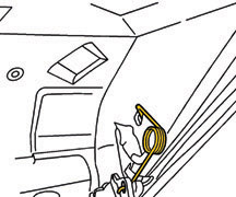 figure 6 |
||||||||||||||||||||||||||||||||||||||||||||||||||||||||
| return to Table of Contents | ||||||||||||||||||||||||||||||||||||||||||||||||||||||||
|
|
||||||||||||||||||||||||||||||||||||||||||||||||||||||||
| OnStar Goes Digital |
Beginning in the
2004 model year, OnStar will introduce the latest generation of hardware,
Gen 6. This is the first OnStar hardware that supports CDMA and PCS
digital cellular communication, along with AMPS, analog cellular.
- Thanks to Dale Tripp |
|||||||||||||||||||||||||||||||||||||||||||||||||||||||
|
|
||||||||||||||||||||||||||||||||||||||||||||||||||||||||
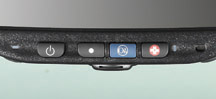
| OnStar Introduces Factory Activation |
Beginning with 2004 model vehicles, OnStar will introduce factory activation
(fig. 7). This eliminates the need for your
dealership to activate OnStar for a customer. The vehicle will leave your
inventory with the following OnStar services available: - Emergency Services - Air Bag Deployment Notification - Theft Recovery Assistance TIP: Salespeople should include a discussion of OnStar’s benefits and services in the delivery process. Service Considerations With factory activation, it is important not to exchange OnStar modules from one new vehicle to another. If new modules are swapped, OnStar will create an account with the wrong customer information. When your dealership sales department submits the customer delivery record (CDR), OnStar will create an OnStar account for the customer, and will subsequently contact the vehicle to configure the OnStar system. Once the system is configured, all OnStar services will be available, including OnStar personal calling (may not be available in some markets). In addition to the CDR data, OnStar also receives built data from the assembly plant, including specific Information from the OnStar module: - Station ID (STID) number - Electronic Serial (ESN) - Mobile Identification Number (MIN) or phone number When the vehicle leaves the assembly plant, the OnStar wake-up cycle (DRx or Discontinuous Receive) is turned on. For more information on DRx, refer to the April 2003 Techlink. With the vehicle turned off, the OnStar system will power up for one minute out of every ten minutes to allow the OnStar call center to contact the vehicle. The OnStar call center uses CDR and assembly plant information: - to identify the appropriate phone number to call - to determine the wake-up time, to know when to call the vehicle - to successfully make a data connection - to perform the configuration Dealer Theft Recovery As a result of factory activation, OnStar will be modifying the dealer theft recovery assistance process to better meet dealer needs. One result will be a rapid response to vehicle thefts from dealer inventory. More information will be communicated in the coming months. Watch GM Messenger (US only) for details on factory activation and dealer theft recovery assistance. Blue Button TIP: Any time you service an OnStar system and any OnStar module is replaced, it is necessary to press the Blue Button, speak to an OnStar advsior, and update the customer’s account. This is true even if the customer does not have nor does not intend to have an OnStar subscription. - Thanks to Dale Tripp |
|||||||||||||||||||||||||||||||||||||||||||||||||||||||
|
|
||||||||||||||||||||||||||||||||||||||||||||||||||||||||
|
|
||||||||||||||||||||||||||||||||||||||||||||||||||||||||
| Upgrading Factory Installed OnStar® Gen 2.0 Equipped Vehicles to Gen 2.6 | Note
these corrections to bulletin 01-08-46-008.
|
|||||||||||||||||||||||||||||||||||||||||||||||||||||||
| return to Table of Contents |
||||||||||||||||||||||||||||||||||||||||||||||||||||||||
|
|
||||||||||||||||||||||||||||||||||||||||||||||||||||||||
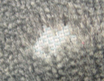
| Repairing Napped Fabric |
HSeats
on the following vehicles may be upholstered in napped fabrics, with
Dorchester on the bolster and Honeycomb on the insert. |
|||||||||||||||||||||||||||||||||||||||||||||||||||||||
 figure 9 |
||||||||||||||||||||||||||||||||||||||||||||||||||||||||
 figure 10 |
||||||||||||||||||||||||||||||||||||||||||||||||||||||||
 figure 11 |
||||||||||||||||||||||||||||||||||||||||||||||||||||||||
| return to Table of Contents | ||||||||||||||||||||||||||||||||||||||||||||||||||||||||
|
|
||||||||||||||||||||||||||||||||||||||||||||||||||||||||
| Trap Alert Sensor Service | A
small number of 2001 Chevrolet Impalas and Monte Carlos were built with
the Trap Alert system (January 2001 TechLink). GM has made the decision
to not replace the Trap Alert sensor if it fails, but to comply with anti-entrapment
regulations through other means. If repairs are necessary, contact TAC
for further assistance. - Thanks to Jerry Garfield |
|||||||||||||||||||||||||||||||||||||||||||||||||||||||
|
|
||||||||||||||||||||||||||||||||||||||||||||||||||||||||
| Active Digital Wheel Speed Sensors | Vehicle
platforms other than the Malibu will also use the Delphi 7.2 system, but
only the 2004 Malibu will incorporate a new “active” digital
signal wheel speed sensor (fig. 12 and 13). A Sensor B Connector C Drive Bearing D Non-Drive Bearing In the 2003 and earlier Malibu, the Electronic Brake Control Module (EBCM) received an analog signal from a “passive” speed sensor at each wheel. The passive wheel speed sensor creates an A/C voltage signal that varies in frequency and amplitude as the vehicle wheel speed changes. The EBCM internally converts the frequency and amplitude of the analog signal into digital information that the EBCM can use to perform ABS braking. Operation The active wheel speed sensor sends a D/C square wave signal to the EBCM instead of an A/C signal and cannot generate its own signal voltage. So, active wheel speed sensors use a separate 12V reference circuit supplied by the EBCM and chassis ground. The active wheel speed sensor harness has two wires to the EBCM, one for the signal input and one for the 12V reference. The reference voltage is supplied to an internal semiconductor in the active wheel speed sensor called a Hall Effect Sensor. The Hall Effect Sensor creates a magnetic field around the sensor. A rotating metallic toothed ring inside the wheel bearing interrupts the magnetic field as the wheel spins. When a tooth passes near the Hall Effect Sensor, the signal voltage output toggles from low to high, creating a square wave D/C output. The frequency of the D/C square wave signal output increases with wheel speed, but does not increase in amplitude. The EBCM uses the frequency to interpret wheel speed for ABS operation. The advantage of a digital active wheel speed sensor is that the signal input is much more accurate. Because of the increased signal accuracy, the ABS system can react faster to wheel slip. Also, the speed at which ABS can be activated can occur at slower vehicle speeds. Diagnostic Tips Diagnostic procedures of active wheel speed sensors are unlike that of analog passive wheel speed sensors. In the past, resistance values on analog passive wheel speed sensors could be checked to diagnose an internal open inside the sensor. On active wheel speed sensors, the normal resistance value of the sensor is in the mega-ohm range (near open). As a result, active wheel speed sensor operation must be checked dynamically. Before the sensor can be diagnosed, the 12v sensor reference circuit must be checked. Once the sensor reference voltage circuit has been verified OK, the wheel speed sensor signal circuit is diagnosed using an ammeter. With the ammeter connected in series in the signal circuit, current on the sensor signal circuit can be observed to toggle from high to low as the wheel is spun very slowly. If at any time the connection between the sensor and the sensor signal circuit is lost, the EBCM disables the sensor signal circuit for the remainder of the key cycle and a DTC is set. TIP: Be sure the digital multimeter has an intact internal ammeter fuse, to avoid DTCs during the diagnostic procedure. If a wheel speed sensor DTC is set during a functional wheel speed test, the wheel speed sensor will no longer output a signal. - Thanks to Ray Gearhart |
|||||||||||||||||||||||||||||||||||||||||||||||||||||||
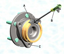 figure 12 |
||||||||||||||||||||||||||||||||||||||||||||||||||||||||
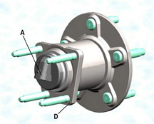 figure 13 |
||||||||||||||||||||||||||||||||||||||||||||||||||||||||
| return to Table of Contents | ||||||||||||||||||||||||||||||||||||||||||||||||||||||||
|
|
||||||||||||||||||||||||||||||||||||||||||||||||||||||||
| Lock/Unlock Verification with Remote Keyless Entry | On
Venture, Silhouette and Montana vehicles, lock/unlock verification when
using RKE is provided by MALL module 4, which is ordinarily used on vehicles
with UA6 theft deterrent. To provide horn verification on a larger number of vehicles, MALL 4 was installed on non-UA6 models beginning December 2002 and was discontinued July 2003 because of the confusion explained below. In April, circuit 301 was added between the MALL module and DRL, to provide verification with the lights as well as the horn. On vehicles with MALL 4, but not UA6, if the vehicle is locked with RKE and unlocked with the key, the alarm system goes off (even though the vehicle technically does not have theft deterrent). The unlock button on the key fob will stop the alarm. This is often diagnosed as a mis-build; it is not. If a customer raises this concern, there are several solutions: 1. Explain that if the vehicle is locked with RKE, it must unlocked with RKE. Point out that they have limited theft deterrence at no cost. The key cylinder is not tied into the alarm, nor is there a panic button on the key fob. 2. Theft deterrence may be disabled using the customization procedures in the owner's manual for MALL 4. Lock/unlock confirmation will still be available with horn and lights, but theft deterrence will be disarmed. TIP: It is not necessary to replace the MALL module. The first printing of the 2004 owners' manual incorrectly shows lock/unlock confirmation available on MALL 3. - Thanks to Tom Geist |
|||||||||||||||||||||||||||||||||||||||||||||||||||||||
| return to Table of Contents | ||||||||||||||||||||||||||||||||||||||||||||||||||||||||
|
|
||||||||||||||||||||||||||||||||||||||||||||||||||||||||
| Rear Storage Compartments | The
hinge or support link in the rear storage compartment of 2002-03 Venture,
Silhouette, and Montanta may break (fig. 14).
Bulletin 03-08-110-001 addresses this condition. The support link (also called hinge) is available as a separate replacement component. 88987165 Link (Gray) 88987166 Link (Neutral) TIP: Replace the support link, rather than the entire rear storage compartment. - Thanks to Tom Geist |
|||||||||||||||||||||||||||||||||||||||||||||||||||||||
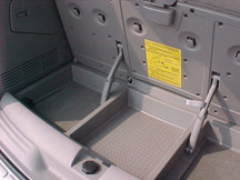 figure 14 |
||||||||||||||||||||||||||||||||||||||||||||||||||||||||
| return to Table of Contents | ||||||||||||||||||||||||||||||||||||||||||||||||||||||||
|
|
||||||||||||||||||||||||||||||||||||||||||||||||||||||||
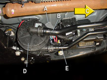
| Adjustable Pedals | Electrically
adjustable pedals are available on the 2004 Malibu (fig.
15). You can find service information in SI under Accessories/Adjustable
Pedals. The adjustable pedal system includes these major components: - Switch (operated by the driver) - Adjustable pedal module - Adjustable pedal actuator (electric motor) - Accelerator pedal bracket assembly - Brake pedal assembly - Cable - Adjustment position sensor Operating Logic The pedal system is enabled/disabled by controlling the ground side of the motor circuit. The system is enabled only when the transmission is in Park. Operating voltage is supplied through a 10-amp fuse to the driver’s switch. The BCM provides battery voltage to the pedal module to disable, and 0 volts to enable. When the system is enabled, the driver can move the pedals forward or backward using the pedal switch. The switch provides B+ and ground to the motor in whichever direction the driver chooses. The pedal actuator motor operates the accelerator pedal assembly directly, and operates the brake pedal assembly through a cable. When the motor is moving the accelerator pedal, a brake pedal position sensor monitors simultaneous movement of the brake pedal. If movement does not occur, the module disables system operation. Service Tips Whenever the cable joining the motor to the brake pedal is disconnected at either end, a new cable must be installed. Do not re-install the old one. When installing the brake pedal position sensor, be sure the sensor is correctly installed to the bracket. Then be sure the sensing arm is correctly installed. The brake pedal and accelerator pedal positions must be synchronized when components are replaced. Failure to do so will result in improper operation. Refer to Adjustable Brake Pedal Cable Replacement in SI for the synchronization procedure. You can use a No. 2 square drive tool to move the brake pedal assembly forward or backward as necessary when the cable is disconnected. - Thanks to Toby Dunmore |
|||||||||||||||||||||||||||||||||||||||||||||||||||||||
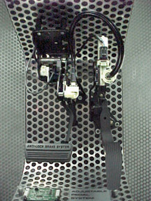 figure 15 |
||||||||||||||||||||||||||||||||||||||||||||||||||||||||
| return to Table of Contents | ||||||||||||||||||||||||||||||||||||||||||||||||||||||||
|
|
||||||||||||||||||||||||||||||||||||||||||||||||||||||||
| TAC New Product Action Centers | New
vehicle and component launches for the remainder of the 2003 calendar
year will be supported by New Product Action Centers. The primary objectives
of the New Product Action Centers are: - Identify and resolve new product concerns as quickly as possible. - Gather appropriate data and act on it to prevent recurrences of product concerns. - Respond to dealer calls utilizing maximum resources available at GM to repair customer vehicles at your dealership. The Action Center Team includes SPO Contact Centers (GM TAC, SPAC, ParTech, PQC), Brand Quality, Assembly Plants, Engineering, Regional Service Engineers, and SI Teams. Products Included in New Product Action Centers are: - Hi feature V6 - Chevrolet Malibu (includes hi value V6) - Cadillac SRX - Cadillac XLR - Chevrolet SSR - GMC XUV - GMC Canyon, Chevrolet Colorado - Aveo - GTO Dealer interface with the Action Centers will be through GM Technical Assistance, using the regular GM TAC phone number: 1.877.446.8227. Please utilize all new product service information and resources available at your dealership for these new products. If you are still unable to resolve a product concern, contact GM TAC and follow the revised prompts to access the appropriate New Product Action Center Consultant. After choosing to speak to a consultant at the Main Menu, you have 3 choices: 1. OnStar/XM Radio consultant 2. TAC consultant 3. New Product Action Center consultant After choosing 3, New Product Action Center consultant, you will be asked to choose which vehicle you are working on. After choosing the appropriate vehicle, you will be given a choice of 5 general vehicle areas vehicle manned by specially trained consultants for that specific vehicle/component. 1. Engine 2. Drive train -- includes transmissions, transfer cases and axles 3. Chassis -- includes steering, suspension and brakes 4. OnStar and XM radio 5. Body, Electrical/Accessories, or HVAC A service VME and/or GM Messenger message will announce the specific Action Center start and end dates. The prompts will be in place at GM TAC for the entire time of the New Product Action Center operation. We thank you in advance for your participation and support of the New Product Action Centers. - Thanks to GM Technical Assistance |
|||||||||||||||||||||||||||||||||||||||||||||||||||||||
| return to Table of Contents | ||||||||||||||||||||||||||||||||||||||||||||||||||||||||
|
|
||||||||||||||||||||||||||||||||||||||||||||||||||||||||
| Intermittent Dead Battery | If
the owner of a 2002-2003 Trailblazer, Envoy, or Bravada experiences an
intermittent dead battery, determine if the IGN 0 circuit is turning on
with the key removed from the ignition switch. This can be determined
by watching whether the PRNDL display and the battery light turn on when
wiggling the lock cylinder with the key removed. If the IGN 0 circuit is turning on with the key removed, replace the ignition switch. - Thanks to Dan Fuller |
|||||||||||||||||||||||||||||||||||||||||||||||||||||||
| return to Table of Contents | ||||||||||||||||||||||||||||||||||||||||||||||||||||||||
|
|
||||||||||||||||||||||||||||||||||||||||||||||||||||||||
| SRX Tire Rotation | On
the 2004 Cadillac SRX, due to dissimilar front and rear tire widths,
the tire and wheel assemblies cannot be rotated from front to back.
They may be rotated from side to side. Wheel and tires sizes are based
on the engine in the vehicle.
|
|||||||||||||||||||||||||||||||||||||||||||||||||||||||
| return to Table of Contents | ||||||||||||||||||||||||||||||||||||||||||||||||||||||||
|
|
||||||||||||||||||||||||||||||||||||||||||||||||||||||||
 Car Issues – Fix It Right The First Time
 |
||||||||||||||||||||||||||||||||||||||||||||||||||||||||
|
||||||||||||||||||||||||||||||||||||||||||||||||||||||||
| return to Table of Contents | ||||||||||||||||||||||||||||||||||||||||||||||||||||||||
|
|
||||||||||||||||||||||||||||||||||||||||||||||||||||||||
|
||||||||||||||||||||||||||||||||||||||||||||||||||||||||
|
||||||||||||||||||||||||||||||||||||||||||||||||||||||||
| return to Table of Contents | ||||||||||||||||||||||||||||||||||||||||||||||||||||||||
|
|
||||||||||||||||||||||||||||||||||||||||||||||||||||||||
| Know-How Broadcasts for November |
|
|||||||||||||||||||||||||||||||||||||||||||||||||||||||
| return to Table of Contents | ||||||||||||||||||||||||||||||||||||||||||||||||||||||||
 Truck Issues – Fix It Right The First Time