| |
| |
Note: Click a picture or illustration in the left column to view a large version in the article.
To hide the large version, simply click on it.
|
|
GM Hybrid Trucks |
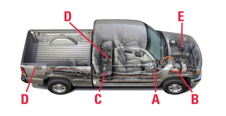
After being introduced in limited numbers in 2004, the Chevrolet Silverado and GMC Sierra Hybrid Trucks will be available nationwide in 2006 (fig. 1).
In the city driving cycle, these trucks offer a fuel economy improvement up to 10% over the conventional pickup, with little sacrifice in performance or towing capacity. They’re also available in both 2wd and 4wd.
Overview
The GM Hybrid Truck is powered by the same powerful and reliable Vortec 5300 V8 engine as the conventional gasoline truck.
A hybrid system electric starter/generator built into the transmission bellhousing replaces the conventional starter motor and conventional generator.
An underhood Starter Generator Control Module (SGCM) and 42 V energy storage module under the rear seat complete the major components of the system.
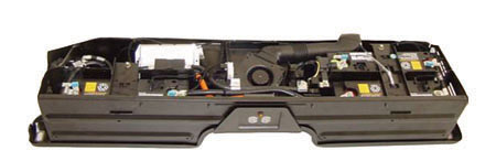
Related components include four 120 Vac ground-fault protected outlets, 42 Vdc powered electro-hydraulic steering pump, a Hybrid Control Module, and safety and control components (fig. 2).
A Electric Starter/Generator
B Starter Generator Control Module (SGCM)
C Energy Storage Module
D 120 Vac Outlets
E Electro-Hydraulic Power Assist
Operation
Significant fuel saving is realized because engine fuel is shut off during coast or deceleration, and the engine is completely stopped when the vehicle is moving at less than 10 mph (16 km/h). Additionally, braking and deceleration torque energy is recovered and stored as electrical energy in 42 Vdc batteries.
Because the engine is off during what would ordinarily be idling time, emissions are also reduced.
When the brake pedal is released, the engine restarts instantly, quietly, smoothly and automatically. The hybrid starter/generator also provides torque smoothing during downshifts and during engine on/off cycles.
TIP: The hybrid components never provide traction power.
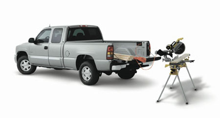
120 Vac power outlets are provided for tools and appliances (fig. 3). Two are located beneath the rear seat and two are located in the pickup box.
Because power steering and brakes may be needed when the engine is off, a 42 Vdc pump provides hydraulic assist on demand.
Starter/Generator Details
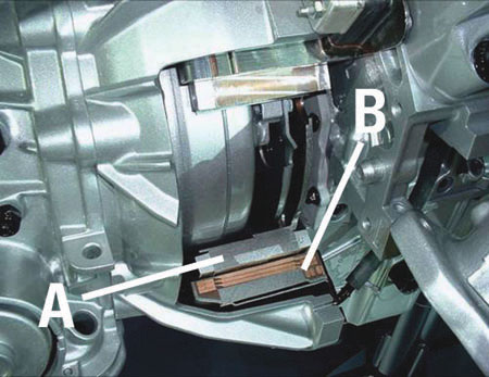
The starter/generator is located inside the standard-length transmission bellhousing (fig. 4). The stator is attached to the rear face of the engine, while the rotor surrounds the transmission torque converter and is bolted to the engine crankshaft. It turns any time the engine is running.
A Rotor
B Stator
During initial startup and restarts, the starter feature of the starter/generator converts electrical energy into torque to spin the crankshaft. Unlike conventional starter motors, this unit operates on 3 phase alternating current.
While the engine is running or the vehicle is decelerating, the generator feature of the starter/generator converts rotational torque into electrical energy, which is distributed by the SGCM, explained next.
SGCM Features
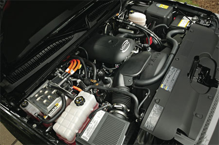
The Starter Generator Control Module (SGCM) is located under the hood (fig. 5). It acts as a traffic cop to direct and distribute electricity throughout the system as needed:
- from the generator
- to and from the 42 V batteries
- to the power steering pump
- to the 120 Vac outlets
- to the underhood 12 V battery
- to various vehicle systems
If a vehicle requires a jump start, the SGCM converts 12 V from the source vehicle to the 42 V required by the Hybrid Truck’s batteries.
All of this switching and controlling of electricity creates heat which is removed from the SCGM by a liquid cooled condenser and separate radiator.
Energy Storage Batteries
The 42 V system storage batteries consist of three sealed, valve-regulated lead acid modules, with 45 amp hour cells. The batteries provide power to operate vehicle accessories when the engine is not running, and of course provide power to start the engine on demand.
The storage batteries are located under the rear seat in an energy storage box (fig. 6). An Energy Storage Control Module monitors current, voltages and temperatures. It calculates the state of charge, and controls a cooling fan and the safety disconnect relay.
Safety devices include a 400 amp series fuse, manual disconnect switch (which “safes” the system for service), a battery cutoff switch triggered by air bag deployment, a ventilation fan, and gas vent ducting.
IMPORTANT: Battery charge must be maintained while the vehicle is in the dealership storage lot before sale.
Hybrid Control Module
The hybrid control module (HCM) near the PCM acts as a gateway between the high-speed GMLAN and Class 2 local area networks. The HCM also:
- Controls automatic engine starts and stops
- Controls the energy flowing into/out of the 14-volt and 42-volt batteries
- Enables and disables power for the auxiliary power outlets
- Enables and disables surge smoothing/active damping
- Disables 42V power distribution after airbag deployment
- Controls the auxiliary transmission pump, the power maintenance relay, and the auxiliary heater pump
- Controls starter/generator speed during transmission downshift assists
Hybrid System Service
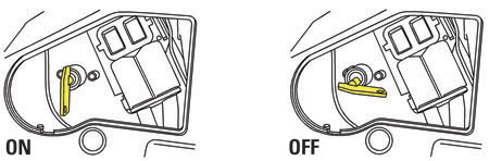
CAUTION: To reduce the risk of severe shock and burns, always disconnect the 42 V energy storage box (ESB) before doing any work to the ESB system. To disconnect the ESB, turn the engine off.
Locate the service disconnect switch on the passenger side of the ESB and turn it to OFF (switch turned on in fig. 7 and turned off in fig.8).
Battery Charge
Refer to the Service Charge Procedure in SI for details. These are some of the unique points.
- Requires use of scan tool, including CANdi module
- Service disconnect turned to ON position
- Use manual battery charger on underhood battery
- The ESCM monitors the battery pack and will stop the Service Charge Procedure when 100 percent state of charge is met.
- Can take up to 5 hours
Replacement of one or more batteries requires a unique charging procedure that must be followed for proper vehicle service. Refer to Battery Charging in SI.
- Thanks to Doug Ritter and Stephen Cichy |

figure 1 |

figure 2 |
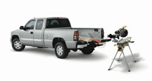
figure 3 |
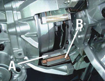
figure 4 |
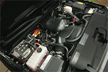
figure 5 |
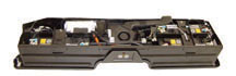
figure 6 |
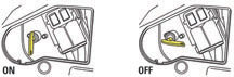
figure 7, figure 8 |
| return
to Table of Contents |
|
|
| Hybrid Truck Training and Tools |
Training
Because the hybrid systems interact with several other vehicle systems, technicians in the following categories may be involved in performing service on the hybrid trucks: engine performance, electrical system, transmission, steering, brakes and HVAC.
GM Service Technical College is offering a web-based hybrid truck training course:
Silverado - Sierra Hybrid Truck: Theory, Operation and Service (18050.01W)
If you have questions, contact the GM Training Help Desk at 888.748.2687 or in the “contact us” area at www.gmtraining.com.
IMPORTANT: Hybrid parts are on restriction and must be obtained through TAC. Authorization will not be given unless a technician has completed the training course.
Tools
The following tools are required to service the hybrid truck (available from SPX/Kent-Moore 1.800.345.2233):
J-41479-2A Seal Holder Assembly
EL-48045 EHPS Crimp Tool
EL-42000-30 Battery Terminal Adapters
J-42634 AGM Battery Charger
J-43679-A Battery Lift Hooks
J-46093 Stator Holding Tool
J-46143 Surge Tank Adapter
- Thanks to Lisa Kennedy and Kevin Larson
|
| |
| return
to Table of Contents |
|
| Tech 2 Rumors |
A TechLink article in April, 2003 addressed the issue of the Tech 2’s expected lifespan and eventual replacement. In part, it said, “The Tech 2 isn’t going to be replaced until a vehicle operating system comes along that the Tech 2 can’t be made to talk to.” Although a new vehicle operating system is now closer than it was when the earlier TechLink article was published, the wisdom stills holds true.
Even so, questions continue to be asked. Will the Tech 2 be replaced? When? What should I do about my current Tech 2? My shop needs another Tech 2, but should we get a new one now or wait for the replacement? Should we buy a CANdi module for the Tech 2?
So, it’s time to put the concerns to rest once more.
First, to get some terminology straight, the new equipment isn’t going to replace the Tech 2. It’s going to complement it. This isn’t just playing with words. When the new equipment comes out, it won’t support the older vehicles. So, the Tech 2 will still be needed to communicate with and diagnose all of the vehicles up to that point.
Second, the new equipment will be phased in, as vehicles are introduced with the new operating system. Some vehicles with today’s operating system will continue to be built, and will eventually be replaced over a span of several years. The important thing is that you won’t be asked to buy equipment before it’s absolutely needed. Right now, that looks like sometime during the 2007 calendar year, depending on which brands your dealership supports. More information will be reported when it’s available.
This means that if you need an additional or replacement Tech 2 right now, you can purchase it with confidence that it will remain useful and completely supported for many years, even well beyond the introduction of the next generation equipment.
Third, let’s not call the new equipment the “Tech 3.” It’s still early in development, and an official name hasn’t yet been selected.
So, What’s Coming?
The present thinking is that the new diagnostic system will most likely use a PC-based user interface. Initially, it will focus on reprogramming functions, with additional capabilities phased in for subsequent model years.
- Thanks to Dan Doss and Mark Stesney |
| |
| |
|
return to
Table of Contents |
|
Tech 2 Repair Service in Canada |
Canadian dealers should contact Custone for Tech 2 repairs.
The Techline Customer Support Center (TCSC) 1.800.828.6860 English or 1.800.503.3222 French offers support for first line troubleshooting. In the event the unit requires additional support; TCSC will instruct customers to send the unit to the appropriate repair center for their region.
In Canada:
Custone Electromotive, Inc.
1150 Champlain Court
Whitby, Ontario LIN 6K9, Canada
Telephone: 905.668.2664
Website: www.custone.com
E-mail: service@custone.com |
| |
| return
to Table of Contents |
|
| Tech 2 Value Kit |
GM is introducing a new Tech 2 Value Kit. Now you can purchase an additional Tech 2, and use the accessories you already have. The value kit includes only the essentials:
- Tech 2
- DLC cable
- 16-pin adapter for all NAO vehicles
- 32 mb card
Accessories and storage case are available at extra cost.
The value kit saves you more than $400. Contact SPX/Kent-Moore at 1.800.gmtools for details.
- Thanks to Mark Stesney and Sue Sulewski |
|
| return
to Table of Contents |
|
CTS Transmission Oil Cooler Line Fitting Service |
The following information applies to the 2003 through present Cadillac CTS vehicles with automatic transmissions.
IMPORTANT: Many radiators are being damaged because they are not being removed correctly.
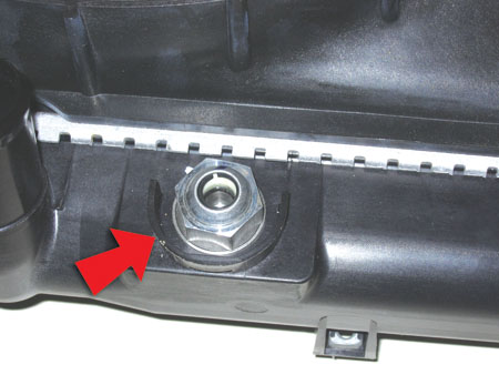
Radiators on these vehicles have two non-serviceable transmission oil cooler (TOC) fittings that mount the in-tank cooler to the plastic radiator end tank. These fittings are also non-removable. A protective wall is placed around the fitting to prevent wrench access (fig. 9).
A threadlocking compound is used to retain the fittings to the in-tank cooler. Any attempt to remove these fittings will damage the threads on the in-tank cooler and damage the seal between the in-tank cooler and the plastic radiator end tank. This can result in a coolant or transmission oil leak and possible vehicle damage.
Proper removal of the TOC line requires the use of J-44827 (fig. 10) to properly disengage the TOC line from the fitting (fig. 11). Refer to SI for the service procedure for correctly disconnecting and re-connecting the TOC lines from the fittings.
- Thanks to Bruce Ross |

figure 9 |
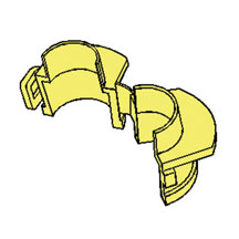
figure 10 |
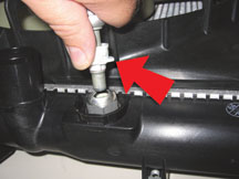
figure 11 |
|
return to Table of
Contents |
|
| Service Manual Goes Global |
As a part of GM’s continuing evolution as a global company, we have changed the Table of Contents for the service manual so that it can be used by all of GM, the world over. No longer will there be different service manual styles and layouts for the various GM regions, such as Asia-Pacific, Europe or Latin America.
When vehicles come to North America from other regions, such as the Pontiac GTO, we have to recreate the service manual content for that vehicle in our North American style of layout.
For instance, Holden provided a service manual for the GTO, but its layout was very different from what’s in SI. It had to be converted, to make it easy for you to find what you want to know.
If you multiply this by all of the vehicles GM sells here, it would be pretty confusing for you to find things if they weren’t converted.
To create a new Table of Contents, a team from all of GM’s world-wide operations worked together to develop the G-TOC – or Global Table of Contents.
GM’s North American format was used for most areas. Engine, Transmission, HVAC, Steering, Suspension, Brakes and General Information have not changed. Other areas have only minor changes. The big change is in the Body area.
How the Table of Contents is Used
When you use the electronic service manual, you select the year, make, and model, followed by the “Select a Vehicle Publication to View.” Then the “Select a Category” list appears. This first list of categories is the main Table of Contents. From here you can choose Bulletins, General Information, Brakes, Engine, Body, etc. When you click on one of these, a second “Select a Category” list appears. This is the next level of the Table of Contents. The categories you find here depend on what you selected on the first category list.
If you click on Body, you are taken one step deeper into the manual. If you then select “Interior Trim,” you find that the next screen will provide still another list of categories. In this case they are usually Specifications, Repair Instructions or Special Tools and Equipment. If you select “Repair Instructions,” you are then given a list of individual documents.
This whole process started with the first selection you made. Each choice you make from there gets you deeper and deeper into the manual until you find the exact item you are looking for.
Compared with the present North American Table of Contents, we are changing and expanding the definitions of some of those categories. The name of the individual documents will remain the same, but some will be found in different locations.
Next month, we’ll provide you with a map of where things are right now, and where they will be in the new format. If you like to use the keyword search feature, it will continue to work just as it did before. In fact, the electronic service manual will work just as it does today. Only the location of some information will be moved.
The new format will be used for all 2007 and future model year vehicles. The 2006 and prior year vehicles will continue to be just as they are today. Keeping you in touch with the changes in navigation of our information is important, so we’re doing all that we can to make this as painless as possible.
To review: the look and feel of the electronic service manual is unchanged. You access it and use it just as you do today. The Category lists will change a bit. Body will include more categories to choose from, and you will find different sub-categories behind those new choices.
Next month’s TechLink will show you how the new Table of Contents looks.
- Thanks to Bob Scherer |
| |
| return
to Table of Contents |
|
|
Connector End Views |
If you’ve done any diagnosis or repair of electrical components, you’ve been exposed to the SI wiring schematics and the accompanying connector end views.
Previous Connector End View Information
In the past, the connector end view information in SI included the connector part number and brief description. For each terminal, a table offered pin number, wire color, circuit number, and function.
While useful, this information was limited. Technnicians have requested more help in determining the proper terminal to use when making an electrical connector repair. (As explained in the September 2005 TechLink, harness repair is preferred to harness replacement in most cases.)
New Connector End View Information Phase-In Schedule
Your concerns were listened to, and a solution is in process.
A phase-in of new, enhanced connector end view information was started with the 2005 model year (see table) and will be completed in 2008.
Service Connector Part Number
and Terminal Part Information |
2005 |
Uplander, Montana, Terraza, Relay |
2006 |
H3, Lucerne, DTS, HHR, Solstice, Monte Carlo, Impala |
2007 |
All Utilities and Pickups, SKY, Acadia, Outlook, AURA |
2008 |
All remaining programs |
New Connector End View Information
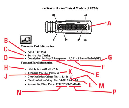
The new connector end view includes a wealth of useful information (fig. 12). As you can see in the illustration, you’ll be able to use it as “one stop shopping” for all connector and terminal information. As always, there’s a drawing of the connector end view, with each cavity identified, and a pin table as before. The features are explained below.
New Connector Body Information
A Illustration
B OEM supplier p/n
C Service p/n
D Connector description
E Number of cavities
F Each terminal type used
G Connector type
New Terminal Information
H Applicable pin numbers
J Service terminal part number
K Terminal Repair Kit tray number
L Core crimp jaw ID
M Insulation crimp jaw ID
N Terminal remover “pick” tool p/n
P Terminal test probe p/n and color
- Thanks to John Roberts
|
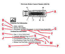
figure 12 |
| return
to Table of Contents |
|
| GM Service Communications and Fixing it Right the First Time |
To better assist GM dealers in providing customers with the best possible service experience through fixing product issues correctly the first time, we are updating our service communication strategy as it relates to product improvement information. These revisions were based on a survey of more than 500 dealership service managers and 1500 dealership technicians, and were also supported by the Fixed Operations Advisory Board. A common theme running through the survey results was to provide “one stop shopping” for all service information.
SI has been the primary source for vehicle repair and diagnostic information. Dealer technicians have been required to search for existing service information as one of the first steps in Strategy Based Diagnostics (SI Document 6856) and before calling Technical Assistance for help on a specific vehicle issue.
SI now becomes the primary source for all product improvement information. Because much of this information is updated daily, you will have access to the same information that we have, almost as fast as we have it.
This strategy also supports the 2:1 multiple PC initiative to get service information into the hands of technicians more quickly. Having the right number of PCs in the service department provides technicians with ready access to the information and puts it at their fingertips. Communications such as GM Messenger, Service VME, IDL and TechLink will be used as support tools or pointers to SI.
For your convenience, here’s a table of communications (for US dealers), the type of information carried, and the frequency of communication updates.
- Thanks to Ray Romeo
Communication |
Type of Information |
Updated |
1. SI |
Vehicle diagnostic, repair, and product improvement information. It will contain:
- PI’s: Latest Preliminary Information from the Technical Assistance Database
- Service Bulletins: Technical, Informational, and Field Product Reminders
- Campaign Bulletins |
Daily |
2. GM Messenger |
Delivers the most important product improvement information / Administrative Messages direct to the Service Managers mailbox |
Daily |
3. Service Manager Voice Mail |
Redefined to be a short summary of the latest breaking service information and in many cases will identify a PI, bulletin, or document number for ease of reference |
Immediately as needed |
4. IDL Emerging Issues Broadcast
|
Demonstrate new procedures or technology where video will enhance the understanding of the repair |
Second Thursday of each month |
5. TechLink |
Focuses on technology, training, tools, equipment, diagnostics, and service procedures. |
Monthly |
|
| |
| |
| |
| return
to Table of Contents |
|
| Oil Life System Reset Procedures -- Trucks
|
Many GM cars and trucks are equipped with an oil life system that determines when an oil change is required. After the oil has been changed, it’s necessary to reset the system.
Procedures for resetting 2001 through 2006 trucks are published here.
TIP: You can find copies of charts for earlier models on the TechLink website on the Internet. Look for the February and March 2000 issues.
The information for this article is the same as you will find in the applicable owner or service manual. To find this information in 2001-04 SI service manuals:
- Select the vehicle
- Select category General Information
- Select category Maintenance and Lubrication
- Select category Maintenance and then GM Oil Life System-Resetting.
Beginning with 2005, this information will only be found in owner manuals. To find this information in SI owner manuals:
- Select the vehicle
- Select Owner Manual
- Select Service and Appearance Care
- Select Checking Under the Hood
- Select Description and Operation
- Select Engine Oil Life System
TIP: You may be able to use the Search function, using the words Oil Life.
2006 HHR
1. Turn the ignition to RUN, with the engine off.
2. Press the information and reset buttons on the DIC at the same time to enter the personalization menu.
3. Press the information button to scroll through the available personalization menu modes until the DIC display shows OIL LIFE RESET.
4. Press and hold the reset button until the DIC shows ACKNOWLEDGED. This will tell you the system has been reset
5. Turn the key to LOCK.
6. Start the engine. If the CHANGE OIL SOON message comes back on, the engine oil life system did not reset. Repeat the procedure.
2001-05 Aztek
2002-06 Rendezvous
Without Driver Information Center (DIC)
1. With the ignition key in ON but the engine off, fully push and release the accelerator pedal slowly 3 times within 5 seconds.
2. Turn the key to OFF.
3. If the CHANGE ENGINE OIL message comes back on, the engine oil life monitor has not reset. Repeat the procedure.
With DIC
1. Turn the ignition to ON with the engine off.
2. Press the MODE button until the DIC reads OIL LIFE LEFT/HOLD SET TO RESET.
3. Press and hold the SET button until 100% is displayed. You will hear three chimes and the CHANGE ENGINE OIL message will go off.
4. If the CHANGE ENGINE OIL message comes back on, the monitor has not reset. Repeat the procedure.
2001-05 Montana
2001-04 Silhouette
2001-05 Venture
2005-06 Terazza
2005-06 Uplander
2005-06 Montana SV6
2005-06 Relay
1. With the ignition key in RUN but the engine off, repeatedly push the trip/reset button until OIL is displayed on the Driver Information Center.
2. Once OIL is displayed, push and hold the trip/reset button for five seconds. The number will disappear and be replaced by 100 (indicating 100% oil life remaining).
3. Turn the key to OFF.
4. If the change engine oil message comes back on, the engine oil life monitor has not reset. Repeat the procedure.
2002-04 Bravada
2002-06 TrailBlazer
2002-06 Envoy
2004-06 Rainier
Without DIC
1. Turn the ignition key to RUN with the engine off.
2. Fully press and release the accelerator pedal 3 times within 5 seconds.
3. If the CHANGE ENG OIL light flashes for five seconds, the system is reset. If the light does not flash, repeat the procedure.
With DIC
1. Press the fuel information button until ENGINE OIL LIFE appears in the display.
2. To reset the monitor, press and hold the select button while ENGINE OIL LIFE is displayed.
2004-06 Canyon
2004-06 Colorado
2006 H3
Reset Stem Method
1. Turn the ignition to RUN but with the engine off.
2. Press and release the reset stem in the lower center of the instrument cluster until the Oil Life message is displayed.
3. Once the alternating OIL LIFE and RESET messages appear in the display, press and hold the reset stem until several beeps sound. This confirms the oil life system has been reset
4. Turn the key to Lock. If the CHANGE/OIL message comes back on when you start the engine, the engine oil life system has not reset. Repeat the procedure.
Alternate Method
1. Turn the ignition key to RUN with the engine off.
2. Fully press and release the accelerator pedal 3 times within 5 seconds. Several beeps sound. This confirms the oil life system has been reset.
3. If the CHANGE/OIL message comes back on when you start the engine, the engine oil life system has not reset. Repeat the procedure.
2003-06 SSR
1. Press the fuel information button until ENGINE OIL LIFE appears in the display.
2. To reset the Oil Life System, press and hold the select button while ENGINE OIL LIFE is displayed.
3. If the light comes back on again when you start the engine, you will need to reset the system again.
2005-06 Equinox
2006 Torrent
2001-06 Sierra (Exc. some fleets)
2002-06 Sierra Denali
2001-06 Silverado (Exc. some fleets)
2001-06 Yukon and Yukon XL
2001-06 Tahoe and Suburban
2001-06 Escalade
2002-06 Escalade EXT
2002-06 Avalanche
2001-06 Yukon Denali
2003-06 Hummer H2
2003-06 Express (Exc. some fleets)
2003-06 Savana (Exc. some fleets)
1. Turn the ignition to RUN but with the engine off.
2. Fully push and release the accelerator pedal slowly 3 times within 5 seconds.
3. If the Change Oil Soon light flashes, the system is resetting.
4. Turn the key to Lock.
5. Start the engine.
6. If the Change Oil Soon light comes back on, the system has not reset. Repeat the procedure.
2002- 06 Saturn Vue
1. Turn the ignition to RUN but with the engine off.
2. Fully push and release the accelerator pedal 3 times within 5 seconds.
3. If the Change Oil Soon light flashes, the system is resetting. The light will flash for up to 30 seconds or until the ignition is turned to OFF.
4. Turn the key to OFF.
5. Start the vehicle.
6. The oil life will change to 100%.
7. If the Change Oil Soon light comes back on or stays on for 30 seconds at the next ignition cycle, the system has not reset. Repeat the procedure.
2001-06 B7 Chassis Medium Duty
1. Turn the ignition to START but with the engine off.
2. Fully press and release the accelerator pedal slowly 3 times within 10 seconds.
3. If the CHANGE OIL light flashes for five seconds, the system is reset.
4. If the light does not display for five seconds, you will need to reset the system again.
2003-06 MD 560 C-Series
All except with Caterpillar diesel:
1. Turn the ignition to RUN but with the engine off.
2. Fully press and release the accelerator pedal slowly 3 times within 10 seconds.
3. If the CHANGE OIL light flashes for five seconds, the system is reset.
4. Turn the key to OFF.
5. If the light comes back on again when you start the engine, you will need to reset the system again.
All with Caterpillar diesel:
1. Turn the ignition to RUN but with the engine off.
2. Fully apply and hold the brake pedal while you fully press and release the accelerator pedal 3 times within 5 seconds.
3. Turn the key to OFF.
4. If the light comes back on again when you start the engine, you will need to reset the system again.
- Thanks to Jerry Garfield |
| |
|
return to Table of
Contents |
|
|
Glass Cleaning Process |
Owners of some new vehicles may comment about a film or haze on inside window surfaces when the vehicle is delivered. This film results from a manufacturing process, and is most visible when headlights or sunlight shine directly through the glass. Because the film attracts moisture from the air, it can contribute to reduced visibility under humid conditions.
To ensure high customer satisfaction with the new vehicle, the windows should be properly cleaned during the final Pre-Delivery Inspection, just before customer delivery.
TIP: The following procedure should be used on all cars and trucks.
Step 1. Spray the entire inside glass surface of one window with water. Because the oily film is water-soluble, it should be removed when the glass is thoroughly wet. For this reason, do only one window at a time. You don’t want the glass to dry until you wipe it.
TIP: Use regular water only. Avoid any type of chemical cleaner. Use a clean, empty spray bottle, which can be purchased at home supply stores.
Step 2. Use dry paper towels to wipe the window. To do this, fold a sheet of paper towel in half, and wrap it around a dry sponge.
TIP: Use a paper towel only. Avoid any type of cloth.
TIP: Use a sponge about 3 x 5 inches (76 x 125 mm). It should be about the size of your hand. If it’s too large, the edges of the towel won’t wipe well. If it’s too small, your fingers may touch the glass.
The sponge will apply uniform pressure on the glass and by following its curvature will reduce finger-created streaking.
Step 3. Wipe/dry the glass surface in a uniform, linear, length-wise fashion, one swipe at a time. Avoid circular swipes. The idea is to lift the oily film into the paper towel without spreading it around by multiple swipes.
IMPORTANT: Discard each sheet of paper towel after one swipe.
- Thanks to Car and Truck Brand Quality
|
| |
|
return to Table of
Contents |
|
| A/C Vapor or Mist |
Some 2005 Chevrolet Equinox and 2005-06 Saturn VUE models may have intermittent poor A/C performance and/or a vapor/mist coming out of vents when the A/C is on.
The evaporator core may be freezing. The temperature sensor in the thermal expansion valve (TXV) controls cycling of the compressor clutch to prevent freezing of the evaporator core. There is a cavity on the TXV that the temperature sensor sits in when bolted on. The cavity must be filled with thermal grease to get an accurate temperature reading. If the cavity does not have enough thermal grease, the temperature reading will not be accurate and the compressor will not cycle off to prevent freezing of the evaporator core.
To resolve this concern, fill the temperature sensor cavity on the TXV with thermal grease p/n 22668050. Use the instruction in SI for the Air Conditioning (A/C) Refrigerant Low Temperature Sensor Replacement. This document has the removal and installation procedures for the temperature sensor.
- Thanks to Ron Erman |
| |
|
return to Table of
Contents |
|
| Rear Control Arm Noise |
Owners of some 2005-06 Chevrolet Cobalts (Pontiac Pursuit in Canada) may comment on a squawk/squeak noise that occurs when hitting bumps, or when going up/down driveways at slow speeds.
TIP:: It may be easy to blame the rear axle assembly, as the noise will sound the loudest at this point (using Chassis Ears).
Replace the lower rear control arm bushing. This bushing is in a steel retainer, about the size of a hockey puck.
TIP: Special tool J 44570A is required.
- Thanks to John Mason |
| |
| return
to Table of Contents |
|
 Car Issues
— Fix It Right the First Time (new issues in bold) Car Issues
— Fix It Right the First Time (new issues in bold) |
Model Year(s) |
Vehicle Line(s) / Condition |
Do This |
Don’t Do This |
Reference Information/Bulletin |
2005 |
Grand Prix, LaCrosse/Allure – Front Brake Moan and/or Groan Noise During Brake Apply |
Confirm that noise is coming from front brakes – then replace front brake pads. |
Don’t resurface front rotors. |
05-05-23-006 |
2004-2005 |
Grand Prix LaCrosse, Allure – Blower Motor Inoperative or Intermittent, Blower Speed May Drop or Blower Continues to Run After Key Off |
Install 330 MFD capacitor between LPM circuit and ground. |
Don’t replace LPM, blower motor or HVAC control head. |
05-01-39-001A |
2002-2005 |
Buick LeSabre – Front Door Window Binds/Inoperative/Moves Slowly |
Adjust glass. |
Don’t replace window regulator. |
05-08-64-011 |
2002-2007 |
Cavalier, Sunfire, Grand Am, Classic – Vehicle Hesitates, No Start, Lack of Power, Low Fuel Pressure |
Replace fuel pump strainer. |
Don’t replace fuel pump module. |
05-06-04-026A |
2001-2003 |
Aztek, Rendezvous – Window Regulators Separate from Window Motors |
Use window regulator clips and procedure outlined in bulletin instead of replacing complete window regulator assemblies. |
Don’t replace window regulator assemblies that are serviceable and only have broken clips. |
03-08-64-015 |
1999-2004 |
All Cars and Trucks – Brake Warranty, Service and Procedures |
Issue One: Refinish brake rotor.
Issue Two: Measure for LRO. |
Issue One: Don’t replace brake rotors.
Issue Two: Don’t measure for LRO. |
00-05-22-002D |
2002-2005 |
Cars and Trucks – Multiple Driveability Symptoms/Clogged Fuel Injectors |
Clean fuel injectors as described in bulletin. |
Don’t replace fuel injectors. |
03-06-04-030A |
|
| return
to Table of Contents |
|
|
 Truck Issues — Fix It Right the
First Time (new issues in bold)
Truck Issues — Fix It Right the
First Time (new issues in bold)
|
Model Year(s) |
Vehicle Line(s) / Condition |
Do This |
Don’t Do This |
Reference Information/Bulletin |
2004 |
Full Size Pickups and Utilities, H2 – Passenger Door Module and RKE Inoperative |
Re-flash passenger door module. |
Don’t replace passenger door module. |
04-08-52-005 |
2001-2005 |
Full Size Pickups and Utilites – Cranks But No Start, Stall, Inaccurate/Incorrect Fuel Gauge Reading, No Fuel, Vehicle is Out of Fuel and Fuel Gauge Reads Above Empty |
Replace fuel sensor. |
Don’t replace fuel sender module. |
04-08-49-018E |
2002 |
Midsize Utilities – HVAC Mode Door Actuator Replacement |
Use essential tool to replace mode actuator valve. |
Don’t use any other essential tool. |
05-01-38-001A |
2005 |
HUMMER H2 SUT/SUV – Momentary Loss of HVAC Blower Motor Operation While Adjusting Power Seats |
Install 330 mf 50V capacitor. |
Don’t replace the HVAC control head, blower motor or seat switches. |
05-01-39-004 |
2001-2005 |
Chevrolet/GMC 36 Series Cab/Chassis – DTC P1172 or P2636, Fuel Gauge Reads Empty, SES Light On |
Modify fuel tank balance line. |
Don’t replace fuel tank unit, the PCM or fuel transfer pump. |
05-06-04-008 |
2004-2005 |
Midsize and Fullsize Pickups and Utilities – CD Issues |
Load new software calibration. |
Don’t exchange or replace the radio. |
04-08-44-020A |
2002-2005 |
Tahoe, Suburban, All Yukons, All Escalades, Avalanche, H2 – Exhaust Pop/Ping Noise |
Replace heat shield. |
Don’t replace exhaust system. |
03-06-05-008B |
2004-2005 |
All Cars and Trucks – State-of-Charge Upon Delivery of New Vehicle |
Check battery state-of-charge per PDI procedure using
J-42000 or J-42000-EU. |
Don’t remove and replace battery. |
02-06-03-009A |
2002-2004 |
Silverado, Suburban, Tahoe, Sierra, Yukon/XL, Escalade EXT – Rough Idle, Misfire, MIL DTC P0300 |
Measure intake manifold for warpage across two runner ports only. Replace upper manifold gasket with teal-green gasket. |
Don’t measure intake manifold for warpage across all four intake runner ports. Don’t replace upper intake manifold gasket with orange gaskets. |
05-06-04-029 |
2001-2003 |
Fullsize Pickups – Injector Replacement for High Flow Rates |
Use Corporate Bulletin Number 04-06-04-007A for injectors with high fuel return rates. Use Special Policy 04039 for all 01-02 vehicles. |
Don’t replace 8 injectors for any complaint other than high fuel return rates. All other injector failures are fix as failed. |
Special Policy 04039 |
|
| return
to Table of Contents |
|
|
|
Know-How Broadcasts for
NOVEMBER |
| |
 |
| Know-How
Broadcasts for NOVEMBER |
|
10290.11D Emerging Issues |
November 3, 2005
9:30 AM and 12:30 PM Eastern Time
|
|
New
Model Features |
For Web NMF courses, log on to the GM Training Website (www.gmtraining.com). Select Service Know-How from the menu, then choose New Model Features for a selection of courses. |
| -
Thanks to Tracy Rozman |
|
|
return
to Table of Contents |
|