| |
|
Note:
Clicking on any picture or illustration will open a larger version
of that art.
|
BREAKING
NEWS
|
2004
Cadillac CTS models with the 3.5L V6 engine (RPO LY7) require use
of the CANdi module when using the Tech 2. Refer to the March 2003
TechLink for installation and functionality testing. The CANdi module
can remain in place for all 2004 Cadillacs. http://service.gm.com |
| return
to Table of Contents |
|
|
|
Electric
Power Steering (EPS) |
For several years,
GM vehicles have offered steering systems involving electronics.
The Magnasteer system (TechLink Dec. 2000) uses an electronically
controlled magnetic unit to vary the amount of effort needed to steer
the vehicle. Quadrasteer (TechLink, Dec 2001) uses an electronically
controlled electric motor to provide steering for the rear wheels.
Now, the 2004 Chevrolet Malibu is offering an Electric Power Steering
(EPS) system (fig. 1), which uses an electric motor to provide steering
assist to the front wheels. This eliminates the power steering pump,
hoses, control valve and piston/cylinder assembly.
The EPS motor provides a variable amount of assist directly to the
steering shaft, based on vehicle speed and input torque. The motor
and the Power Steering Control Module (PSCM) are mounted as an assembly
directly to the steering column.
TIP: Unlike Magnasteer, which is controlled by the Electronic Brake
Control Module, the EPS has its own control module.
The EPS motor is a 65 amp, brushless, 12-volt reversible unit. It drives
the steering shaft through a worm shaft and 22:1 reduction gear.
This method of providing boost is considerably different from a hydraulic
assist. In the hydraulic system, pressure is applied directly to the
steering rack to help move it side to side. On the EPS system, boost
is applied to the steering shaft, which helps the driver turn the steering
pinion.
Because the electric motor draws a large amount of current when it
is running, the system has built-in overload protection. Heat build-up
may be a factor at high ambient temperatures, when a large amount of
steering wheel movements occur in a short period of time (such as repeatedly
performing lock-to-lock turns, while standing still). It’s unlikely
that a customer will experience this.
The software in the controller keeps track of current usage and compares
that with the known heat buildup of various components. If a heat threshold
is reached, the controller uses pulse width modulation (PWM) to temporarily
limit current to the motor. This is called de-rating. In this rare
instance, the driver would notice a temporary reduction in boost.
The EPS control module depends on various inputs:
- Vehicle speed
- Steering shaft torque sensor
- Steering wheel position sensor
In a hydraulic power steering system, the input and output steering
shafts are joined by a small torsion bar. Two halves of a hydraulic
flow valve are attached, one to each shaft. When torque is applied,
the torsion bar twists, the valve halves move relative to each other,
and fluid is allowed to flow. In the electric power steering system,
the upper and lower torque sensor rotors, which use resistive elements,
are mounted to the input and output shafts. When torque is applied,
the torsion bar twists, the rotors move relative to each other, and
the movement affects the difference in resistance between the two rotors.
This electrical information is used by the PSCM as the torque input.
Boost is provided, proportional to torque. The combined torque/hand
wheel position sensor assembly is contained within the steering column.
Each EPS unit is calibrated for the vehicle in which it is installed,
which ensures the proper amount of assist and road feel. The calibration
is called the Steering Tuning Selection and is specific to the vehicle’s
VIN. It can be read from the module, using the Tech 2.
Service
The EPS motor and control unit are replaceable as an assembly. The
torque sensor and steering wheel position sensor are serviced by replacing
the steering column assembly.
If components are replaced in the EPS system, it is necessary to perform
a hand wheel position sensor calibration so the system knows where
the center position is for the steering wheel.
There’s a torque sensor zero calibration, which affects on-center
effort bias.
And, the correct Steering Tuning Selection will also have to be made
so the system knows which boost curve to use for that particular vehicle.
Diagnosis
Diagnosis of the EPS system is aided by the following data readouts
using the Tech 2 scan tool:
- Battery Voltage
- Calculated System Temperature
- Engine Speed
- Motor Command
- Motor Feedback
- Steering Shaft Torque
- Steering Position Sensor
- Steering Tuning Selection
- Steering Wheel Position
- Torque Sensor Signal
- Vehicle Speed
The PSCM module communicates using the GMLAN network.
-
Thanks to David Juarez |

figure
1 |
|
|
|
|
|
|
| DTC
Symptoms |
Background
As the complexity of GM vehicles has increased, so has the need
for additional DTC (Diagnostic Trouble Code) numbers.
For a given circuit or circuit type, 5 consecutive DTC numbers were
usually assigned in the following format:
B2700 Ignition Shift Interlock Circuit (base number)
B2701 Ignition Shift Interlock Circuit Range/Performance
B2702 Ignition Shift Interlock Circuit Low
B2703 Ignition Shift Interlock Circuit High
B2704 Ignition Shift Interlock Circuit Open
For some circuits, not all 5 of the assigned DTCs were actually needed.
But because assignments were made according to the formatting plan,
many new types of circuits consumed 5 numbers.
The list of numbers available for DTCs used on GM vehicles worldwide
was being rapidly depleted.
When the message structure of the GMLAN Serial Data Network was being
developed (see March 2003 TechLink), an additional byte of data was
included in each DTC Message. So, additional information could be displayed
on the scan tool for a circuit failure without assigning more than
one DTC number to a given circuit. This extra data is being called
the DTC Symptom.
This byte of data can be indicated with two alphanumeric characters.
The first character following the DTC indicates the DTC Symptom category
and the second character indicates the subtype of the DTC Symptom.
There’s a complete list of categories and subtypes in SI under
the 2004 XLR or the 2004 Malibu. Follow this path:
- “Build” the vehicle
- Vehicle Control Systems
- Vehicle DTC Information
- Description and Operation
- DTC Symptom Description
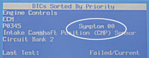
Display of DTC Symptoms
When DTC Symptoms are available on the scan tool, they will be displayed
separately from the DTC number (fig 2).
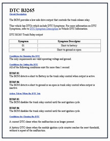
Service Information will also deal specifically with DTC Symptoms.
Information about the DTC Symptom(s) will be provided in the facing
page information for a DTC. See the accompanying sample from a facing
page (fig. 3).
In many cases, the diagnostic procedure in Service Information is the
same for a given DTC regardless of DTC Symptom. In some cases, different
diagnostic procedures will be used for different DTC Symptoms with
the same base DTC number. In either case, use the Search function in
ESI to find DTCs by base DTC number only, and if necessary, select
the appropriate procedure for the DTC Symptom after the search.
A special case of the DTC Symptom is when the base DTC is the only
malfunction identified. Additional information that a DTC symptom would
provide is not needed or recorded by the module. The base DTC number
and descriptor provide all the information that is available. In that
case, the DTC Symptom displayed is 00 (No Additional Information).
If 00 is displayed as a DTC Symptom, there is not a fault with DTC
display on the scan tool; it is just indicating that no additional
information is available..
-
Thanks to Gary Clark
|
figure
2
|
figure
3 |
| |
| |
|
|
Programmable
Radios |
At
present, radios are programmable on the following vehicles:
2003 C/K vehicles
2003 G/H vans
2003-04 Hummer H2
2004 all light and medium duty trucks
These radios must be programmed when a new unit is installed or radios
are swapped. In the past, it was necessary to call the Techline Customer
Support Center for a VCI number to complete the event. The new process
makes this phone call unnecessary.
Requirements
To use this procedure, you must be using TIS satellite version 9.0 and
Tech 2 software version 23.005 (or newer). This coverage was released
in late August.
Procedure
You will need the following information before you begin:
- RPO code of the radio you’re going to program
- RPO code of speakers
- On C/K trucks, observe if there’s a Y91 amplifier package
- On Hummer H2, observe if there’s a Y91, Y92, or no amp package
- Be aware that RPO UC6 is a six-disc in-dash CD changer.
TIP: On vehicles with RPO U42 DVD player, you must pull the DVD fuse
before programming the radio.
TIP: You must install the radio to be programmed in the vehicle before
beginning the request process.
Begin by requesting information from the vehicle. The Tech 2 will gather:
- Calibration numbers
- VIN
- Radio’s 8-digit GM part number
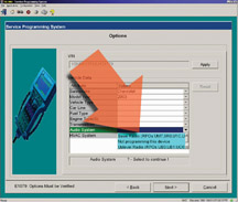
Connect the Tech 2 to a PC with the TIS application. The next part of
the process is automated and transparent. TIS will obtain the VIN and
radio 8-digit part number from your Tech 2, and will then locate and
display the appropriate Option Screen. In the turquoise area of the display
(fig. 4), make the necessary selection, based on the known radio RPO.
Fill in other option selections as required; i.e., HVAC.
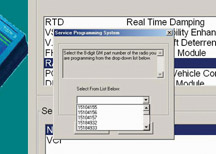
TIP: Ordinarily, the Radio Part Number Select popup will not appear,
because TIS will obtain the number from the Tech 2. But if the popup
does appear (fig. 5), it may be because
- The Tech 2 does not contain software version 23.005 or newer. In
this case, you must manually select the correct radio part number from
the
list provided. You can obtain the number from the tag on the radio,
or by using the Tech 2 Diagnostic Functions to read the number from
the
radio.
- Something is wrong with the radio.
On the Supported Controller screen, select Radio and select Normal.
Then when the Calibration screen appears, deal with each available
tab, one
at a time (fig. 6).
Under the Tuner tab, specify the country in which the radio will be
operated. This affects the range of frequencies displayed.
Under the Audio tab, you will need to make a selection based on the
radio’s
RPO code.
Under the Equalizer tab, you need to know and specify the vehicle’s
cabin and speaker configuration. This affects how the radio sounds
in its surroundings.
Return to the vehicle and download the programming data to the radio.
TIP: If you make any errors during the selection process, improper
calibrations could result in no audio and/or no chime functions. (The
radio will light
up but has no volume.) If this occurs, DO NOT replace the radio. Start
the selection and calibration process again.
Finally, as with any programming event, check for codes.
- Thanks to Chris Jenkins, Craig Jones and
Mark Stesney |
| |
 figure
4
figure
4 |
figure
5 |
figure
6 |
| return
to Table of Contents |
| |
| Accessing
GM Common Training Website (USA only) |
The
July issue of TechLink mentioned the Terminal and Connector Reference
Guide and gave the wrong instructions on how to obtain a copy.
We suggest following this path to obtain this information from the GM
Common Training website:
- https://www.gmcommontraining.com
- Use your ID and password
- Select Resources
- Select Training Materials
- Select 18043.05B - GM Terminals and Connectors Reference Guide
-
Thanks to Chris Wallace |
| |
| return
to Table of Contents |
|
| Corrections |
An
article in the July 2003 issue of TechLink involving Switch Plate
Bezel Removal contains an error in the applicable model years. It
applies to 2003 - 04.
An article in the August 2003 issue involving Front Stabilizer Shaft
Installation refers to 2003 vehicles. It should have said 2004.
|
| return
to Table of Contents |
|
| XM
Satellite Radio News |
There’s
a lot of news about XM™ Satellite Radio for the 2004 model
year.
New Models Added
First, a number of additional vehicles will be offering XM radio in 2004:
Canyon, Colorado, Envoy, Envoy XL, Envoy XUV, Grand Prix, Ion, Malibu,
Malibu Maxx, Montana, Rainier, SRX, Trail Blazer, Trail Blazer EXT, Venture,
Vibe, Vue, and XLR.
All vehicles that offered XM radio in the past will continue for 2004.
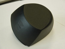
New Antenna Technology
Beginning with the 2004 model year, a new XM antenna is being installed
on some vehicles (fig. 7). The list includes Avalanche, Denali, Denali
XL, Escalade, Escalade ESV, Escalade EXT, Sierra, Silverado, Suburban,
Tahoe, Yukon, and Yukon XL. The DeVille, Seville, Bonneville, and LeSabre
will switch to this new antenna mid-year. And also mid-year, the 2004
Envoy, Envoy XL, Envoy XUV, Rainier, TrailBlazer, and TrailBlazer EXT
will switch to a different new antenna (fig. 8).
The XM antenna used in the 2002-03 model years included two different
elements, one to receive signals from the satellites, and a second one
to receive signals from the ground repeaters. Two coax cables were required.
The new antennas use one element to receive both sets of signals, and
only one coax cable is required.
TIP: The two types of antenna cannot be interchanged in service.
XM Radio Activation
At present, all vehicles with XM radio arrive at the dealership with
ten rotating free-to-air channels. It’s necessary to phone XM radio
at 800.556.3600 to activate the service. Beginning in October, the ten
free-to-air channels will be phased out. Dealers will be able to activate
all of the vehicles on their lot through a process called Rapid Activation,
turning all of their vehicles into XM demonstrators. The only information
needed to Rapid-Activate a vehicle is the 8-digit XM radio ID, obtained
by tuning to XM channel 0.
TIP: When a customer buys an XM-equipped vehicle that has been Rapid
Activated, an account is automatically set up at XM, when the Customer
Delivery Record is received.
Beginning early in calendar year 2004, all vehicles will arrive pre-activated
from the factory. Each customer will have several choices:
1. Accept the vehicle with the radio activated and enjoy 3 months of
free service before deciding to continue. XM will send information to
the customer about extending their subscription.
2. Sign up for a multi-year subscription.
3. Tell the dealer that they are not interested in 3 months of free service.
Theftlock
To deter theft, all XM receivers are programmed to learn the VIN of the
vehicle in which they are installed, using the Class 2 data line. As
soon as the VIN is learned, the unit becomes “locked.” That
is, it cannot be moved to a vehicle with a different VIN -- it will not
work. Once locked, the receiver can be installed only in the original
vehicle.
Cadillac XLR Antenna
On the XLR, the XM radio antenna must be installed during new vehicle
preparation, if the customer desires XM service. This is explained on
an instruction sheet accompanying the vehicle. It is also highlighted
in an accompanying article.
TIP: All XLR service stock antennas are unpainted, and must be painted
before installation.
Other
XM radio receivers are still on a parts restriction. After diagnosis,
call GM TAC at 877.446.8227. (The prompt for XM radio is combined with
the OnStar prompt.) After verifying your diagnosis, the TAC consultant
will order a replacement. Use the supplied pre-paid return label to return
the original receiver to avoid a non-return core charge.
Soon, you will be able to use the Tech 2 to read the serial number from
the XM radio receiver. TechLink will publish the necessary path when
it becomes available.
The XM antenna is molded of black plastic. Do not attempt to apply paint
or clearcoat; doing so can reduce system performance. This does not apply
to the Cadillac XLR antenna.
The factory location for each antenna was optimized for performance by
GM engineering. Do not attempt to relocate the antenna, as this can cause
degraded performance.
And finally, the antenna needs to be attached to a solid surface. Do
not install cloth or vinyl roof covers on XM-equipped vehicles. This
may cause degraded performance and could also lead to water leaks.
-
Thanks to Doug McKibbon
|
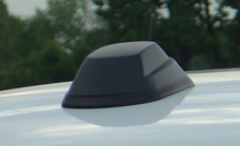
figure 7
|
figure
8 |
| |
| return
to Table of Contents |
|
| Console
Latch Lubricant |
Owners of some 1999-2003 Chevrolet and GMC fullsize pickups and utilities
with a center console may comment that the lid is hard to open or
close. According to bulletin 02-08-49-007, this may be caused by
insufficient lubrication on the latch.
TIP: Do not replace parts in an attempt to repair this condition.
TIP: If the lid will not open, depress the center console latch handle
button and give the top of the center console lid a sharp rap with your
hand.
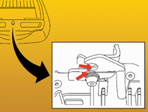
Apply a small amount of GM Dri Slide® Lubricant 1052948 (992926 in
Canada) to the center console latch, through the opening in the latch
trim plate (fig. 9). Operate the latch while spraying to work the lubricant
into the mechanism.
Open and close the console lid several times to verify the proper operation
of the latch.
- Thanks to Jerry Garfield |
figure
9 |
|
return
to Table of Contents |
|
| XM
Antenna Installation on XLR |
When
a 2004 Cadillac XLR is ordered with the optional XM radio, the antenna
is shipped loose. It must be installed before delivery of the vehicle
(at customer request). A detailed instruction sheet is supplied with
the antenna kit. Here are some highlights.
TIP: Install protective coverings over the rear compartment and adjacent
panels. The folding top must be in the lowered position and the compartment
lid open.
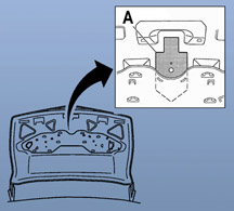
On all XLR models, an AM/FM antenna ground plate is attached to the underside
of the rear compartment lid. A supplemental ground plate/template is
supplied with the XM antenna. It must be positioned and installed before
the XM antenna is installed (fig. 10).
A Template
TIP: For the first several months of production, it will be necessary
to temporarily remove the large ground plate from the underside of the
rear compartment lid. In later production, it will be reshaped and can
be left in place. The instruction sheet provided with the antenna kit
will reflect the appropriate steps.
The XM antenna ground plate/template aligns to a recessed feature in
the rear compartment lid. It serves as a template to mark the locations
for two pilot holes on the underside of the rear compartment lid.
A strip of masking tape is used to protect the exterior surface of the
compartment lid while the pilot holes are enlarged as instructed.
TIP: After the pilot holes are drilled and enlarged, remove masking tape
and drilling remnants and use GM RTV silicone rubber sealant (12345739)
to seal the raw edges of the holes.
The XM antenna ground plate/template is equipped with an adhesive material.
Peel the backing and install the plate to the underside of the compartment
lid.
TIP: When the backing is removed, be sure the diecut discs are also removed
from the mounting holes.
Then follow the instructions to install the XM antenna, fasteners, and
wiring.
On early models, follow SI procedures to reinstall the large ground plate
to the rear compartment lid. On later models, this step will not be necessary.
Then use your Tech 2 to verify that the proper parameters are displayed,
and clear DTCs, following the instruction sheet.
The vehicle is now ready for the XM radio receiver to be activated.
- Thanks to Jason Macco |
| 
figure
10
|
| return
to Table of Contents |
|
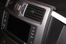
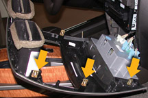
| Cadillac
XLR Trim Removal |
Here
are some tips to help avoid damage when removing the console trim
pieces on the new Cadillac XLR.
The two trim pieces are the console trim plate (which surrounds the shifter
and cupholder) and the instrument panel trim plate (which surrounds the
radio and HVAC controls).
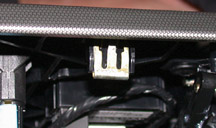
Both of these trim pieces are retained by metal clips (fig.
11), which
must be loosened by prying.
TIP: Use a plastic trim removal stick, to avoid damage to the trim or
surrounding areas.
TIP: Be sure all clips are loosened before pulling on the trim plates,
to avoid deforming the metal covering.
Refer to SI for the complete procedure. The information here is additional
tips.
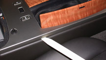
The console trim plate comes out first. Use a T-15 Torx bit to remove
the shifter handle. Then insert the trim removal stick under the edge
of the trim plate in the area of the rear clip and loosen the clip (fig.
12). Repeat this for each clip, then lift the trim plate off the console.
Refer to the photo for the clip locations (fig.
13).
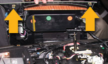
With the console trim removed, you can remove the IP trim plate. Insert
the trim stick at the upper corner and loosen the top clips (fig.
14).
Work down the sides and loosen the center and bottom clips. Then remove
the trim plate. Refer to the photo for clip locations (fig.
15).
- Thanks to Brad Thacher
|
|
figure
11 |
figure
12 |
figure
13 |
figure
14 |
figure
15 |
| return
to Table of Contents |
|
| Quality
Pre-Delivery Inspection |
Most
customers consider the condition of their new vehicle during delivery
as a direct reflection on your dealership, and on your service department.
A quality pre-delivery inspection (PDI) is critical to customer satisfaction
with their new vehicle, which is reflected in CSI and various automotive
surveys.
Bulletin 03-00-89-006 addresses the PDI process. We’re including
some critical highlights here.
Steering Wheel, Seats, and Interior Door Panels
Interior components are frequently covered in protective plastic.
TIP: Do not use any sharp object or cutting utensil to remove any plastic
coverings.
Leather Steering Wheels -- With your hands at 11 o’clock and 2
o’clock positions, pull the plastic from behind the wheel toward
you and then downward. Do not allow it to twist or bunch up. If there’s
a second layer of thin plastic wound around the wheel, unwind it. Do
not twist it into a wire-like bunch. It could damage the leather.
Seats and Panels -- Plastic wrap caught behind moldings or bezels may
require removal of these trim pieces to remove the plastic. Do not remove
residual adhesive with a razor blade. Do not expose the surfaces to harsh
chemicals.
TIP: The bulletin lists adhesive removers and cleaners that can be safely
used on various interior surfaces. These products must be used with care.
Space does not permit repeating the instructions here. Follow the instructions
on the labels.
Tire Pressure
Tires are inflated at the factory to 35-41 psi (241-283 kPa) to assure
proper tire bead seating.
Tires must be inflated to the recommended pressure before delivery, including
the spare tire. Improper tire pressure may result in ride, handling and/or
noise concerns.
Verify and adjust the tire pressures to the PSI found on the tire placard.
The placard may be located on the front or rear door jamb, inner trunk
lid, or IP compartment lid, depending on model.
TIP: Do not set to the pressure indicated on the tire sidewall.
Exterior Protection
The following list, although not exhaustive, includes some ways you can
minimize damage to vehicles at your dealership.
- Leave exterior protection devices such as plastic sheeting and foam
block door protectors in place up to the time of delivery. (This does
not apply to display vehicles.)
- In northern areas, be careful with ice scrapers and snow shovels. Consider
using plastic implements in storage lots.
- Keep bushes and shrubs trimmed around vehicle storage lots.
- Maintain your dealership car wash equipment. Be sure personnel who
prep new vehicles avoid belt buckles, metal snaps, etc. on their uniforms.
Perceived Fuel Economy
In addition to the information in the bulletin above, there’s also
the matter of perceived fuel economy, particularly on vehicles with a
Driver Information Center (DIC). This is covered in Informational Bulletin
03-00-89-021.
To ensure that the fuel economy displayed is a reflection of the owner’s
driving habits and vehicle usage, it’s necessary to reset the fuel
economy readout just before delivery.
TIP: The way the vehicle is handled during manufacture and shipping may
leave inaccurate values in the DIC.
Refer to the appropriate Owner’s Manual for the reset procedure.
You will find all 2004 Owner’s Manuals on SI.
-
Thanks to Diana Sancya |
return
to Table of Contents
|
|
| Follow
the Links to Complete Diagnosis and Repair |
Following
a repair procedure or diagnostic chart in SI is much like following
written directions when you’re driving to an unfamiliar place.
That is, you must follow every step, in order, without skipping any.
Otherwise, you probably won’t end up where you’re supposed
to go.
In SI, many instructions contain links (underlined and displayed
in blue) that take you to additional, related instructions. It may be tempting
to ignore these links, but you must click each link and perform the instructions
they lead to. Doing otherwise could cause you to overlook or completely
miss important steps.
How SI is Organized
To understand this fully, it helps to know a little bit about how SI
is organized and developed.
Many service or diagnostic procedures are broken down into numerous subroutines,
which can be assembled by the SI developer as needed to complete an overall
procedure. Put another way, an overall procedure may consist of a string
of related subroutines. In many cases, a certain subroutine is used in
more than one procedure. To conserve space, the SI developer places a
link in the procedure to take you to the necessary subroutine, instead
of reproducing it each time it’s used.
(Your own toolbox works like this. You have only one 1/2-inch ratchet
wrench, but you assemble it with numerous different sockets and extensions
to perform countless different tasks.)
This places responsibility on you, the service technician. To get the
whole picture, you must follow each link as instructed.
An Example
An example taken from SI will help explain this.
Suppose you’ve just replaced the Sensing and Diagnostic Module
(SDM) in a vehicle’s airbag system. At the end of the installation
procedure, you’re told to enable the SIR system, and there’s
a link to Disabling and Enabling. If you ignore the link, simply plug
the fuse in and think you’re done, you’ve made a mistake.
In many cases, the vehicle’s BCM will not recognize a new SDM because
it hasn’t yet been set-up/programmed, and will set a code B1001.
And the SIR system will not operate. But, because you have skipped some
important steps, you don’t know that. So now, you can run yourself
in circles, trying to figure out what went wrong.
But, if you had followed the link, you would have discovered that the
AIR BAG indicator was not blinking properly and would have been instructed
to perform a Diagnostic System Check (follow the link!).
The Diagnostic System Check is designed to find symptoms, communication
faults and DTCs. In this case, it would have turned up the DTC B1001,
which would have linked you to the diagnostic table for that DTC. Here,
you would learn that it’s necessary to perform programming so the
BCM will accept the new SDM.
Following the chain of links is the quickest, surest way to reach the
desired outcome.
-
Thanks to Chad O’Brien |
| return
to Table of Contents |
|
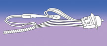
| Electric
Mirror Short Circuit |
Product
Safety Bulletin 03006A (May, 2003) explains that a fused jumper harness
(fig.16) may need to be added to the electric mirror switch of certain
1997-98 trucks. This harness addresses the possibility of a short circuit
in the mirror switch. See the bulletin for details.
All steps of the installation procedure must be done, and must be done
in the order given.
TIP: To avoid damaging the fusing circuit contained in the recall harness,
DO NOT connect the two-cavity connector until instructed to do so.
TIP: All terminals must lock into the connectors (check by lightly tugging),
and all terminal position assurance (TPA) locks must be properly installed.
TIP: All connectors must plug together with an audible click.
TIP: If the wires of the original harness or the jumper harness are crossed
(installed into the wrong cavities) when the jumper is installed, improper
operation will result. If the mirrors operate only with the headlamps
turned on, you’ve made a mistake.
-
Thanks to Dan Oden |
figure
16 |
| return
to Table of Contents |
|
| Rusty
Front Brake Rotors |
This
information pertains to 1999-2002 Sierra and Silverado 1500 Series
pickups only.
A new, more-aggressive front brake pad was released for both production
and service in the 2003 model year.
This new pad material has the ability to keep front rotor braking surfaces
clean and free of rust. These pads will also fit 1999-2002 1500 series
pickups.
If you are in an area of high corrosion (for instance, use of road salt)
and are replacing the front rotors due to flaking red rust, you might
want to install this new pad to help prevent a repeat occurrence. The
new pad kit part number is 18048101.
TIP: The new pads will not clean rotors that already have the flaking
red rust condition. Also, these pads should not be used on rear rotors.
-
Thanks to Steve Love |
| return
to Table of Contents |
|
| Oil
Life Monitor Addition |
Please
make the following addition to the Truck Oil Life Monitor article in
the June 2003 issue.
Trucks with DIC
2003 - 04 Sierra
2003 - 04 Sierra Denali
2003 - 04 Silverado
2003 - 04 Yukon, Yukon XL
2003 - 04 Tahoe, Suburban
2003 - 04 Escalade, Escalade EXT
2003 - 04 Avalanche
2003 - 04 Yukon Denali
2003 - 04 Hummer H2
1. Press the fuel information button until ENGINE OIL LIFE appears in
the display.
2. To reset the Oil Life System, press and hold the select button while
ENGINE OIL LIFE is displayed.
OIL LIFE RESET will appear on the display for 10 seconds to let you know
the system is reset.
-
Thanks to Jerry Garfield |
| return
to Table of Contents |
|
| Transmission
Stuck in Gear |
The
1997-2003 Corvette, or 1993-2002 Camaro and Pontiac Firebird equipped
with the 6 speed manual transmission may exhibit the following.
Primary Condition
- Unable to shift out of fourth gear.
Other Conditions
- 3-4 upshift -- hard shift, gear clash, or block-out.
- 4-3 downshift -- hard shift, gear clash or block-out.
- 2-3 upshift -- hard shift, gear clash or block-out.
- third gear hop-out
- fourth gear hop-out.
Replace the aluminum 3-4 shift fork with an iron 3-4 shift fork. The
part number of the iron shift fork as of July 9, 2003 is 88996653 and
is available only through GMSPO.
The 3-4 synchronizer and 3-4 blocking ring should also be replaced at
the same time.
-
Thanks to Mark Gordon |
| return
to Table of Contents |
|
| Belt
Chirp at Shutdown |
Owners
of some 2001-03 Chevrolet and GMC pickups and utilities with the 6.6L
LB7 diesel engine may experience the drive belt chirping on shut down.
This is a normal characteristic of all diesels, caused by the rapid stop
of the cranktrain due to higher compression, compared with a gasoline
engine.
The chirp may or may not occur, depending on variations in temperature,
humidity, engine compression, internal engine friction, belt condition,
tensioner spring tension, tensioner position at the time of engine stopping,
pulley condition, drag imposed by accessory drive components, where the
crankshaft is positioned when the engine is shut down, and any other
possible variables that affect how fast the engine comes to a stop and
variations on belt tension/friction.
For noises with the drive belt at any other time, such as while the engine
is running, refer to SI2000 documents:
677248 -- Drive belt chirping diagnosis
677250 -- Drive belt squeal diagnosis
677252 -- Drive belt whine diagnosis
677254 -- Drive belt rumbling diagnosis
-
Thanks to Jack McVoy |
| return
to Table of Contents |
|
| Aftermarket
Aircleaner |
Owners
of some 2003 Hummer H2s may experience lack or power, transmission
will not upshift, or an erratic shift or stumble.
TIP: Check for an aftermarket air cleaner installed on the vehicle.
Some aftermarket air cleaners pull air directly from the underhood area
of the vehicle at a higher temperature than the OEM airbox. The increase
in temperature can cause erroneous readings from the MAF sensor, causing
the above concerns. If an aftermarket air cleaner is discovered, reinstall
the OEM equipment and re-evaluate.
Follow all SI related diagnostics if an OEM air cleaner box is installed
and the vehicle still exhibits these conditions.
-
Thanks to Sean Garrison |
| return
to Table of Contents |
|
 Car
Issues – Fix It Right The First Time Car
Issues – Fix It Right The First Time |
Model
Year(s)
|
Vehicle
Line(s) --
Condition
|
Do
This
|
Don’t
Do This
|
Reference
Information / Bulletin
|
2001-2003
|
3800
L36 – Coolant Leak at Intake Manifold
|
Replace
the intermediate (upper) intake gasket
|
Replace
the intake manifold assembly
|
Bulletin
in process
VME to field 5/30/03
TechLink article in June
|
1998-2003
|
Seville – Rear
Seat HVAC Controls
|
Replace
the knob only
|
Replace
the entire rear seat blower switch assembly
|
03-01-39-001A
|
2000-2003
|
Cavalier/Sunfire/Grand
Am/Alero/Malibu – Inaccurate Fuel Gauge
|
Replace
sensor card for fuel gauge – accuracy issue
|
Replace
fuel sender/pump assembly
|
01-06-04-008D
|
1999-2003
|
Grand
Am/Alero – Window Disengagement, Broken Clips
|
Replace
sash clip only
|
Replace
door glass assembly
|
01-08-64-018
|
1997-2003
|
Grand
Am/Alero/Malibu – Brake Pulsation
|
Turn
rotor and brake align procedure
|
Replace
brake rotor for pulsation
|
00–05-23-002
01-05-23-001 (Know How Video #15040.01B)
|
2002-2003
|
Venture/Montana/Silhouette – Rear
Storage Compartment Link Arm Breaks
|
Replace
link arm
|
Replace
rear storage compartment
|
03-08-110-001
|
1997-2004
|
Century/Regal – HVAC
Operation, No “Auto” Light
|
Normal
in full heat or cold setting
|
Replace
HVAC control head for “Auto” light
|
99-01-39-007B
|
1999-2002
|
Corvette – Fuel
Gauge Intermittently Goes to Empty
|
Install
revised software
|
Replace
fuel senders or I/P cluster
|
02-06-04-010A
|
2003
|
All
cars with 4T40/45E, 4T56E and 4T80E – Code P0742
|
Replace
TCC PWM Solenoid
|
Replace
transmission or valve body assembly
|
02-07-30-039B
|
2002-2004
|
L61
EcoTech 4 Cylinder – Engine
|
Replace
Cylinder Bore Liner
|
Replace
Engine
|
03-06-01-018
|
|
| return
to Table of Contents |
|
|
 Truck
Issues – Fix It Right The First Time Truck
Issues – Fix It Right The First Time
|
Model
Year(s)
|
Vehicle
Line(s) --
Condition
|
Do
This
|
Don’t
Do This
|
Reference
Information / Bulletin
|
2003
|
Fullsize
Pickups and Utilities – Transfer Case Service Light
|
Replace
encoder motor sensor and reprogram TCCM
|
Replace
the module, encoder motor or transfer case for DTCs C0327,
P0836, P0500
|
03-04-21-001B
|
1999-2002
|
Fullsize
Pickups and Utilities – Throttle Body Sticks
|
Clean
throttle body adjust blade and insert plugs
|
Replace
throttle body
|
02-06-04-054B
|
2003
|
Fullsize
Pickups – 6.6L Diesel Engine ECM
|
Follow
SI and bulletins for proper diagnostics for P0181. Refer to
the Owner’s Manual (block heater and front cover)
|
Replace
ECM (DTCs P0540 and P0181) unless diagnostics confirm need
to replace
|
02-06-04-048,
03-06-04-021, 02-06-04-058 and parts restriction
|
2003
|
Silverado,
Sierra, Savana, Express > 8600 GVW – ABS Lamp On
|
Reflash
for code C0550
|
Replace
ABS module
|
03-05-25-003
and parts restriction
|
2002-2003
|
TrailBlazer,
TrailBlazer EXT – Wavy Front Fascia
|
Repair
fascia with Dual Lock
|
Replace
front fascia
|
02-08-62-004
|
2002-2003
|
All
TrailBlazers, All Envoys, Bravada – Mirror Erratic Return
|
Replace
mirror actuator and reprogram module
|
Replace
outside mirror assembly
|
02-08-64-008
02-08-64-021
|
1999-2003
|
Fullsize
and Midsize Utilities – Sunroof
|
Install
clip or mechanism kits. GMSPO has component parts.
|
Replace
sunroof
|
02-08-67-009
03-08-67-004
|
1999-2003
|
Fullsize
Pickups and Utilities, Midsize Utilities – Noise on Steering
|
Lube
I-Shaft
|
Replace
I-Shaft
|
00-02-35-003B
02-02-35-006A
|
2002-2003
|
TrailBlazer,
Envoy, Bravada without G67 – Moan/Boom
|
Replace
rear coil springs
|
Repurchase
vehicle for rear axle vibration/boom noise
|
02-03-09-002A
|
2002-2003
|
All
TrailBlazers, All Envoys, Bravada – Inoperative Tail
Light
|
Replace
tail lamp circuit board and bulb
|
Replace
rear tail lamp assembly for brake light
|
03-08-42-006
|
|
| return
to Table of Contents |
|
|
|
Know-How
Broadcasts for October
|
| |
 |
| Know-How
Broadcasts for October |
|
10270.10D
Emerging Issues
|
October
16, 2003
|
9:00
AM, 12:30 PM,
3:30 PM
Eastern Time
|
|
10270.22D
- New Model Features - 2004 Pontiac GTO
|
October
30, 2003
|
9:00
AM, 12:30 PM,
3:30 PM
Eastern Time
|
| -
Thanks to Tracy Timmerman |
|
|
| return
to Table of Contents |
| |
