|
 |
Note: Clicking
on any picture or illustration will open a larger version of that art.
|
|
Regulated
Voltage Control |
Basic Concept
and Benefits
Traditional charging systems use an internal temperature sensor inside
the generator to establish generator voltage set points. When the generator
is cold, it raises the voltage output set point. When the generator
is hot, it lowers the voltage output set point. This type of system
tends to overcharge the battery on long trips at highway speeds and
undercharge the battery on short trips with low vehicle speeds.
Regulated Voltage Control (RVC) is a new dynamic control of the vehicle’s
system voltage (fig. 1). It regulates the
generator’s output voltage, based mainly on estimated battery
temperature and battery state-of-charge. The main benefits of this system
are:
- Improved fuel economy
- Extended battery life
- Extended lamp life
- Extended switch life
There are two types of RVC systems used today -- integrated RVC and
stand-alone RVC (SARVC).
Integrated systems uses a battery current sensor to provide a body controller
(BCM) the amount the battery is charging or discharging. Accurate voltage
measurements are taken through the battery positive voltage and ignition
1-voltage circuits. The BCM then communicates information over serial
data circuits for the ECM/PCM to directly control the generator.
SARVC systems do not use the BCM for operation. They have a generator
battery control module mounted to the negative battery cable, to interpret
battery current, and voltage and battery temperature inputs. The battery
current sensor is internal to the module. This module also directly
controls the generator L-terminal duty cycle instead of the ECM/PCM.
Both types of system have two types of corrective actions to insure
the battery stays at an 80% state of charge. These include up to three
levels of load shed and up to three levels of idle boost operation.
Refer to the service manual Description and Operation for load shed
and idle boost.
We will discuss the basic operation of the RVC system, the three different
generations of systems used today on GM vehicles, components used on
each separate system and a general diagnostic information section.
System Operation
Not all systems will enter all modes of operation; refer to the applicable
service manual for exact Description and Operation.
The purpose of the RVC system is to maintain the battery state-of-charge
at 80% or above and support vehicle loads.
The six modes of operation include:
- Charge Mode
- Fuel Economy Mode
- Voltage Reduction Mode
- Start Up Mode
- Windshield Deice Mode
- Battery Sulfation Mode
The PCM/ECM (generator battery control module on full-size trucks) controls
the generator through the generator L-terminal control circuit. It monitors
the generator performance though the generator field duty cycle signal
circuit. The signal is a 5 volt PWM (pulse width modulated) signal of
128 Hz with a duty cycle of 0-100%. Normal duty cycle is between 5-95%.
The ranges between 0-5% and 95-100% are for diagnostic purposes. The
following table shows the commanded duty cycle and output voltage of
the generator:
| Duty
Cycle |
Generator
Voltage
Set Point |
| 10% |
11.0V |
| 20% |
11.56V |
| 30% |
12.12V |
| 40% |
12.68V |
| 50% |
13.25V |
| 60% |
13.81V |
| 70% |
14.37V |
| 80% |
14.94V |
| 90% |
15.5V |
The generator provides
a feedback signal of the generator load through the generator field
duty cycle signal circuit to the control module. The signal is a 5 volt
PWM signal of 128 Hz, with a duty cycle of 0-100%. Normal duty cycle
is between 5-99%. The ranges between 0-5% and 100% are for diagnostic
purposes.
Charge Mode -- The control module enters Charge Mode
whenever one of the following conditions is met:
- Under WOT conditions and when the fuel rate (sent by the ECM/PCM)
is greater than 21 g/s and the throttle position is greater than 90%.
- The headlamps are ON, low or high beam.
- The wipers are ON for more than 8 seconds.
- The electric cooling fans are ON high speed.
- The rear defogger is ON.
- The Battery SOC (state of charge) is less than 80%.
When one of these conditions is met, the control module ramps up the
voltage slowly to a level between 13.4 to 15.5 volts (depending upon
the mode of operation the system is presently in) at a rate of 8 mV
to 50 mV per second.
Fuel Economy Mode -- The control module enters Fuel
Economy Mode when the following conditions are met:
- The calculated ambient air temperature is above 0°C (32°F).
- The calculated battery current is less than 15 amperes and greater
than -8 amperes.
- The battery state of charge is greater than 80%.
- The generator field duty cycle is less than 99%.
Its targeted generator output voltage is 13.0 volts. The control module
will exit this mode once the criteria are met for Charge Mode.
Voltage Reduction Mode -- The control module will enter
Voltage Reduction Mode when the following conditions are met:
- The calculated ambient air temperature is above 0°C (32°F).
- The calculated battery current is less than 2 amperes and greater
than -7 amperes.
- The generator field duty cycle is less than 99%.
Its targeted generator output voltage is 12.9 volts. The control module
will exit this mode once the criteria are met for Charge Mode.
Start Up Mode -- After the engine has started, the
control module sets a targeted generator output voltage of 14.5 volts
for 30 seconds.
Battery Sulfation Mode -- The control module enters
this mode when the battery voltage is less than 13.2 volts for 45 minutes.
Once in this mode, the generator battery control module will set a targeted
output voltage between 13.9 to 15.5 volts for 5 minutes. The control
module will then determine which mode to enter depending on voltage
requirements.
RVC Mode -- The control module bases the charging voltage
on battery state of charge (SOC). Battery SOC is estimated during a
key off event every 8 hours, after 3 voltage measurements every 24 hours
thereafter, and then monitored constantly while the ignition is on.
These measurements of voltage are then compared to estimated battery
temperature, as battery temperature vs. battery voltage directly corresponds
to battery SOC. While the engine is running, the system uses both the
battery voltage and estimated battery temperature to determine the battery
current in and out of the battery. The control module then regulates
the charging voltage to keep the battery above an 80% SOC.
| Vehicles |
System
Generation |
Modes
of Operation |
Key
Components |
| 2004 Cadillac
CTS |
Generation
II |
RVC Mode |
DIM, PCM |
| 2004 Cadillac
SRX |
Generation
II |
RVC Mode |
DIM, ECM |
| 2005 Cadillac
STS |
Generation
III |
Charge Mode
and Voltage Reduction Mode |
Battery Current
Sensor, IPM, ECM |
| 2005 Full Size
Pick and Utilities under 8600 GVW |
Generation
IV |
Charge Mode,
Fuel Economy Mode, Voltage Reduction Mode, Start Up Mode, Battery
Sulfation Mode |
Generator Battery
Control Module, ECM/PCM |
| 2005 Chevrolet
Cobalt |
Generation
IV |
Charge Mode,
Fuel Economy Mode, Voltage Reduction Mode, Start Up Mode, Battery
Sulfation Mode |
Battery Current
Sensor, BCM, ECM/PCM |
| 2005 Buick
LaCrosse |
Generation
IV |
Charge Mode,
Fuel Economy Mode, Voltage Reduction Mode, Start Up Mode, Battery
Sulfation Mode |
Battery Current
Sensor, BCM, ECM/PCM |
| 2005 Pontiac
Grand Prix and Grand Prix GXP |
Generation
IV |
Charge Mode,
Fuel Economy Mode, Voltage Reduction Mode, Start Up Mode, Battery
Sulfation Mode |
Battery Current
Sensor, BCM, PCM |
| 2005 Chevrolet
Uplander, Pontiac Montana, Buick Terazza |
Generation
IV |
Charge Mode,
Fuel Economy Mode, Voltage Reduction Mode, Start Up Mode, Battery
Sulfation Mode |
Battery Current
Sensor, BCM, PCM |
Components
Battery Current Sensor -- Battery Current Sensor -- The battery
current sensor is a serviceable component that is connected to the negative
battery cable at the battery. The battery current sensor is a 3-wire
Hall-effect current sensor. The battery current sensor monitors the
battery current. It directly inputs to the BCM. It creates a 5 volt
PWM signal of 128 Hz with a duty cycle of 0-100%. Normal duty cycle
is between 5-95%. The ranges between 0-5% and 95-100% are for diagnostic
purposes.
Body Control Module (BCM), Instrument Panel Module (IPM) and
Dash Integration Module (DIM) -- The BCM determines the output
of the generator and sends the information to the ECM/PCM for control
of the generator L-terminal control circuit. It monitors the generator
field duty cycle signal circuit information sent from the ECM/PCM that
determines the generator electrical load. It monitors the battery current
sensor, the battery positive voltage circuit, and estimated battery
temperature to determine battery state of charge (SOC). The BCM performs,
or sends, commands to ECM or other controllers to perform idle boost
and load management operations.
ECM/PCM -- The ECM/PCM directly controls the generator field
control circuit input to the generator. The ECM/PCM receives control
decisions based on messages from the BCM/IPM. It monitors the generator
field duty cycle signal circuit and sends the information to the BCM/IPM.
On some vehicles, the ECM/PCM overrides the control decision of the
BCM/PCM when the following conditions are met:
- The engine cooling fans are ON high speed.
- There is a high fuel demand.
- The calculated ambient air temperature is less that 0°C (32°F).
Instrument Panel Cluster (IPC) -- The IPC provides
a means of driver notification in case of a charging system failure.
Refer to the service manual for exact operation.
Generator Battery Control Module -- It communicates
with the PCM, IPC and BCM for RVC operation. It is a serviceable component
that is connected to the negative battery cable at the battery. It directly
controls the generator field control circuit input to the generator.
It monitors the generator field duty cycle signal circuit, its internal
battery current sensor, the battery positive voltage circuit, and estimated
battery temperature to determine battery state of charge (SOC).
Diagnostics
Diagnostics are specific for each vehicle that uses this system. Refer
to the applicable service manual for DTC information.
For L-terminal diagnostics, set your DVOM to monitor frequency. When
the system is operating normally, you should read a duty cycle of 5-95%
depending on which mode the system is in and also the battery SOC. The
5-volt reference signal for the PWM signal is provided by the generator
and cycled to ground by the ECM/PCM or generator battery control module,
depending on the system.
For F-terminal diagnostics, set your DVOM to monitor frequency. When
system is operating normally, you should read a duty cycle of 5-99%
depending on which mode the system is in and also the battery SOC. The
ECM/PCM or generator battery control module, depending on the system,
provides the 5-volt reference signal for the PWM signal and is cycled
to ground by the generator.
The Tech 2 may include some of the following parameters:
- ECM/PCM
- Generator L-Terminal
- Generator F-Terminal
- Battery Voltage
- BCM/DIM/IPM
- Battery Current Sensor
- Battery Voltage
- Ignition Voltage
- Load Shed Level
- Idle Boost Level
The generator battery control module incorporates most of the scan tool
parameters, except load shed and idle boost, as this system does not
take corrective actions.
If you feel there is a charging system error, first check for related
charging system and low voltage DTCs set in the control module.
TIP: Diagnose
P codes first, as these DTC will set if there is a generator or control
circuit failure.
If no DTCs are present, refer to the Charging System test in the service
manual. If this test does not present a failure, you may need to test
drive the vehicle and monitor the idle boost and load shed parameters.
This may lead you to some type of high load condition that may be normal;
compare to a known-good vehicle.
- Thanks to Jim Mauney and John Spidle |
|
figure
1 |
|
|
| return
to Table of Contents |
|
|
| Tech
2 Diagnostic Pathing Cards |
GM Service Operations announces the latest revision of the Tech 2 pathing
cards. These handy pocket-sized reference cards (Body, Chassis and Powertrain)
help you make the most of your Tech 2 diagnostic tool (fig.
2).
The cards cover model year 1992 through the present.
Simply select the item(s) you are looking for from the alphabetized
list, then follow the “path” provided. In most cases, you
will be selecting from the numerous data and input/output controls in
the Diagnostic Menu.
GM dealers will automatically receive two each of the
pathing cards at no charge. Individual cards and sets may be purchased
from the DWD Online Store.
Go to www.gm-dealerworld.com.
You will need your ID and password for access. Then click on the DWD
Store button in the upper left corner. The most direct way to locate
the item is to use Search and the item number. See the table below.
Non-dealers may purchase sets of three pathing cards
from the ACDelco online store.
Go to: http://www.acdelcotechconnect.com
and click the Training tab. Click the ACDelco Online Store link. Then
click Manuals and scroll to locate the desired item.
Functional Diagnostic Guide
A Functional Diagnostic Guide is available separately. Also pocket-sized,
this handy reference card uses the “Service Category” style
menu logic as found in SI. It will help you quickly locate items such
as data and input/output controls on your Tech 2. It’s a must
for anyone performing diagnostic procedures on current and future GM
vehicles utilizing GM LAN and Class 2 protocols.
- Thanks to Mark Stesney and Roger
Kneip
Item |
Item
Number from
DWD
|
Item
Number from
ACDelco
|
| Body Card |
ROM00173 |
- |
| Chassis Card |
ROM00174 |
- |
| Powertrain
Card |
ROM00175 |
- |
Set of cards
which includes:
ROM00173,
ROM00174 and
ROM00175
|
ROM00190 |
ROM00190 |
| Functional
Diagnostic Guide |
ROM00164 |
ROM00164 |
|
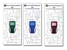
figure 2 |
| |
|
|
Correct Service Part Number for Equinox ECM |
There
has been some confusion regarding the proper service part number for
the ECM for the 2005 Equinox. Some improper part numbers were listed
on labels and in the parts system. These have been corrected. See the
accompanying table.
All of the electronic information has been corrected and will indicate
the correct service part number to order. The service CD correctly identifies
the utility file that is used to flash the Equinox.
- Thanks to John Fletcher and Craig
Jones
Service
Part Number |
Usage |
12581598 |
will
NOT work |
12591027 |
will
work fine |
12591279 |
will
work fine |
|
|
return to Table of Contents |
|
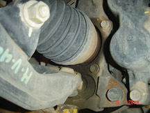
| Front
Hub Bearing Grease Leak |
On
the 2004-05 Chevrolet HD Silverado, GMC HD Sierra, and Hummer H2, the
front hub bearing assembly may be unnecessarily replaced for leaking
grease. This condition may be normal (fig. 3).
The hub bearing assembly contains 15% more grease at assembly than necessary,
to ensure adequate bearing performance. The additional grease will build
up on the seal, which acts as an additional barrier against contamination.
This is normal grease purge, and no repair is necessary.
TIP: Refer to
the wheel bearing diagnosis in SI if the integrity of the bearing is
questionable. Replace the bearing assembly only for noise or excess
end play.
-
Thanks to Steve Love and Dan Stress |
| 
figure
3
|
| return
to Table of Contents |
|
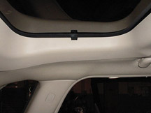
| Malibu
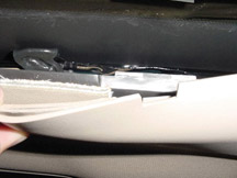
Maxx Rear Sunshade |
This information pertains to 2004 Chevrolet Malibu Maxx.
Some customers may comment that the rear sunshade (fig.4)
comes unhooked from the rear sunroof trim and snaps shut. This may be
caused by wind buffeting from driving with the windows open, vibration
from driving over rough roads or solar exposure causing the rear sunroof
trim to soften and deform.
To correct this condition, install reinforcement 15227088 on the left
and right sides of the rear sunroof trim.
1. Remove any adhesive or foreign material from the back side of the
rear sunroof trim in the area where the reinforcement will be installed.
2. Clean the back side of the trim with isopropyl alcohol and allow
to dry.
3. Remove the protective backing from the reinforcement, pull back the
left side of the rear sunroof trim and carefully apply the reinforcement
to the back side of the rear sunroof trim (fig.
5).
TIP: Align the
slot in the reinforcement with the slot in the rear sunroof trim.
4. Repeat steps 1-3 for the right side.
Watch for a future bulletin.
- Thanks to Joel Ebner |
figure
4 |
figure
5 |
| return
to Table of Contents |
|
| Unique
Features of CTS-V |
Bulletin
04-00-89-027 has being released to inform dealers of the unique features
of the Cadillac CTS-V (fig. 6). Here are
highlights.
Stiff Ride
The CTS-V has a noticeably stiffer suspension than the CTS. Those with
traditional Cadillac expectations may not find this feature appealing.
Rear Axle Hop
In extreme loss of drive wheel traction or abusive applications of power,
the independent 5-link rear suspension will exhibit an abrupt wheel/axle
hop.
Handling in Snow
The P245/45WR18 Extended Mobility Tires (EMT, or run-flat) tires provide
the ultimate handling for the combination street and track environment.
They will not give optimum performance in mud or snow.
Brake Dust
A key requirement of the Brembo high performance brake lining is to
dissipate heat from the braking system, resisting fade, cooling rotors
and preventing brake fluid boil. A by-product of heat dissipation is
brake dust accumulation on wheel faces.
Brake Bind After Sitting
The Brembo brake components have a normal tendency to a light bind,
often noted as resistance, then a light clunk when attempting to move
the vehicle forward or rearward after a cold soak.
Critical Tire Pressure Monitor
The factory fill is 38 psi (260 kPa), to ensure proper bead sealing
and to prevent tire damage in tied-down shipping. If not adjusted to
the specified 30 psi (210 kPa), a warmed up tire will easily exceed
the 42 psi (290 kPa) limit on the TPM. Excessive pressures will also
turn an already very stiff ride into a harsh, poor-handling experience.
Rough Idle
A key element of the 400 horsepower LS6 V8 engine is better breathing
ability through unique valve lift and duration. A normal result of this
camshaft design is an unstable idle or random roughness.
1-4 Skip Shift
To help achieve the best possible fuel economy, the transmission forces
a 1st to 4th shift under the following conditions:
- coolant temperature above 169°F (76°C)
- vehicle speed 15-19 mph (24-31 km/h)
- throttle at 21% or less
The 1-4 indicator in the DIC is only momentary.
Driveline Clunk on Declutch in Parade Type Driving
A clunk-clunk noise from the driveline may be heard when depressing
and releasing the clutch pedal or between shifts while driving in a
steady, slow speed parade-type situation. This is a normal characteristic
of the driveline.
Oil Life Monitor and Mobil-1 Oil
Oils other than Mobil-1 (factory fill) may be used as long as they meet
GM Standard GM4718M. Oil life may seem shorter on the CTS-V than other
Cadillac vehicles because the OLM algorithm uses factors of engine RPM
and coolant temperature cycles, both of which the CTS-V will experience
in greater fluctuations.
Navigation But No Voice Commands
Because the steering wheel controls are for the I/P DIC, traction control,
and cruise control, there are no re-configurable controls, OnStar®
interface or voice command controls. Voice command is unavailable on
the CTS-V.
Memory Functions
Because the CTS-V has a manual transmission, the driver 1 and 2 seat
and mirror memory functions operate only when the parking brake is set,
whether the driver uses the RKE or the 1 and 2 buttons on the driver's
door panel.
G-Force Meter
A lateral accelerometer display located below the tachometer can be
accessed using the outermost rocker switch on the left steering wheel
spoke. To reset, press and hold the rocker switch while the G-force
meter is displayed.
-
Thanks to Brian Combs |

figure
6 |
| |
| |
|
return
to Table of Contents |
|
| Noisy
Blower Motor |
According to bulletin 04-01-39-005, owners of some 2004 Buick LeSabre
and Pontiac Bonneville models may comment on a noisy HVAC (heating,
ventilation and air conditioning) blower motor. Others may comment that
the blower motor emits a low-pitch hum.
Cadillac DeVille and Seville are covered in bulletin 03-01-37-001.
TIP: Although
the bulletins mention 2004 only, the fix applies to 2002-03 as well.
Install a new blower motor 89018521. For replacement instructions, refer
to the Blower Motor Replacement procedure in the Heating, Ventilation
and Air Conditioning section of SI.
Refer to figure 7 for a comparison. The
old blower motor is on the left and the new motor is on the right.
Parts are currently available from GMSPO.
-
Thanks to Bill Metoyer and Ed Kern
Part
Number |
Description |
Quantity |
89018521 |
Motor,
Blower (with impeller) |
1 |
|
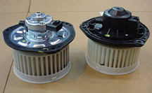
figure
7 |
|
return
to Table of Contents |
|
| Tire
Pressure Sensor Learn |
Owners
of some 2000-04 DeVilles and Sevilles may comment on a SERVICE TIRE
MONITOR message being displayed through the DIC. In this case, follow
the diagnostic procedures outlined in SI. If no TPM system components
were replaced and normal TPM system operation was restored by performing
the tire pressure sensor learn procedure only, use labor operation E0715.
Labor operation E0715 has been established for those repairs deemed
warrantable. For warranty repairs, refer to Service Bulletin 04-03-16-001
for detailed information.
TIP: E0715 is
not to be used with RCDLR replacement, or sensor replacement op codes.
The labor ops for the procedure already include time for “learning”
the sensors.
TIP: Performing
the tire pressure sensor learn procedure due to customary maintenance
items (such as tire rotation) are not warrantable.
- Thanks to Bill Denton |
| |
| return
to Table of Contents |
|
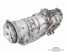
| Operating
Characteristics of 5L40E/5L50E Transmissions |
The
Hydra-Matic 5L40E/50E automatic transmissions have some unique operating
characteristics that customers may not be familiar with. (fig.
8 5L40E, fig. 9 5L50E, fig. 10 5L50E XLR) They have been designed
to provide more of a manual transmission feel than other Hydra-Matic
automatic transmissions.
These transmissions are used in 2004-05 Cadillac CTS, SRX, STS, and
XLR as indicated in the accompanying table. Here are descriptions of
the unique operating characteristics.
Normal Mode Operation (CTS, SRX, STS, XLR) -- During
normal mode operation, drivers may notice increased powertrain braking
after releasing the accelerator pedal. The vehicle will not coast freely
when the accelerator pedal is released but will start to gradually slow
down as if the brakes were lightly applied. This feels very similar
to releasing the accelerator pedal on a vehicle equipped with a manual
transmission.
Sport Mode Operation (CTS, SRX, STS) -- Typically,
Sport mode delays upshifts. The Sport mode simulates the performance
driving of a manual transmission. Under certain conditions, the vehicle
will maintain specific gears longer than a traditional automatic would.
When driving in Normal mode in 5th gear, depressing the Sport button
causes an immediate 5-4 downshift, which will be maintained for ten
seconds. In any other gear, no downshift takes place when Sport is engaged.
In Sport mode, the vehicle has firmer shifting and increased performance,
and the transmission may remain in a gear longer than it would in Normal
mode.
Driver Shift Control (DSC) (SRX, STS, XLR) -- The driver
manually overrides the automatic gear selection. Various mechanization
options for input device and degree of override allowed.
Performance Algorithm Shifting (PAS) (XLR, 2004 SRX) --
Override of usual automatic gear selection during closed throttle high
lateral acceleration maneuver. Lower gear is accompanied by near synchronous
engine speed control for quick response upon re-opening throttle (enable
threshold bias in Sport mode).
TIP: On SRX, this feature
is enabled in Sport. On XLR, it is always enabled.
Performance Algorithm Liftfoot (PAL) (CTS, SRX, STS, XLR) --
Prevents liftfoot upshifts while maintaining engine braking during repeated
aggressive cornering.
Winter Mode (CTS) -- The vehicle launches in 2nd or
3rd gear instead of 1st, to avoid wheel spin in snow or ice, if selected
by the driver.
Shift Stabilization (CTS, SRX, STS, XLR) -- Shift stabilization
is used to minimize shift busyness, or hunting between ranges. Based
on several inputs and a map of engine torque at various RPM and throttle
position, the TCM determines before making an upshift whether the engine
will be able to maintain vehicle speed in the next higher range. If
it calculates that it cannot maintain speed, it will prevent the upshift
from occurring.
Downgrade Detection Brake Assist (CTS, SRX, STS, XLR) --
Shift to lower gear with braking on downgrade based on fuzzy logic rules
calculated from a thermal brake model, terrain detection, desired acceleration,
vehicle speed, and mass detection.
Adapts (CTS, SRX, STS, XLR) -- Continual comparison
of actual shift times to desired shift times. The transmission controls
make hydraulic adjustments to assure the actual shift times approach
the ideal shift time the next time the shift is made for similar operating
conditions of vehicle rpm, engine load, and road load conditions. The
adaptive shift process continues for the life of the vehicle, to provide
consistent and optimized shifts.
- Thanks to Robert Martin and Chris Anderson
- |
2004-05
CTS
|
2004-05
SRX
|
2005
STS
|
2004-05
XLR |
Transmission |
5L40E |
5L40E/50E |
5L40E/50E |
5L50E |
Normal
Mode Operation |
X |
X |
X |
X |
Sport
Mode Operation |
X |
X |
X |
- |
Driver
Shift Control |
- |
X |
X |
X |
Performance
Algorithm
Shifting
|
- |
X
(2004 only)
|
- |
X |
Performance
Algorithm
Liftfoot
|
X |
X |
X |
X |
Winter
Mode |
X |
- |
- |
- |
Shift
Stabilization |
X |
X |
X |
X |
Downgrade
Detection Brake Assist |
X |
X |
X |
X |
Adapts |
X |
X |
X |
X |
|
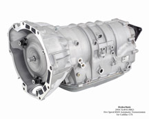
figure
8 |
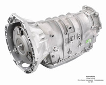
figure
9 |
figure
10 |
| return
to Table of Contents |
|
| HVAC
Module Service |
This information applies to the 2004 Cadillac XLR and the 2005 Chevrolet
Corvette and newer.
Use special care when removing or installing the HVAC module for service.
The HVAC module is seated between a non-removable upper and lower tie
bar
(fig. 11). The HVAC module must be partially
disassembled before removal and installation (fig.
12).
Refer to SI 2000 to obtain the service procedure for correctly removing
and installing the HVAC module. Failure to do could result in damage
to the HVAC module.
-
Thanks to Chris Semanisin |
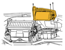
figure
11 |
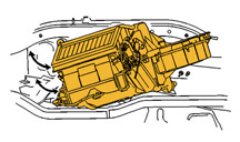
figure
12 |
|
return
to Table of Contents |
|
| Duramax
Diesel 6.6L Diagnostic Tips (Changes) |
Here are some diagnostic tips you may find useful when diagnosing driveability
concerns on the Duramax 6.6L diesel engine. This information
replaces the July 2001 Techlink article on Duramax Diagnostic Tips.
Misfire
If there is a misfire code, or a misfire can be detected during operation,
connect the Tech 2. Look on the Engine Data 2 list to find the Balancing
Rates for the cylinders. Do not use Balancing Rates to diagnose
symptoms that do not occur at idle. Use the fuel Injector Balance Test
with Tech 2 to diagnose symptoms at higher engine and vehicle speeds.
Balancing Rates
Normal fuel delivery to each cylinder is around 1 cubic millimeter (mm3)
for the pilot injection and 7 mm3 for the main injection. The balancing
rates are the measurements of the amount of fuel removed from or added
to these normal fuel quantities during each combustion event.
Balancing rates are available and accurate only during stable idle.
These numbers tell you whether or not you have a possible compression,
injector control, or injector issue.
Once the misfire is detected, the balancing rate of the cylinder that
has the misfire will be as high as 15 mm3. The misfire codes (P0300,
P0301-P0308) will set only after the first 90 seconds on Federal LB7s
(30 seconds on California LB7) of engine operation and will set only
when the balancing rate goes above 15 mm3.
The normal values that should be seen on the balancing rate parameters
will range between -4.0 and +4.0 in Neutral or Park (-6.0 to +6.0 in
Drive when the brake is fully applied). Suspect a possible problem when
the balancing rate of a particular cylinder starts to increase out of
the normal operating range. An example of a possible problem cylinder
would be a balancing rate of 7 mm3 or so. Once the numbers start to
increase out of the normal range, the cylinder is progressively contributing
less power than the other cylinders.
Diagnosing "Fuel Knock"
Perform the diagnostics listed in the Fuel Knock symptom table.
Vacuum/Pressure Gauge
The vacuum/pressure gauge is also useful when diagnosing the Duramax
6.6L diesel (fig. 13). In the case of a
complaint of “starts, runs, then dies,” or if the vehicle
will not start after sitting for a period of 30 minutes or longer, hook
up the vacuum/pressure gauge to the Schraeder valve on the right front
valve cover to determine if air intrusion into the fuel system is the
root cause of the complaint. With the vacuum/pressure gauge hooked up,
prime the fuel manager until 10 psi is reached. If pressure does not
reach 10 psi after twenty or so pumps, air intrusion is the cause. Refer
to the fuel system diagnostic in the manual.
In the case of a “cranks, no start” condition, use the Tech
2 to check for codes. If no codes are present, use the vacuum/pressure
gauge to check the fuel supply system vacuum to the pump while cranking.
If the vacuum increase to more than 5 in. Hg, there is a restriction
in the fuel system between the fuel tank and the high pressure pump.
If the vacuum is ok, ensure that pressure is being made under Engine
Data 1, looking at Actual Fuel pressure.
Observe the Engine Cranks but Does Not Run Diagnostic and follow the
guidelines provided in order to determine if the pump or the fuel injectors
are the problem.
-
Thanks to William Smithers |
| |
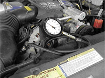
figure
13 |
|
return
to Table of Contents |
|
| A/C
Low Pressure Switch Diagnosis |
The
A/C low pressure switch open/close pressure switch point cannot be accurately
determined by measuring pressure at the low side service port on 1999-2005
C/K trucks and 2003-05 Hummer H2.
Because the evaporator is between the low side service port and the
A/C low pressure switch, pressures measured at the port may not be the
same as those at the switch. This difference can cause misdiagnosis
of switch operation.
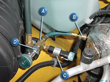
A new bulletin 04-01-38-010 details the use of a new A/C diagnostic
tool GE-47742, available from SPX Kent-Moore. Here are the highlights.
GE-47742 allows you to monitor the actual pressures at which the switch
opens and closes in the vehicle’s refrigerant system. The tool
is a three-way T-fitting.
With the switch removed from the accumulator, the switch installs into
the GE-47742 tool. The tool installs in place of the switch in the accumulator.
Finally, the low side gauge of the ACR2000 connects to the service port
on the tool.
The tool installation is shown in figure 14:
A - GE-47742
B - Connection to accumulator
C - Low pressure switch
D - ACR2000 low side gauge hose
IMPORTANT: Before
plugging in the switch wire harness, temporarily remove the seal from
the connector. The “plunger effect” of plugging the sealed
connector into the switch induces a 5-10 psig (35-69 kPa) pressure on
the back side of the switch. This pressure will skew the opening/closing
characteristics of the switch as much as 5-10 psi (35-69 kPa) until
the pressure bleeds off, which can take 20 minutes or longer.
Operate the A/C system under the following conditions:
- Engine (On)
- 1500 RPM
- A/C (On)
- Blower (Low)
- Aux Blower (Low)
- Temperature (Full Cold)
- Aux Temp (Full Cold)
- Inside air/Re-circ
- No sun load (in the shade)
Use the Tech 2 to determine the low pressure switch status and the ACR2000
to determine low side pressure.
The Tech 2 displays switch status as “Normal” for Closed
and “Low Pressure” for Open.
A properly operating switch should open between 20-25 psi (138-172 kPa)
and close between 40-46 psi (275-317 kPa).
IMPORTANT: Remember
to install the seal onto the A/C low pressure switch connector when
the diagnosis is complete.
- Thanks to Frank Rogers and Steve Love |
| |
figure
14 |
|
return
to Table of Contents |
|
| Tire
Pressure Monitor Diagnostic Tool |
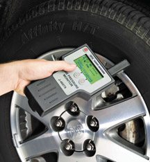
A
new essential diagnostic tool J-46079 for Tire Pressure Monitor Systems
(TPMS) is now being shipped to dealers (fig. 15).
It works on all GM vehicles equipped with Radio Frequency (RF) Direct
Sense TPM systems.
These TPM systems consists of an RF-transmitting pressure sensor inside
each tire/wheel assembly and a receiver inside the vehicle. The pressure
sensor transmits an RF signal, and the receiver interprets the signal.
The diagnostic tool completely tests the TPM system.
To verify the sensors can transmit valid data with good signal strength
in response to a low frequency or magnetic activation, J-46079 TPM Tester
receives the RF signal from the sensor and displays the sensor’s
transmitted data (tire pressure, sensor ID number, sensor mode) on the
tester’s LCD screen.
TIP: The tool
cannot determine if the sensor internal roll switch is functioning.
For that, a test drive is necessary.
To confirm the operation of the vehicle’s receiver, J-46079 TPM
Tester transmits four simulated sensor signals to the receiver. Once
the vehicle receives the signals from J-46079 TPM Tester, the simulated
data (tire pressure, ID number and sensor mode) can be viewed accessing
the module data with a Tech 2 scan tool.
TIP: On
some vehicles, only the tire pressure can be viewed on the scan tool.
J-46079 TPM Tester can also be used on some vehicles when performing
the sensor learn procedure after tire rotation. This simplifies and
speeds up the procedure.
This tool is simple and easy to use and assures that the tire pressure
monitor system is functioning properly. For more information on the
J-46079 Tire Pressure Monitor Tester, contact Kent-Moore at 1.800.345.2233.
- Thanks to Mike Banar and Scott Bower |
|
figure
15 |
| return
to Table of Contents |
|
| 4T65E
Valve Body |
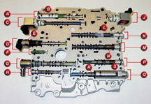
A
recently released bulletin 02-07-30-013B refers to 2001-04 vehicles
with 4T65E automatic transmission (RPOs M15, MN3, MN7, M76). The bulletin
refers to various transmission conditions, including incorrect shifts,
poor performance, harsh upshifts, slipping, TCC stuck on or off and
various DTCs. The bulletin relates all of these conditions to debris
in the valve body and case oil passages.
Refer to the bulletin for details.
Figure 16 is a color photo of a valve body
cutaway, to show you the actual locations of various bores, items and
functions mentioned in the bulletin.
- Thanks to Darryl Butler
ID |
Bore
No.
|
Item
Name |
Function |
A |
1 |
Pressure
Regulator |
- |
B |
1 |
- |
Reverse
Boost Valve inside bushing |
C |
2 |
1-2
Shift Valve Solenoid A |
- |
D |
4 |
Torque
Signal Valve |
- |
E |
4 |
- |
Pressure
Control Solenoid |
F |
5 |
Pressure
Relief |
- |
G |
6 |
PWM
and TCC Control |
- |
H |
7 |
TCC
Regulator Apply |
- |
J |
16 |
Solenoid
B |
- |
K |
11 |
3-4
Shift Valve |
- |
L |
11 |
- |
4-3
Manual Downshift |
M |
12 |
2-3
Shift Valve |
- |
N |
12 |
- |
3-2
Manual Downshift |
P |
14 |
Secondary
1-2 Accum |
- |
Q |
15 |
- |
- |
R |
15 |
2-3
Accumulator Valve |
- |
S |
15 |
3-4
Accumulator Valve |
- |
|
figure
16 |
| return
to Table of Contents |
|
| Quick
Upshifts |
Some
1993-2005 light duty trucks and utilities may experience quick upshifts
and be in fourth gear with the TCC applied by 20 mph. Sometimes DTC
P1875 may accompany the concern. The owner may also describe the condition
as a lack of power, chuggle, miss, shake, or surge. This condition can
also occur on 2WD models.
The ECM, PCM, or VCM may believe that the Transfer Case is in 4low and
change the shift pattern accordingly. Use the Tech1/Tech2 to verify
the status of the 4low input. If the 4low input status is YES or ENABLED
with the Transfer Case in 2wd or 4wd High or if this is a 2wd vehicle,
the 4low signal circuit is shorted to ground. Or the TCCM and or ECM,
PCM, or VCM is taking the circuit to ground.
1. Disconnect the TCCM if equipped. If the concern goes away, replace
the TCCM. If the concern is still present, go to step 2.
2. Remove the 4low signal circuit from ECM, PCM, or VCM connector. If
the concern goes away, inspect the 4low signal circuit for being shorted
to ground. If concern is still present with the 4low signal circuit
removed from ECM, PCM, or VCM connector, replace the ECM, PCM, or VCM.
-
Thanks to Rusty Sampsel |
| return
to Table of Contents |
|
| Theater
Lighting |
Some
owners of the 2005 Chevrolet Equinox may comment that the interior lights
will not theater dim.
This is normal operation. The interior lights on Equinox do not theater
dim. The service information and the owner’s manual will be updated
to reflect the correct operation of the interior lights.
- Thanks to Chuck Krepp |
|
|
|
return
to Table of Contents |
|
| Clutch
Pedal Squeak |
On
some 2001-03 Chevrolet Silverado and GMC Sierras with ML6 Manual Transmission,
the clutch pedal may squeak. The condition typically occurs during hot
ambient temperature.
Replace the clutch pedal assembly with part number 15120866.
-
Thanks to Rusty Sampsel |
|
|
| return
to Table of Contents |
|
| Axle Water
Contamination |
Some
2001-04 Chevrolet S-10 and GMC Sonoma 4- Door Pickups may experience
water contamination inside the rear axle.
Inspect the location of the rear axle vent hose to see if it is positioned
in a location that is directly below the gap between the cab and the
bed. If so, relocate the vent hose to a new location that will prevent
rain water from entering the vent hose.
-
Thanks to Rusty Sampsel |
| return
to Table of Contents |
|
| Chafed
Wires |
Some
2005 Chevrolet Equinoxes may exhibit power mirrors inoperative, seat
belt warning light on, no audio/poor audio and/or various class 2 communication
faults.
During assembly of the lower A-pillar trim or kick panel, the clip on
the trim panel has chafed the wire(s), resulting in a short to ground
or an open fuse. The C204 connector contains circuits for ignition 1,
power mirrors, seatbelt warning, audio speakers and class 2 communication.
Remove the lower left trim panel, inspect for any chafed wires near
the C204 connector and repair as necessary. Reroute the harness to prevent
future contact.
-
Thanks to Chuck Krepp |
|
|
| return
to Table of Contents |
|
 Car Issues – Fix It Right The First Time
 |
Model
Year(s) |
Vehicle
Line(s) --
Condition |
Do
This |
Don’t
Do This |
Reference
Information / Bulletin |
2004 |
Grand
Prix – Steering, Suspension or Cradle Click Noise |
Re-torque
right steering gear mount. |
Don’t
replace the steering gear or cradle. |
03-02-32-048
|
2000-2003 |
Century,
Regal, Lumina, Impala, Monte Carlo, Grand Prix, Intrigue with
3.8L L36 Engine – Coolant Leak |
Replace
upper intake manifold gasket only. |
Don’t
replace upper intake manifold assembly for a coolant leak condition. |
03-06-01-016 |
2002-2003 |
Impala
– Snap or Clunk When Window is Rolled to Full Up Position |
Replace
glass run channel with revised part. |
Don’t
replace front door window regulator, door glass or align door
glass for snapping noise when window reaches full up position. |
03-08-64-034 |
2001-2004 |
Aztek
(01-04), Rendezvous (FWD, 02-04), Venture/Montana/Silhouette (01-04)
– Pop and/or Rattle in Exhaust Down Pipe |
Follow
procedure in bulletin 03-06-05-003 using clamp P/N on down pipe
to correct rattle/buzz noise. |
Don’t
replace converter assembly for rattle/buzz noise without completing
instructions in 03-06-05-003. |
03-06-05-003 |
2000-2004 |
All
Cars with 4T40/4T45E and 4T65E – Light On/Various Transmission
Codes Stores |
Check
transmission 20-way connector for secure connection (disconnect
and reconnect). |
Don’t
replace transmission, TCC PWM, VSS, PCS or valve body. |
02-07-30-022B
|
1998-2004 |
Seville
– Heated Seat Inoperative |
Replace
only needed heating element. |
Don’t
replace entire seat cover if heated seat element is inoperative. |
01-08-50-002C |
2001-2004 |
Century/Regal
– Intermittent SES, ABS or TCS Lamp Illuminated, Engine
No Crank/No Start, Various I/P Cluster Intermittents, DTCs U1000,
B1422, B2957, B2958 Set, Shifter Locked in Park (BTSI Inoperative) |
Check
UBEC harness connectors for damage and replace damaged terminals.
Use labor operation with appropriate terminal part number. |
Don’t
replace the UBEC, ignition switch, sensing diagnostic module (SDM),
body control module (BCM), shifter assembly (Regal) or intermittently
inoperative clusters. |
03-08-45-004 |
2000-2004 |
Cavalier/Sunfire/Alero/Grand
Am – Inoperative Sunroof Module |
Retime
module or replace only motor for inoperative complaints. |
Don’t
replace entire sunroof module assembly. |
03-08-67-009A |
2003-2004 |
Cavalier/Sunfire
– Air Conditioning Compressor Noisy |
Inspect
for ground out conditions that can cause A/C compressor noise
complaints. |
Don’t
replace A/C compressor for excessive noise complaint without inspecting
for ground outs. |
03-01-38-012
|
1999-2004 |
All
Cars and Trucks – Brake Warranty, Service and Procedures |
Issue
One: Refinish brake rotor.
Issue Two: Measure for LRO
|
Issue One: Don’t replace brake rotors.
Issue Two: Don’t measure for LRO
|
00-05-22-002D |
|
| return
to Table of Contents |
|
|
 Truck Issues – Fix It Right The First Time (new issues in bold)
|
Model
Year(s) |
Vehicle
Line(s) --
Condition |
Do
This |
Don’t
Do This |
Reference
Information / Bulletin |
2001-2003 |
Fullsize Pickups – Injector Replacement for High Flow Rates |
Use
Bulletin 04-06-04-007A for injectors with high fuel return rates.
Use Special Policy 04039 for 01-02 vehicles. |
Don’t
replace 8 injectors except for high fuel return rates. Other injector
failures are fix as failed. |
Special
Policy
04039 |
2004-2005 |
All Cars and Trucks – State-of-Charge Upon Delivery of New
Vehicle |
Check
battery’s state-of-charge per revised PDI procedure |
Don’t
remove and replace battery. |
02-06-03-009A |
2003-
2005 |
Avalanche, Suburban, Tahoe, Silverado, Yukon/XL, Sierra, Escalade
– Snap/Popping Noise from Front of Vehicle |
Slot
left side mounting holes on front crossmember per bulletin. |
Don’t
replace crossmember. |
03-08-61-002B |
2002-2004 |
Fullsize
and Midsize Pickups and Utilities |
When
submitting claims for reprogramming an electronic module, use
correct labor operation that reflects module being programmed. |
Do
not use K5364, which is for reprogramming transmission control
module (TCM), when reprogramming TCCM. |
02-06-04-057D |
2002-2004 |
Fullsize and Midsize Pickups and Utilities – Sleepy New
Venture Gear Transfer Case Control Module |
Verify
sleepy module as primary cause, per bulletin. Reprogram TCCM with
latest software released 3/11/04. |
Don’t
replace encoder motor or transfer case. Replace module only if
C0550 DTC shows as current or in history. |
02-04-21-006D |
2002-2003 |
Chevrolet
Avalanche and Cadillac Escalade EXT – Cargo Covers and Cladding
Faded or Stained |
Thoroughly
clean, dry and treat the components with “Armor-dillo.”
To order call (888)393-4722 or online at www.armor-dillo.net. |
Don’t
replace cargo covers for this condition. |
04-08-111-001 |
| 2002-2004 |
All
Passenger Cars and Trucks – Air Conditioner Compressor Diagnosis |
Follow
SI and bulletin for diagnostic information before compressor replacement. |
Don’t
replace the air conditioning compressor. |
01-01-38-013A
03-01-38-019
|
| 2002-2004
(models with HomeLink™ option) |
All
TrailBlazers, All Envoys, Bravada, Rainier with HomeLink Universal
Transmitter – Programming Diagnosis |
Use
J 41540 – GM Integrated HomeLink Tester. Follow SI and refer
customers to Owner’s Manual. |
Don’t
replace HomeLink Transceiver without validating internal fault recognized
by J 41540. |
01-08-97-001B |
| 2002-2004 |
All
TrailBlazers, Envoy, Envoy XL, Bravada – Squeak/Rub/Scrub
Type Noise in Steering Column |
Lubricate
and remove material, per bulletin. |
Don’t
replace upper or lower intermediate shaft. |
02-02-35-006A
|
2001-2004 |
Fullsize
Pickups and Utilities – Servicing Wide Load Mirrors (RPO
DPF) |
Replace
individual parts as needed. |
Don’t
replace complete mirror assembly. |
03-08-64-028
|
|
| return
to Table of Contents |
|
|
| Know-How
Broadcasts for October |
| |
 |
| Know-How
Broadcasts for October |
| October
14, 2004 |
10280.10D
Emerging Issues |
|
| October
28, 2004 |
10280.22D
2005 Chevrolet Cobalt |
9:00
AM, 12:30 PM,
3:00 PM Eastern Time |
| -
Thanks to Tracy Timmerman |
|
|
| return
to Table of Contents |
|
|
