| |
 |
Note: Clicking
on any picture or illustration will open a larger version of that art.
|
|
Chevrolet
Equinox Pre-Delivery and Unique Service Features |
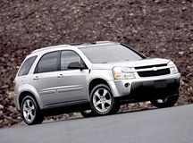
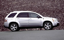
To help understand
the unique service features of the new 2005 Chevrolet Equinox (fig.
1), refer to bulletin 04-00-89-006. It provides the complete
pre-delivery procedure and important service tips. Here are some highlights.
QUALITY PRE-DELIVERY INSPECTION
TIP: A quality
pre-delivery inspection is your dealership’s first contact with
a new vehicle. And, it’s your first opportunity to influence the
customer’s perception of your dealership and increase their satisfaction
with the new vehicle.
Be sure two keys and fobs are included with
the vehicle.
Ensure that the following loose items are
fitted to the vehicle:
- Floor mats
- Antenna
- Front license plate bracket
As soon as the vehicle reaches the dealership, remove the protective
film from:
- Front and rear fascias
- Mirrors
- Rocker panels
The vehicle is shipped with extra air in the tires. Adjust tire
pressure to 30 psi (207 kPa). The tire pressure label
is located at the bottom of the driver side B-pillar.
Where required, install the front license plate hardware.
The front fascia has two locating dimples for this purpose.
UNIQUE VEHICLE CHARACTERISTICS
There is airflow from the outer HVAC vents
in all modes, to improve side window defogging (fig.
2).
The Equinox is available with both FWD and AWD drivetrains. Some Equinox
models have a traction control button next
to the Equinox name in the center of the IP and some don’t.
Button -- FWD vehicles with ABS
No button -- FWD vehicles without ABS, AWD vehicles
TIP: AWD vehicles
can easily be identified by the emblem on the rear hatch.
The cigarette lighter and accessory power outlets
operate only with the ignition in ACC or ON position.
Only the radio is functional in the RAP (Retained
Accessory Power) mode. The power windows will not function
in RAP. This is normal.
The control for the outside rearview mirrors
is located to the left of the steering wheel on the IP.
The roof rack is located by the assembly plant
in the optimal location for minimizing wind noise.
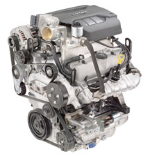
ENGINE
The 3.4L (RPO LNJ -- VIN F) engine is similar to other 3.4L engines,
but is not interchangeable (fig. 3).
TIP: An engine
exchange program is in effect for the first six months.
The crankshaft sensor is located on the right
side of the block, next to the bulkhead. The reluctor wheel
is located on the crankshaft.
It is important to follow the bulletin procedure to ensure air is removed
from the cooling system, to avoid coolant
noise concerns. If coolant must be drained, at least 5 liters (5.28
quarts) must be removed, and this is the minimum amount to be added
when the system is refilled.
TIP: It may be
necessary to raise the RH front corner of the vehicle 3 inches (76 mm)
to force trapped air toward the air bleed.
TRANSAXLE
The Aisin Warner AF33-5 transaxle has 5 speeds, is electronically controlled,
and features an adapt function.
Shift pressures are automatically adjusted for temperature, altitude,
and transaxle component wear, using a process called adaptive self-learning.
The adaptive procedure is based on counting the number of upshifts,
not driving time or distance.
TIP: It may be
necessary to drive far enough to consume a full tank of gas to allow
the transaxle to adapt to a particular driver’s habits.
TIP: If the transaxle
is replaced, the adaptive function must be reset to default settings,
using the Tech 2. Follow this path:
Enter F0: Diagnostics
Select 2005 Model Year
Select LD Truck
Select Chevrolet Truck
Select L Product Line
Confirm Engine (3.4L LNJ)
Confirm Trans 5 Spd - Auto
F0: Powertrain
F2: Special Functions
F1: Transmission Output Controls
F5: Reset Transmission Adapts
The Aisin AF33-5 provides uphill and downhill
modes. When driving uphill, the driver may notice that it is not necessary
to increase throttle position. This is because the transaxle up- or
downshifts as necessary to maintain speed. This is normal operation.
When driving downhill, the transaxle will
assist in maintaining speed by applying clutches to achieve automatic
grade braking. This feels similar to brake application, and is normal
operation.
The transaxle is equipped with an ATF oil life monitor,
which illuminates the SES light when oil life reaches 10%. A DTC P1868
indicates the need to change fluid.
TIP: Only T-IV
fluid may be used (US 88900925, Canada 22689186). DO NOT use Dexron
III.
Reset the oil life monitor accordingly.
Refer to the bulletin for additional mechanical service procedures,
including checking and adding fluid.
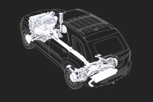
ALL-WHEEL DRIVE (AWD) SYSTEM
The all-wheel drive system uses the familiar Versatrak components to
provide power to the rear wheels if slip is detected at the front wheels
(fig. 4).
Refer to the bulletin and SI for service procedures.
ELECTRICAL ARCHITECTURE
The Equinox relies on both Class II and GMLAN for communication. The
following modules rely on GMLAN:
- Transmission control module
- Brake module
- ECM
- OnStar module (also uses Class II)
- BCM (gateway between Class II and GMLAN)
TIP: It is necessary
to use a CANdi module to communicate with the Tech 2. This has been
covered in numerous TechLink articles: Mar. 2003, Aug. 2003, Dec. 2003,
Jan. 2004.
CHASSIS/SUSPENSION
The suspension is independent at both front and rear, with MacPherson
struts in the front and four-link with coil springs in the rear (fig.
5).
Camber and toe can be adjusted in front and rear, but caster cannot
be adjusted at either end.
TIP: Alignment
cams are not installed in the rear suspension during production. Service
cams are available.
ELECTRONIC POWER STEERING (EPS)
EPS eliminates hydraulic lines and the belt-driven pump, reduces engine
load (potential mileage improvement), and reduces operating noise.There
are fewer components to service and diagnostics are more accurate.
Major components of the EPS system are the Power Steering Control Module
(PSCM), a torque sensor and the Electronic Power Steering motor. The
PSCM, torque sensor and motor are serviced ONLY as an assembly.
TIP: Whenever
a PSCM is replaced, it must be set up with the proper tuning profile.
AUDIO SYSTEM
The MP3 player accepts MP3 files that are recorded on an up-to-700 MB
CD-R. The player is able to read and play a maximum of 50 folders, 50
playlists, 10 sessions, and 255 files.
TIP: These capacities
may be reduced if long names are used, or a large number of elements
are stored.
TRAINING COURSES
Two training courses are available for learning more about the Equinox:
- 10280.14D New Model Features (EPS and AWD)
- 17341.10V Aision AF33-5 Automatic Transaxle
TIP: In Canada,
watch for the 2005 Equinox Features Know-How release..
-
Thanks to Ange Girolamo and Ann Briedis |
|
figure
1 |
|
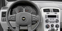
figure 2 |
 figure
3
figure
3 |
figure
4
|
|
figure
5
|
|
| |
| |
| return
to Table of Contents |
|
|
| Business
Grade PC Specifications |
A TechLink article in Dec. 2003 mentioned that GM Service Operations
is ending support for Windows 98, Millennium and NT operating systems,
effective January 15, 2004. For this reason, many dealers are upgrading
and adding PC equipment.
The right PC is as important to a technician’s efficiency and
productivity as having the right tools in the toolbox. Because it’s
important that dealers purchase the correct type of PC, here are some
reminders.
TIP: Refer to
Hardware Specs on http://service.gm.com for additional information on
minimum and recommended PCs.
Unlike a consumer grade PC, a business grade or commercial
PC is specifically configured for use in a business network
environment. PCs in this class have components designed and supported
for use in a network environment. Additionally, they have greater life
cycle stability due to designed-in serviceability. Techline applications
will not function properly on typical non-business grade hardware designed
for home use.
Although consumer grade PCs may have a more attractive price, their
limitations far exceed their initial cost savings, making them not much
of a bargain in the end.
Characteristics of Business Grade PCs
- Extended product availability cycles
- Built using same components for generally 3 to 6 months
- Ease of serviceability of internal components
- Preloaded with business software
- Network manageability, utilizing industry standards to manage setup
and maintenance
Characteristics of Consumer Grade PCs
- Designed with multi-media hardware features used for gaming, video,
music
- Preloaded with multi-media software designed for entertainment
- Multi-media software can cause conflicts with Techline application
software
- Not assembled with same internal components through product build
lifecycle
- Validation for Techline applications impossible, due to inconsistent
internal component build
- Designed for home networking configurations
- Preloaded with internet-ready configurations designed for the home
user
TCSC PC Support
Validated PC platforms (i.e., HP d530, IBM NetVista, Dell Optiplex,
and Gateway E Series) receive full hardware and software support.
Any PC that meets the minimum hardware spec (P III 600 MHz, 128 MB RAM,
WIN 2000 or XP Pro, serial port, IE 6.0, HD 20 GB) but is a non-validated
hardware platform will receive support for the Techline applications
only. Support ends if the problem is determined to be hardware related.
TIP: AMD and
Intel Celeron processors are non-supported hardware. Service Programming
Systems (SPS) does not function reliably with typical Celeron and AMD
processors. When a Techline PC is interfacing with the Tech 2, the bilateral
communication rate and data transfer speed is critical for SPS to function
successfully. These processors have proven unreliable in this process.
Dealers with PCs that do not meet minimum spec requirements are asked
to replace the PC or upgrade the operating system.
Before making a PC purchase, please contact your Regional Techline Field
Consultant (TC) to ensure your PC meets or exceeds the recommended specifications.
TC contact information can be found at http://service.gm.com
under the Techline tab, or call the Techline Customer Support Center
at 1.800.828.6860 for additional assistance.
-
Thanks to Mike Waszczenko and Shawn Sullivan |
|
|
|
|
XLR Electrical Switches |
Several
electrical switches have been replaced unnecessarily on 2004 Cadillac
XLRs.
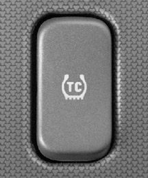
Traction Control Switch
The traction control switch on the center console is a typical rocker
switch (fig. 6), intended to rock in only
one direction. To turn traction control off, press the switch. To turn
traction control on again, press the switch again.
TIP: Do not replace
the switch if the customer is concerned that it rocks in only one direction.
This is as designed.
Be sure you also understand the following traction control operating
conditions, to avoid unnecessary service.
TIP: When traction
control is turned OFF, a traction control warning light is illuminated.
The light is NOT illuminated when traction control is enabled.
TIP: Traction
control is re-enabled automatically each time the ignition is turned
on, even if it was manually turned off during the last ignition cycle.
Power Window Switch and Module
The following is normal operation, and is not reason to replace the
switch or module (fig. 7).
If the window module sees voltage below 8v, it will set a DTC B1327
and the window will not operate.
TIP: The DTC
will not clear unless voltage is increased above 9v.
Once the battery is charged, or the engine is started, the DTC will
clear and the window will operate.
TIP: When voltage
raises above 9v, the DTC will move from current code to history code.
If you replace the module (which is not at fault) and then the voltage
is raised above 9v, it will look like replacing the module fixed the
“problem,” when actually there was no problem, other than
low voltage.
When the warranty claim is reviewed, if no trouble is found with the
replaced part, it will be charged back to the dealer..
- Thanks to Brad Thacher |
figure
6 |
| 
figure
7
|
return to Table of Contents |
|
| Modular
Fuel Pump Terminals |
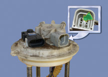
This
diagnostic tip applies to modular fuel pumps on C/K pickup, S-truck,
Cavalier, Sunfire and Malibu.
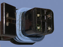
Before condemning a fuel pump, check the teminals in the connector on
the pump module (fig. 8) and in the wiring
harness connector (fig. 9). If a harness
terminal is spread apart, it will cause excessive resistance, which
leads to overheating of the terminal.
If you discover this condition, replace the harness connector and terminals
with the appropriate service pigtail, available from GMSPO.
-
Thanks to Dennis Kissack |
|
figure
8 |
figure
9 |
| return
to Table of Contents |
|
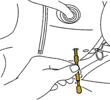
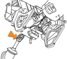
| Using
Anti-Rotation Pin |
Most GM vehicles are equipped with a steering column that can be locked
using special tool J-42640 (anti-rotation pin). The pin fits into the
bottom of the steering column lower shroud (fig.
10).
The J-42640 must be installed whenever:
- the steering column is removed from the vehicle
- the intermediate shafts are disconnected
- wheel position sensor, steering wheel or SIR coil is removed.
Failure to lock the steering column could result in damage to the SIR
coil.
IMPORTANT: Do
not tilt the steering column with the J-42640 pin installed. Tilting
the steering column with J 42640 installed may cause damage to the steering
column or instrument panel lower trim panel.
IMPORTANT: You
MUST perform all of these steps to ensure that the intermediate shaft
does not become misaligned or the SIR coil become uncentered. Failure
to do so may cause damage to the SIR coil.
1. Position the wheels of the vehicle straight ahead.
2. Turn the ignition switch to the Lock position.
3. Install J 42640 (anti-rotation pin) to the steering column, if it
has an access hole in the lower shroud, to lock the steering column
shaft.
4. Make an alignment mark on the intermediate shaft to the steering
column, gear, or connecting shaft (upper to lower), to aid in re-installation.
TIP: Some steering
columns do not offer any external locking features. On these vehicles,
be careful to prevent the steering column shaft from rotating during
service of the steering column, intermediate shafts, steering wheel,
wheel position sensor, or SIR coil.
If it is determined that the steering column shaft has rotated, it will
be necessary to re-center the SIR coil. Refer to the SIR coil centering
procedure in SI.
-
Thanks to Steve Hathaway |
figure
10 |
| return
to Table of Contents |
|
| Ignition
Key Replacement |
This
information applies to 1997-2003 Buick Park Avenue.
A change was made to the ignition key for the model year 2004 Buick
Park Avenue, due to a change in supplier tooling. The head of the new
key P/N 89023231 is wider than the tabs of the ignition switch of 1997-2003
Park Avenues.
If 89023231 were used as a service replacement key on past model year
Park Avenues, the ignition cylinder would have to be replaced as well.
To avoid this, key P/N 88891799 is being released by SPO. This key will
fit the existing ignition cylinders on past model Park Avenues, eliminating
the need to replace the ignition cylinder.
-
Thanks to Kobie Glenn |
|
|
| return
to Table of Contents |
|
| Mis-Coded
Warranty Claims |
According
to a recent survey, over 75% of the warranty claims for engine oil dipsticks
are mis-coded. Here are the correct numbers.
J0920 |
Dipstick
(oil level indicator) |
J0930 |
Dipstick
Tube |
N4580 |
Oil
Level Switch (sensor) |
The dipstick (or
oil level indicator) is the graduated metal rod or wand that is used
to indicate the depth of the oil in the engine’s oil pan. The
dipstick is inserted into the dipstick tube in the engine block. And
the oil level switch (sensor) is an electrical sensor installed into
the engine oil pan that is used to detect when the oil has dropped below
a safe level.
-
Thanks to Tom Spix |
|
return
to Table of Contents |
|
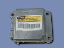
| Air
Bag Module Checkout |
Extra
attention is needed if a vehicle comes in for service with the air bag
telltale illuminated. After reading diagnostic trouble codes and finding
that air bag loop faults and/or sensor faults are current, take the
time necessary to troubleshoot the wiring fully. Replacing the SDM (fig.
11) will not correct the fault in many situations. A detailed
check of continuity for the faulted lines is necessary.
TIP: Check all
wiring connections before removing and replacing the SDM.
- Thanks to Tom Nguyen |
figure
11 |
| return
to Table of Contents |
|
| Inadvertent
Switch Activation |
This information applies to 2003-04 Topkick and Kodiak C4500-C8500 series.
Bulletin 03-07-30-047 explains that inadvertent operation of several
instrument panel switches can cause unusual transmission performance.
If the Power Takeoff (PTO) switch is accidentally turned on, it will
limit engine operation to 2000 rpm, which results in long, delayed upshifts.
Also, changes in transmission operation or feel can result if the Overdrive
Defeat switch is left in the on position.
Before attempting shifting related repairs, check the position of these
two switches, and be sure the customer understands their operation.
TIP: A center
passenger’s knee can contact the PTO switch, resulting in it being
switched on unexpectedly.
-
Thanks to Dan Oden |
|
|
|
return
to Table of Contents |
|
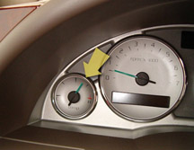
| Temperature
Gauge Readings |
Starting in January 2004, the Buick Rendezvous is available with a new
3.6L LY7 engine. Customers may notice the engine temperature gauge reading
slightly past the mid point (fig 12) under
heavy loads, in high ambient temperatures, in stop and go traffic, and
mountain driving. This condition is a normal operating characteristic
of this powertrain.
A customer may also notice more movement in the engine temperature gauge
than is traditionally seen with other powertrains. Customers should
be reassured the gauge reading as described is normal for this vehicle.
TIP: A gauge
reading in the red zone indicates a true overheat condition.
In the LY7 engine, the coolant temperature sensor is located in an area
subjected to higher engine temperatures and more temperature fluctuations
during normal operation of the cooling system.
-
Thanks to Russ Gilbert |
figure
12
|
|
return
to Table of Contents |
|
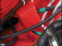
| SSR
Remote Battery Terminal |
The
battery on the SSR is located beneath the rear of the vehicle.
Reviews of returned SSR electrical components (BCMs, RDMs, cooling fan
components and circuitry) indicate components are being damaged due
to improper jump starting and battery charging procedures.
Follow instructions in SI or the owner's manual. There is a remote battery
positive terminal located on the right front inner fender and a nearby
engine ground (fig. 13).
- Thanks to Dan Oden |
figure
13 |
|
return
to Table of Contents |
|
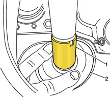
| Steering
Column Noise |
Owners
of some 2002-03 Chevrolet TrailBlazers, GMC Envoys and Oldsmobile Bravadas
may comment on a squeak noise coming from the steering column while
turning the steering wheel. Some customers may also comment on a rubbing
or scrubbing type noise or feel in the steering wheel during low speed
turns or parking maneuvers. The condition may be more pronounced in
cold temperatures.
Bulletin 02-02-35-006A provides details for lubricating the serration
(slip) joint of the upper intermediate shaft to address the squeak noise
(fig. 14).
The rubbing or scrubbing type noise may be addressed by removing material
from the upper intermediate shaft bushing to alleviate an interference
fit between the upper intermediate shaft boot seal and the intermediate
shaft bushing (fig. 15).
TIP: Do not replace
the upper or lower shaft to repair these conditions.
- Thanks to Don Sherman
| Part
Number |
Description |
12346293
(Canadian 992723) |
Lubriplate
Lubricant Spray Grease |
|
figure
14 |
|
figure
15
|
| return
to Table of Contents |
|
| Pictorial
Service Information |
GMSPO
(GM Service and Parts Operations) is working to develop a new way to show
mechanical service information in the service manual. At present, a step-by-step
approach provides a small illustration and some words to tell you what
steps to perform to remove and replace the part.
With this format, it can be hard to find some things, and the extensive
use of links can be confusing. Printing a procedure can take quite a few
pages, as well.
The new format is called “pictorial.” As the name implies,
it’s based on a much larger illustration that shows the parts according
to disassembly sequence. A new, easy-to-follow numbered table corresponds
to the parts shown in the illustration.
The table uses the same part name that the GM Parts catalog uses, along
with special tool references, torque values, cautions and notices, and
what we call a “tip.”
The Service Tips are shorthand for the procedure steps that need to be
performed. If the illustration needs clarification, or if there is something
we’d like to tell you about the step, we’ll include it as
a tip.
What we won’t do is to tell you the obvious. For example, if a part
is attached with four screws, and this is made obvious in the illustration,
then we’ll just give you the part name. It’s not necessary
to tell you to remove the screws.
The illustration itself will be as large as three quarters of a printed
page. The table will follow under the illustration. In most cases, if
you print the material on your printer, it will be no more than two to
four pages. Because torque values are included within the table, you won’t
need to print the torque specification page as a separate item.
The new illustrations are designed to provide you with enough information
so you know where things are on the vehicle – what we call “vehicle
context.” We will also show parts that help in understanding the
overall assembly, even though the detail for servicing them may be in
another section of the manual.
The Table of Contents will remain as it is today. The older format will
work just fine next to the new format, so there was no need to change
how you navigate around the system.
Another new feature -- “assembly illustrations” -- will be
included when there is sufficient complexity to warrant their use. For
example, the front brake system is fairly easy to show in one or two illustrations,
while the instrument panel is hard to show that way. Wherever possible,
the assembly illustration will be the same one used by the parts catalog.
So if you need a part, you can identify it on the service manual illustration
to show to the parts department.
We can also sequence you through a complex repair. You could start out
by looking at the assembly illustration. Depending on your level of experience
with a particular model, this might be all you need to complete the job.
If you need more information, a link will take you to the next step. If
you know exactly where you want to go, you can still use keywords, or
navigate with the mouse. Either way, you will be presented with a listing
of selections just as you are today. If you want to see the procedure
just for the radio, for instance, it will still be there in the list.
Click on it and you will be directed to it.
We’re pretty excited about this and think it will make your job
a little easier. You’ll print fewer pages. You’ll have the
correct part name, the torque value and appropriate service tips, and
in many cases, the same illustration used by the parts department.
You’ll start to see this new format roll into Service Information
as vehicle content changes over time. To change everything at one time
is more than we can do. Next month, we’ll talk in more detail about
these new features, and will show you what the new format will look like.
Then we’ll talk about what models and sections you’ll start
to see converted first.
As always, your feedback is really important to us. As you start to see
the new format and want to comment, we’ll be here and ready to listen.
- Thanks to Bob Scherer |
| |
| return
to Table of Contents |
|
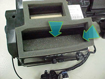
| HVAC Cables |
Bulletin
03-01-38-005A covers various HVAC concerns on 2003-04 Chevrolet Cavalier
and Pontiac Sunfire related to mode and temperature control cables.
Be sure to refer to the bulletin for details. Here are some highlights.
Because symptoms show up as a control knob that is difficult to move,
blame is often placed wrongly on the control head. The control head
has not been identified as a cause of effort concerns, although the
head may become damaged by forcing a knob to overcome an operating condition
elsewhere.
TIP: Be sure the cable mounting tabs on the control
head are intact.
Cable Conditions
The bulletin points out that a cable may bind, or may become kinked,
due to:
- Improper cable routing -- Be sure routing does not
cause cable housing or cam interference when the control head knob is
operated.
- Improper cable clip positioning -- May have been
improperly installed at assembly, or may have pulled off by forcing
the control head.
- Cable interference with wiring -- Tie back wiring
as necessary.
- Stuck or binding valve -- The defrost valve arm may
drop off the edge of the surface and become stuck. The bulletin details
how to grind the area. Foam or adhesive may interfere with operaton
of defrost and mode valves (fig. 16). The
bulletin explains how to trim the material to allow free operation.
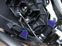
Repair Tips
Here are some general tips.
- For diffiucult mode valve operation, where the valve is not stuck,
check the mode cable housing for interference with the cam. The cable
can interfere with the cam during rotation (fig.
17), causing a condition of low effort, high effort then low
effort again.
- If a cable is kinked or stretched, replace it.
- Cables don’t have to be replaced in pairs.
- If routing or clip position was incorrect, be sure to fully function
test after making repairs.
- If a cable and clips are not damaged, the cable may be re-used.
TIP: Part number
89018237 (seal kit) is NOT required when replacing a cable. The parts
book will be updated on April 1.
- Thanks to Steve Oakley
| Part
Number |
Description |
| 89018243 |
Cable,
Mode Control |
| 89018243 |
Cable,
Temp Control |
|
figure
16 |
figure
17 |
| return
to Table of Contents |
|
| The
Value of Closing TAC Cases |
Why
spend the time to close a TAC case?
Case closings are one of the most important parts of using TAC. Case closing
information is specific repair knowledge that TAC learns from you and
other technicians. Your case closing helps provide how-to-fix information
to another technician with a similar condition.
The importance of case closing is also demonstrated by the use of your
closing information in PI (preliminary information) and/or service bulletin
development. These PIs and bulletins are then available to all dealers,
which in turn helps all of us provide outstanding repair service to our
customers.
Imagine a technician at a dealership in Oregon who finds the root cause
of a noise that has taken three days to diagnose. A detailed closing is
sent in to TAC, and a TAC consultant uses it to help a technician in Florida
repair another vehicle the next day, with all that time saved.
How to Close a Case
TIP: Specific case
closing details and guidelines are located in the Dealer P & P Manual
- Section 5.3.
Cases should be closed in a timely manner; ideally, on the same day the
vehicle is repaired or the repair order is closed. With timely closings,
you will be able to remember all the specific details of the repair.
US Dealers
The TAIF (Technical Assistance Information Form) asks for the following
basic information to close a TAC case.
- TAC Case Number
- Labor Op Number
- Detailed information on what actually fixed the vehicle.
There are two ways to close a TAC case:
1. Call the VME phone-in system at 1.888.446.8227, prompt 1
2. Use the fax-in system by sending a fax to 1.800.541.1761.
Canadian Dealers
Active TAC cases for your dealer code can be found on the GM InfoNET.
When the repair order is closed, locate the case on the GM InfoNET website
and submit explicit details of your resolution, a labor operation, applicable
part numbers and supporting attachments (such as pictures and Tech 2 snapshots).
So, why spend the time to close a TAC case? The answer is pretty simple.
Your closing helps other technicians, and other technicians’ case
closings help you. The more detailed and accurate closings we get, the
more we help each other. Thanks to all of you that send in detailed and
accurate case closings.
- Thanks to Dave Slaughter and Bill Szelag |
| |
| return
to Table of Contents |
|
| Intentional
Lack of Sealant |
Some
owners of regular and extended cab 2004 Colorado and Canyon pickup trucks
are commenting on the lack of seam sealer at the headboard of the pickup
box. These vehicles are built as designed and have successfully undergone
extensive corrosion testing. No repairs are necessary.
Engineering is making changes to provide a more finished appearance for
the unfinished edges. There is no plan to install sealer at this time.
- Thanks to Bill Detrick |
| |
| return
to Table of Contents |
|
| DVD
Player Concern |
On
the 2004 Chevrolet Malibu Maxx, do not swap the DVD player from a known-good
vehicle for diagnostic test purposes. The DVD player will operate ONLY
in the vehicle in which it was originally installed. It learns the vehicle's
VIN from the BCM on the first ignition cycle after it is installed.
A new VIN cannot be learned.
TIP: It is OK
to swap the LCD screen from a known-good vehicle for diagnostic test
purposes only.
-
Thanks to Bruce Moss |
| return
to Table of Contents |
|
| Delayed
Door Lock Feature |
The
2004 Cadillac SRX has a delayed door lock feature. If the customer does
not understand its operation, the normal function may appear as a problem.
TIP: Refer to
Owner's Manual page 2-9 (SI document 1206797) for an explanation of
how the Delayed Locking feature operates, and page 3-89 (SI document
894492) for the procedure to turn the feature ON and OFF using the DIC.
If the feature is turned ON and the customer presses the door lock switch
to the Lock position, a chime is heard, and the doors will lock about
5 seconds after the last door is closed. Pressing the Lock button a
second time or holding the switch down for 3-5 seconds will override
the Delayed Locking feature and will lock the doors immediately.
-
Thanks to Roger Jantz |
| return
to Table of Contents |
|
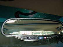
| Headliner
with Sunroof |
Owners
of some 2003-04 Buick Regals with sliding sunroof may comment about
a sagging headliner ahead of the rear window. This may be most noticeable
in the rearview mirror (fig.18).
The sunroof drive motor was relocated to the rear of the sunroof and
the headliner is reshaped to provide clearance.
TIP: This is
a normal condition and no repair should be performed. See bulletin 03-08-110-007
for details.
-
Thanks to Wayne Zigler |
figure
18 |
| return
to Table of Contents |
|
| SSR
Roof Operation when Cold |
Be
sure owners of the 2004 SSR understand this feature of top operation.
If the convertible top has not completed its movement from one position
to another within the programmed time limit, a Roof Cycle Timeout message
will be displayed on the DIC. When this message appears, the convertible
top will stop moving. Release the convertible top switch and make sure
there is nothing blocking the path of the top. If the path is clear, turn
the ignition off and on again. Then press the convertible top switch again.
When operating the top in low temperatures -- below 32°F (0°C)
-- the time needed to cycle the top will increase. This may cause the
top movement to stop and the Roof Cycle Timeout message to appear on the
DIC. If this occurs, release the convertible top switch and depress it
again to continue the cycle. Make sure nothing is blocking the path of
the top before depressing the switch again. It may be necessary to do
this several times to complete the cycle, depending on the outside temperature.
TIP: If the convertible
top switch is operated continuously while the ignition is in ACCESSORY,
the battery will drain and it may be difficult to start the vehicle. Do
not use the convertible top switch for extended periods of time when the
ignition is in ACCESSORY.
-
Thanks to Dan Oden |
| |
|
return
to Table of Contents |
|
 Car Issues – Fix It Right The First Time (new issues in bold)
 |
Model
Year(s) |
Vehicle
Line(s) --
Condition |
Do
This |
Don’t
Do This |
Reference
Information / Bulletin |
1999-2004 |
All
Cars and Trucks – Brake Warranty, Service and Procedures |
1.
Refinish brake rotor
2. Measure for LRO |
1.
Don’t replace the brake rotors.
2. Don’t fail to measure for LRO |
00-05-22-002C |
2003-2004 |
CTS
– Variable Effort Steering (VES) “Service Steering
Message,” DTC C1241 or C0450 |
Replace
only VES solenoid |
Don’t
replace the entire steering gear. |
03-02-36-001 |
2001-2003 |
All
cars with 4T40/45E, 4T65E and 4T80E – Code P0742 |
Replace
TCC PWM Solenoid |
Don’t
replace transmission, torque converter or valve body assembly. |
02-07-30-039C |
2000-04 |
Cavalier/Sunfire
– Air Conditioning Compressor Noisy |
Inspect
for ground outs that can cause A/C compressor noise |
Don’t
replace A/C compressor for noise without inspecting for ground
outs. |
03-01-38-012 |
2004 |
Cavalier/Sunfire/Alero/Grand
Am – Inoperative Sunroof Module |
Retime
module or replace only motor |
Don’t
replace entire sunroof module assembly. |
03-08-67-009 |
2001-04 |
Century/Regal
– Intermittent SES, ABS or TCS Lamp Illuminated, Engine
No Crank/No Start, Various I/P Cluster Intermittents, DTCs Set,
Shifter Locked in Park |
Check
UBEC harness connectors for damage and replace damaged terminals |
Don’t
replace UBEC, ignition switch, SDM, BCM, shifter assembly or intermittent
clusters. |
03-08-45-004 |
1998-2004 |
Seville
– Heated Seat Inoperative |
Replace
only needed heating element. |
Don’t
replace entire seat cover |
01-08-50-002C |
2000-2004 |
All
Cars with 4T40/4T45E and 4T65E – Light On, Various Transmission
Codes Stored |
Check
trans 20-way connector for secure connection (disconnect, reconnect). |
Don’t
replace transmission, TCC PWM, VSS, PCS or valve body. |
02-07-30-022B |
2002-03 |
Impala
– Snap/Clunk when Window is Rolled to Full Up Position |
Replace
glass run channel with revised part. |
Don’t
replace front window regulator, door glass or align door glass |
03-08-64-034 |
1999-2004 |
1999-2003
Park Avenue, 2000-2004 LeSabre – Ash Tray Will Not Remain
Closed |
Use
I/P ash tray latch as service repair. |
Don’t replace complete ash tray assembly. |
03-08-49-005 |
|
| return
to Table of Contents |
|
|
 Truck Issues – Fix It Right The First Time (new issues in bold)
|
Model
Year(s) |
Vehicle
Line(s) --
Condition |
Do
This |
Don’t
Do This |
Reference
Information / Bulletin |
2002-04 |
Chevrolet Avalanche and Cadillac Escalade EXT – Cargo Covers
and Cladding Faded or Stained |
Thoroughly
clean, dry and treat components with Armor-dillo. To order (888)393-4722
or www.armor-dillo.net. |
Don’t
replace cargo covers for this condition. |
04-08-111-001 |
2002-04 |
Fullsize and Midsize Pickups and Utilities – Transfer Case
CNND Labor Operation |
Use
Labor Operation K9993 whenever a transfer case issue on a 4WD
or AWD vehicle cannot be duplicated or resolved after diagnostic
efforts. |
Don’t
use K9992, which is for manual concerns or K9995, which is for
automatic concerns. |
Service
VME
VSSM20030117 |
1999-2003 |
Fullsize Pickups – Rear Leaf Spring Slap Noise |
Replace
inserts and rubber washers. |
Don’t
replace the leaf spring. |
03-03-09-002 |
1993-2004 |
All
Passenger Cars and Trucks – Air Conditioner Compressor Diagnosis |
Follow
SI and bulletin for diagnostic information before compressor replacement. |
Don’t
replace air conditioning compressor |
Service
VME, 10/31/03
01-01-38-013A |
2002-04 |
All TrailBlazers, All Envoys, Bravada, Rainier with HomeLink Universal
Transmitter – Programming Diagnosis |
Use
J 41540 – GM Integrated HomeLink Tester. Follow SI and refer
customers to Owner’s Manual. |
Don’t
replace HomeLink Transceiver without validating internal fault
recognized by J 41540 |
01-08-97-001B |
2002-2003 |
All
TrailBlazers, Envoy, Envoy XL, Bravada – Squeak/Rub/Scrub
Type Noise in Steering Column |
Lubricate
and remove material, per bulletin. |
Don’t
replace upper or lower intermediate shaft. |
02-02-35-006A |
2003-04 |
Fullsize
Pickups and Utilities – Servicing Wide Load Mirrors (RPO
DPF) |
Replace
individual parts as needed. |
Don’t
replace the complete mirror assembly. |
03-08-64-028 |
2003 |
Fullsize
Pickups and Utilities – Transfer Case Service Light/New
Venture Gear Transfer Case |
Verify
that the encoder motor is the primary cause. Replace encoder motor
sensor and reprogram TCCM.
Labor Operation: K9980 |
Don’t
replace the module, encoder motor or transfer case for DTCs C0327,
P0836, P0500 |
03-04-21-001D |
2003 |
Fullsize
Pickups – 6.6L Diesel Engine ECM |
Follow
SI and bulletins for proper diagnostics for P0181. Refer to Owner’s
Manual (block heater and front cover) |
Don’t
replace ECM (DTCs P0540 and P0181) unless diagnostics confirm
need to replace |
02-06-04-048
03-06-04-021
02-06-04-058 |
2002-2004 |
All
TrailBlazers, All Envoys, Bravada, Rainier – Mirror Erratic
Return |
Replace
mirror actuator and reprogram module |
Don’t
replace outside mirror assembly |
02-08-64-008
02-08-64-021
03-08-64-033 |
|
| return
to Table of Contents |
|
|
| Know-How
Broadcasts for May |
| |
 |
| Know-How
Broadcasts for May |
| 10280.05D
Emerging Issues |
May
13, 2004 |
9:00
AM, 12:30 PM,
3:00 PM
Eastern Time |
| 10280.17D
New Model Features -- 2005 Cadillac |
May
27, 2004 |
9:00
AM, 12:30 PM,
3:00 PM
Eastern Time |
| -
Thanks to Tracy Timmerman |
|
|
| return
to Table of Contents |
|
