|
||||||||||||||||||||||||||||||||||||||||
| |
||||||||||||||||||||||||||||||||||||||||
|
|
||||||||||||||||||||||||||||||||||||||||
|
Testing Fuel Injectors -- Misfires |
With the inception
of OBD 2 vehicles, being able to correctly diagnose misfires has become
more important to the service technician. The causes of misfire codes
(P0300 or P0301-08) can range from low compression to poor fuel quality.
Of course, basic tests must be made to determine the root cause of the
misfire. If injectors are suspect, you must perform diagnostics to evaluate
injector performance (fig. 1).
|
|||||||||||||||||||||||||||||||||||||||
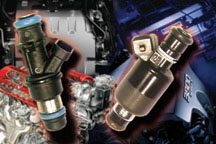
figure 1 |
||||||||||||||||||||||||||||||||||||||||
figure 2 |
||||||||||||||||||||||||||||||||||||||||
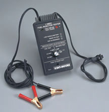 figure 3 |
||||||||||||||||||||||||||||||||||||||||
 figure 4 |
||||||||||||||||||||||||||||||||||||||||
| return to Table of Contents | ||||||||||||||||||||||||||||||||||||||||
| TechLink Website Update |
By
now, we hope you’ve discovered the renovated TechLink website
at http://service.gm.com. This version went online in October. |
|||||||||||||||||||||||||||||||||||||||
| return to Table of Contents | ||||||||||||||||||||||||||||||||||||||||
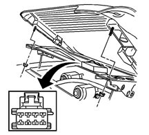
| Front
End Alignment |
This
information pertains to C/K trucks, G-Vans and Hummer H2. |
|||||||||||||||||||||||||||||||||||||||
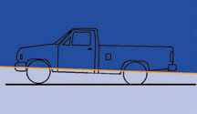 figure 6 |
||||||||||||||||||||||||||||||||||||||||
| return to Table of Contents | ||||||||||||||||||||||||||||||||||||||||
| |
||||||||||||||||||||||||||||||||||||||||
| Seat Belt Post Cover |
This
revised procedure applies to 1998-2003 Cadillac Seville. To remove the
front seat belt post cover without breaking it, begin by removing the
two trim cover screws. - Thanks to Martin Stark |
|||||||||||||||||||||||||||||||||||||||
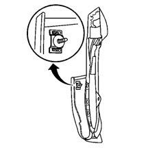 figure 7 |
||||||||||||||||||||||||||||||||||||||||
| return to Table of Contents | ||||||||||||||||||||||||||||||||||||||||
|
|
||||||||||||||||||||||||||||||||||||||||
| Know-How Broadcasts for January |
|
|||||||||||||||||||||||||||||||||||||||
| return to Table of Contents | ||||||||||||||||||||||||||||||||||||||||
|
|
||||||||||||||||||||||||||||||||||||||||
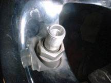
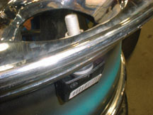
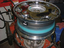
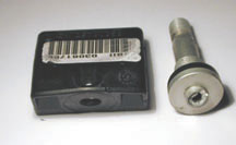
| Tire Pressure Monitoring System Update |
A
tire pressure monitor (TPM) system is used on Cadillac DeVille and Seville
and Chevrolet Corvette. This system was discussed in the November 2000 TechLink; this is a brief review, because there is some new service information. Components There is a separate sensor/transmitter in each wheel. The TPM system shares the receiver with the keyless entry system. Data from the receiver is displayed on the instrument panel, using the driver information center (DIC). Sensors The sensor, with built-in valve stem, is inserted from the inside of the wheel, through a hole in the rim. It is retained by a nut (4 N.m, 35 lb. in.) and is sealed by a grommet (fig. 8). The sensor is powered by a lithium battery with a design life of 10 years. Each sensor is coded differently. This permits the receiver to determine exactly which tire is over- or under-inflated. Operation The sensors operate only above 20 mph (32 kph) and transmit once per hour when parked, to preserve battery power. If the pressure in a tire rises or falls outside the calibration limits, the condition is displayed by the DIC. The low limit is 24 psi (168 kPa) and the upper limit is 39 psi (272 kPa). Service The sensors are lightweight, only about an ounce (28 g), and this small weight is easily accounted for during normal tire balancing (fig. 9). The sensors are mounted within the well of the rim. It’s important to be careful when using a tire mounting machine (fig. 10). The sensor could be damaged in two ways: either by direct contact with the machinery or by the bead of the tire as it is forced over the rim (fig. 11). The valve stem cap is made of aluminum and the valve core is nickel-plated to resist corrosion. The end of the stem serves as the sensor’s antenna. TIP: Do not replace either the cap or the valve with standard parts. This will interfere with the sensor’s ability to transmit. TIP: The TPM sensor is more precise than consumer-grade tire pressure gauges. It may be necessary to explain this if the customer routinely mis-inflates tires using a gas station gauge. Receiver Programming The receiver is programmed at the factory to recognize which sensor is at each wheel location. If tires are rotated or a sensor is replaced, the receiver must be reprogrammed, following SI procedures. If the receiver is not reprogrammed, the system will continue to report the correct pressures, but will assign them to the wrong locations on the vehicle. TIP: There are two reprogramming methods. You must use the J-41760 magnet (fig. 12) when a new sensor is installed. During tire rotation, you can use either the magnet or your Tech 2. Magnet Method -- You will have only one minute between horn chirps, and five minutes overall, to complete the procedure once you start. With ignition on, engine not running, press both lock and unlock buttons on the key fob. A horn chirp within 10 seconds indicates that the receiver is in programming mode. At each wheel, hold the J-41760 magnet over the valve stem until the horn chirps, to force the sensor to transmit its code. You must follow this order: LF, RF, RR, LR. The horn chirps twice to indicate completion. Scroll through the DIC readout to verify all four pressures are displayed. Tech 2 Method -- With the TPM Reprogramming procedure on your Tech 2, you can command each sensor to its new location. As long as no new sensors are being installed, the magnet is not needed. Scroll through the DIC readout to verify all four pressures are displayed. Instrument Cluster Module Programming On the Seville and DeVille models, if you disconnect or replace the IP cluster, the IP module must also be programmed to enable the TPM option. If this is not done, the DIC will not be able to display information from TPM receiver. Follow this path on your Tech 2. - Body - Instrument Panel Cluster - Special Functions - Set Options - Tire Pressure Monitor - Read the instruction screen, then press Continue - Scroll to highlight the Tire Pressure Monitor - Press the Enter key to place an asterisk (*) next to the option. - Press the Save Option soft key. Additional Tips Because the TPM system shares its receiver with the remote locking system, the TPM function is turned off in vehicles that are built without the TPM system. It is possible to add TPM to one of these vehicles by adding the appropriate wheels and sensors. In this case, the TPM option must be enabled in the receiver. TIP: If the horn does not chirp at the beginning of the reprogramming procedure (Magnet Method, above), this is a good indication that the TPM option has not been enabled. Follow this path on your Tech 2: - Body - Remote Function Actuation - Special Functions - Set Options - Tire Pressure Warning - Read the instructions on the next screen, then press Continue. - Scroll to highlight the Tire Pressure Warning Option. - Press the Enter key to put and asterisk (*) next to the option. - Press the Save Option soft key The system is now enabled. If the car’s battery or the receiver is disconnected, or the voltage drops below a certain value, the receiver will lose all sensor Ids. It then sets all four DTCs. In this case, it must be reprogrammed using the magnet. Sensor Batteries On the Cadillac system only, the status of the sensor batteries is presented in the TPM data list. The sensors are built to continue to operate for three months after the batteries reach low status. When the battery in a sensor runs down, it is necessary to replace the sensor. Batteries are not serviceable.. - Thanks to Scott Bower and John Spidle |
|||||||||||||||||||||||||||||||||||||||
| return to Table of Contents | ||||||||||||||||||||||||||||||||||||||||
|
|
||||||||||||||||||||||||||||||||||||||||
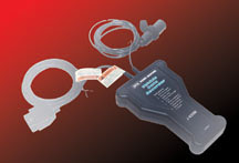
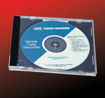
| Vehicle Data Recorder (VDR) Update |
Since
its introduction in 1998, the J-42598 Vehicle Data Recorder (VDR) has
been updated periodically to keep it current. This month, software version
7.0 is being released. It supports GM OBD II vehicles from 1995 1/2 through
2003. The tool itself is unchanged (fig. 13), but you will need to install the latest software on your TechLine terminal (fig. 14). The VDR is useful in instances where the customer’s vehicle is having an intermittent condition. To diagnose a condition like this, it’s helpful to have a snapshot of the data stream information at the moment the condition occurs. But to record a snapshot, it would be necessary to hook up your Tech 2 to the vehicle, train the customer which buttons to press when the condition occurred, and hope for the best. You’d also be without your Tech 2 while it was riding around in the customer’s car. The VDR was developed to eliminate all these objections. It’s a dedicated snapshot recorder. With the VDR properly programmed using your TechLine terminal, you can install the VDR in the customer’s car in place of your Tech 2. Then, when the condition occurs, all the customer has to do is press one button on the VDR to record the event. Up to four events can be recorded. Nothing could be simpler. Until now. DTC Trigger Setup With version 7.0, even the button press can be eliminated. That’s right. You can now program the VDR to trigger automatically. You can have it trigger on any diagnostic code, or you can specify up to 5 different codes of your own choice. The customer has to do absolutely nothing but drive the vehicle normally. TIP: Of course, you can still have the customer press the button if you determine that this is appropriate. Trigger Point Setup As before, you can specify the trigger point. It works like this. The VDR records data continuously as long as the vehicle is running. When the memory is full, the oldest data is dropped and new data is constantly added. When the trigger event occurs, the recorder takes in as much additional data as necessary to satisfy the trigger point you’ve specified. If you specify 0%, the recording is completed as soon as the trigger occurs. You will have a recording of only the data leading up to the event. If you specify 50%, half of the data will be before the trigger, and half of it will be after. And at 100%, all of the data will be after the trigger. Of course, you can choose any number between 0% and 100%. Data Collection Rate You can choose either Normal or Fast, to specify how many frames to capture during a recording. Data Parameter Groups The data parameters you can record are included within groups. You can view a list of the parameters contained within each group before making your decision. Playback and Display When the customer brings their vehicle and your VDR back, you can download the stored data for playback. The data will appear on your monitor just as though you were watching it on your Tech 2 while the vehicle was being driven. You can run the data back and forth, and replay it as necessary to determine the condition you’re looking for. If you wish, you can display the data in graphic form for additional analysis. And, you can save the data for future reference. Printing Data can be printed. You can specify the list of Diagnostic Codes. Or you can print a text version of the values of all the sensors and switches in the parameter group. Forward Compatibility In the past, data recorded on one version of software could not be played on other versions. Beginning with this version, data recorded in 7.0 will be playable in future software versions as well. User’s Manual A new updated user’s manual is now included on the CD supplied with this version of the software. A Summary of New Features The version 7.0 software offers several important new features: - 2003 vehicles included - Automatic trigger option - Future compatibility A Final Word The VDR is an excellent diagnostic aid. But it can do its job only if you choose to use it. Take a few minutes to locate the tool in your dealership. Then, read the user’s manual, and be prepared to put your VDR to work the next time you’re dealing with an intermittent condition. - Thanks to Mark Stesney and Mike Banar |
|||||||||||||||||||||||||||||||||||||||
| return to Table of Contents | ||||||||||||||||||||||||||||||||||||||||
|
|
||||||||||||||||||||||||||||||||||||||||
| Servicing Heated Seats |
Before
service replacement heat elements were developed for the vehicles listed
below, the only way to repair these vehicles’ failed heat element
was to replace the entire seat back or seat cushion trim cover.
*Soon to be released. |
|||||||||||||||||||||||||||||||||||||||
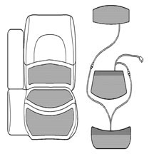 figure 16 |
||||||||||||||||||||||||||||||||||||||||
| return to Table of Contents | ||||||||||||||||||||||||||||||||||||||||
|
|
||||||||||||||||||||||||||||||||||||||||
| 3 Step Maintenance Fuel Induction Service Kit |
General
Motors has introduced a new 3 Step Maintenance Fuel Induction Service
Kit to the Vehicle Care product line. The GM part number is 12378546.
In Canada, the AC Delco part number is 88901364. Each kit includes three
containers: Fuel System Treatment, Induction Cleaner, and Throttle Body
Cleaner (fig. 17). The kits are available
from GMSPO and are sold by the case. One case contains enough cleaner
to service 12 vehicles. The three-step kit is designed to de-carbon engines and is intended for use with mileage-driven service menus. A typical customer comment may refer to rough idle. Tool Kit A tool kit (fig. 18) to apply the cleaning materials is also available from GMSPO, part number E-957-001. Maintenance Kit The maintenance kit includes three containers of cleaning solvents, each for a specific purpose. The Fuel System Treatment is to be poured into the fuel tank. It cleans the fuel system and fuel injectors, intake valves and combustion chamber. Clean fuel system components contribute to lower emissions. The Throttle Body Cleaner is packaged in a spray can and is used to clean the throttle body and lubricate the throttle plate. It also cleans the idle air control by-pass. This product is toluene-free and includes an ester oil lubricant. The Induction Cleaner cleans the front and back of the throttle body butterfly. It also cleans the intake plenum and runner, intake valves and combustion chamber. This product is toluene-free, so it is safe for seals and gaskets and will not harm plenum, catalytic convertors or oxygen sensors. Procedure Procedures are described in detail in the manual that accompanies the kit. The exact steps required vary depending on the type of fuel injection system on the vehicle. Generally, the procedure calls for three steps: - First, pour a bottle of Fuel System Treatment in the fuel tank. - Second, thoroughly clean the throttle body, using the Throttle Body Cleaner and a brush. -Third, apply a container of Induction Cleaner. Because of the various induction systems used on GM engines, the kit includes TBI sprayer tips (fig. 19), multiport S-sprayer tips (fig. 20), vacuum delivery adapters, and EGR adapter (fig. 21). Follow the appropriate instructions. The engine must be running, and some of the tools require the use of compressed air. - Thanks to Ron Caponey |
|||||||||||||||||||||||||||||||||||||||
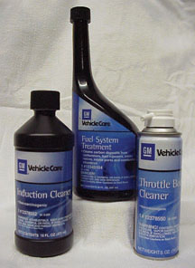 figure 17 |
||||||||||||||||||||||||||||||||||||||||
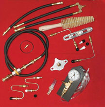 figure 18 |
||||||||||||||||||||||||||||||||||||||||
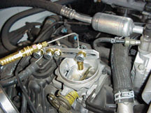 figure 19 |
||||||||||||||||||||||||||||||||||||||||
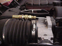 figure 20 |
||||||||||||||||||||||||||||||||||||||||
 figure 21 |
||||||||||||||||||||||||||||||||||||||||
| return to Table of Contents | ||||||||||||||||||||||||||||||||||||||||
|
|
||||||||||||||||||||||||||||||||||||||||
| Automatic Transmission DTC P0706 |
Some
Chevrolet and GMC trucks (C/K2500, C/K3500) equipped with 4L80E/4L85E
may set a DTC P0706 (Transmission Range Switch performance) and exhibit
a no-start condition. If this occurs, reprogram the PCM software using TIS2000 CD 9 or later. It is identified as New Calibration to Prevent Setting of DTC P0706. DTC P0706 can set falsely in unusual driving circumstances such as "bump starting" the vehicle. - Thanks to GM Technical Assistance |
|||||||||||||||||||||||||||||||||||||||
| return to Table of Contents | ||||||||||||||||||||||||||||||||||||||||
|
|
||||||||||||||||||||||||||||||||||||||||
| Cold Upshift Delay |
2002
Chevrolet Trailblazer, GMC Envoy and Oldsmobile Bravada equipped with
the 4L60E transmission may experience a delayed 1-2 upshift at a throttle
opening of 25% or less. The condition will occur when the engine coolant
temperature (ECT) is between 45°F (7°C) and 85°F (29°C)
at engine start-up. |
|||||||||||||||||||||||||||||||||||||||
| return to Table of Contents | ||||||||||||||||||||||||||||||||||||||||
|
|
||||||||||||||||||||||||||||||||||||||||
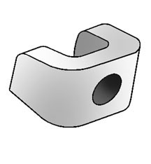
| Popping Noise While Turning |
Owners
of some 2002 Chevrolet Cavaliers or Pontiac Sunfires may comment that
they hear a popping type noise when turning the steering wheel (fig.
22). This noise is most easily replicated after a short drive on
uneven asphalt, then turning the vehicle left or right into a 90 degree
turn. The popping noise will occur only one time per turn. The condition may be caused by the stabilizer bar-to-suspension support brackets being out of specification (fig. 23). Replacement of the Stabilizer Bar Brackets is recommended to eliminate the noise associated with this condition. The part number for the bracket is 22660396. - Thanks to GM Technical Assistance |
|||||||||||||||||||||||||||||||||||||||
 figure 22 |
||||||||||||||||||||||||||||||||||||||||
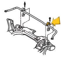 figure 23 |
||||||||||||||||||||||||||||||||||||||||
| return to Table of Contents | ||||||||||||||||||||||||||||||||||||||||
|
|
||||||||||||||||||||||||||||||||||||||||
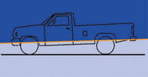
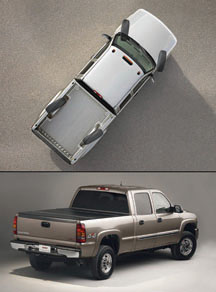
| Ride and Handling Concern | Owners
of some early built 2003 model year 1500 HD crew cabs (fig.
24) with Quadrasteer option ( NYS ) may comment about less than
optimal ride and handling characteristics (frame beaming, vehicle shake,
vibration). |
|||||||||||||||||||||||||||||||||||||||
| return to Table of Contents | ||||||||||||||||||||||||||||||||||||||||
|
|
||||||||||||||||||||||||||||||||||||||||
| Bulletins
- November, 2002 |
00
– General Information |
|||||||||||||||||||||||||||||||||||||||
| return to Table of Contents | ||||||||||||||||||||||||||||||||||||||||
|
|
||||||||||||||||||||||||||||||||||||||||
|
|
||||||||||||||||||||||||||||||||||||||||
|
|
|
|||||||||||||||||||||||||||||||||||||||
|
|
|
|||||||||||||||||||||||||||||||||||||||