
Note: Click a picture or illustration in the left column to view a large version in the article.
To hide the large version, simply click on it. |
||||||||||||||||||||||||||||||||||||||||||||||||||||||||
|
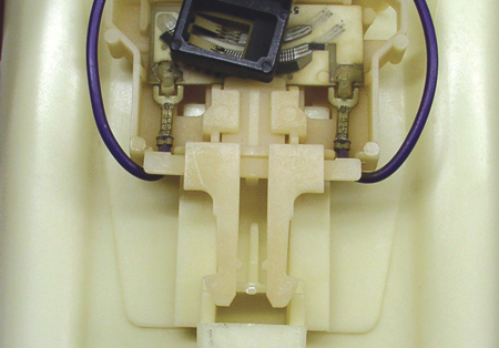
Fuel Pump Modular Reservoir Assembly |
A recall bulletin 05-027 is being prepared to cover 2000-01 Chevrolet Suburban and GMC Yukon XL (excluding 2500 HD). The
terminals in the 4-wire electrical connector at the top of the fuel pump
assembly may experience fretting and high resistance.
TIP: Fretting was explained in the June 2003 TechLink.
The bulletin explains how to install a repair kit 15824379
to the fuel pump assembly. It contains replacement electrical connectors, a
replacement fuel level sensor, related hardware and instructions.
Installing replacement connector components in the cover
is a new procedure. The kit installation also requires replacing the fuel
level sensor, which is an existing SI procedure. However, in this repair, you
will re-use the float assembly, which is a new procedure.
Refer to the bulletin, the kit instructions, and related
SI procedures for the details in performing the installation of the kit. Here
are some highlights and tips to help you install the new components
correctly.
TIP: You are instructed to remove and discard the fuel
pump fuse. A replacement is included in the kit. Using a new fuse is a
precaution.
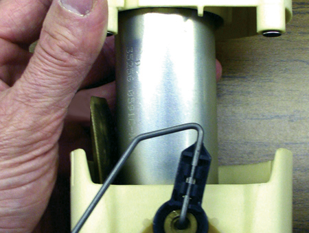
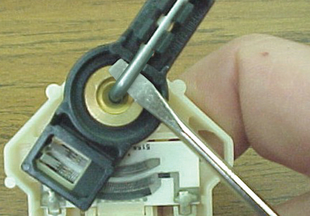
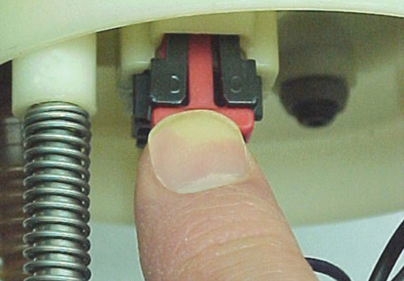
The electrical connector that passes through the cover is
retained by a lock tab, which you can loosen with finger pressure (fig. 4).
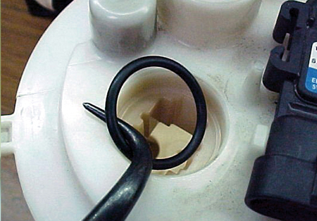
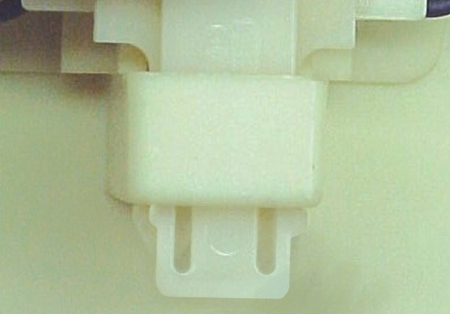
TIP: After removing the connector, be sure the O-ring does
not remain in the cover (fig. 5).
Observe these precautions to ensure a proper seal of the
new connector and new O-ring in the cover.
- Be sure all dirt and debris are cleared from the cover.
IMPORTANT: The O-ring may be damaged during installation
if it is not properly lubricated.
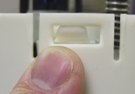
IMPORTANT: Be sure the connector is properly aligned with
the opening in the cover, then use finger pressure to install the connector
into place until the tab clicks. Check the connector for proper installation (fig. 7).
Typically, the float arm and fuel level sensor are
replaced as a unit. In this procedure, you must remove the float arm from the
sensor and re-use it.
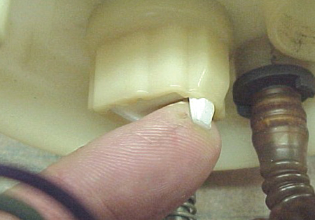
TIP: When installing the new fuel level sensor to the
reservoir, be sure the tabs on the sensor align with the slots in the
reservoir (fig. 9).
Match the wire colors and splice the new 4-pin GT 280
connector to the vehicle harness.
TIP: There are two colors of splices in the kit. The blue splices are for the black and grey wires, and the red splices are for the purple and orange/black wires. TIP: Use the appropriate crimp tool J-38125-8. TIP: After crimping, heat each splice until sealant comes
out of both ends of the tube.
- Thanks to Charley Gipe and Dave Roland |
|||||||||||||||||||||||||||||||||||||||||||||||||||||||
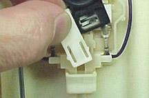 figure 1 |
||||||||||||||||||||||||||||||||||||||||||||||||||||||||
 figure 2 |
||||||||||||||||||||||||||||||||||||||||||||||||||||||||
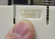 figure 3 |
||||||||||||||||||||||||||||||||||||||||||||||||||||||||
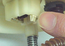 figure 4 |
||||||||||||||||||||||||||||||||||||||||||||||||||||||||
 figure 5 |
||||||||||||||||||||||||||||||||||||||||||||||||||||||||
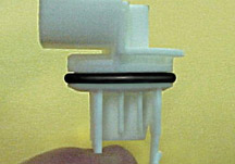 figure 6 |
||||||||||||||||||||||||||||||||||||||||||||||||||||||||
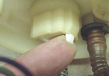 figure 7 |
||||||||||||||||||||||||||||||||||||||||||||||||||||||||
 figure 8 |
||||||||||||||||||||||||||||||||||||||||||||||||||||||||
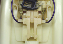 figure 9 |
||||||||||||||||||||||||||||||||||||||||||||||||||||||||
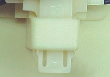 figure 10 |
||||||||||||||||||||||||||||||||||||||||||||||||||||||||
 figure 11 |
||||||||||||||||||||||||||||||||||||||||||||||||||||||||
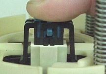 figure 12 |
||||||||||||||||||||||||||||||||||||||||||||||||||||||||
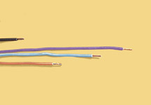 figure 13 |
||||||||||||||||||||||||||||||||||||||||||||||||||||||||
|
|
||||||||||||||||||||||||||||||||||||||||||||||||||||||||
| GM Multiple PC
Initiative Hardware Update
|
Dealers who purchased HP products from a Regional Techline
Consultant as part of the GM Multiple PC Initiative will find they have
world-class support available to them if they need it. In addition to the
Techline Customer Support Center (TCSC), dealers also have the HP help desk
available for hardware warranty support.
TIP: Call TCSC first. They will help determine what type
of problem you are experiencing. If the issue is HP hardware related, use the
following support process.
Call the HP exclusive GM Dealership support number
(1.800.925.8245).
Prompts:
- (Option 1) Desktop
- (Option 2) Note book
- (Option 3) Printer
- (Option 4) All other products
Once you provide a serial number, the HP technician will
be able to identify that you are from a GM dealership.
IMPORTANT: The HP technician taking the initial dealer
call will follow a standard list of trouble shooting techniques that are used
to diagnose the problem. As part of the call resolution process, the HP
technician may escalate the call to an advanced team if necessary.
You also have the option to request your call be escalated
to the advanced team. Be sure to indicate that you are making an Advanced
Team Escalation request. This may be an appropriate avenue for dealer system
administrators who have already completed the initial diagnostic and
troubleshooting steps on their own. Be prepared to list the troubleshooting steps that have already taken
place and the results.
-
Thanks to Mike Waszczenko
|
|||||||||||||||||||||||||||||||||||||||||||||||||||||||
| return to Table of Contents | ||||||||||||||||||||||||||||||||||||||||||||||||||||||||
|
|
||||||||||||||||||||||||||||||||||||||||||||||||||||||||
| Revised Lifting and
Jacking Procedure
|
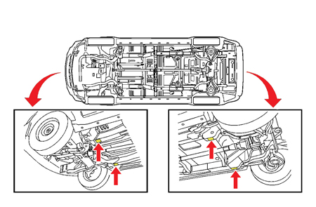
Bulletin 05-00-89-027 contains important information on
how to lift or jack the 2005-06 Equinox and Torrent.
The lift or jack pads must be located inboard from the
pinchweld flanges (fig. 14), as specified in
the bulletin, to avoid damage to the pinchweld flanges.
-
Thanks to Jerry Garfield
|
|||||||||||||||||||||||||||||||||||||||||||||||||||||||
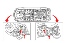 figure 14 |
||||||||||||||||||||||||||||||||||||||||||||||||||||||||
|
|
||||||||||||||||||||||||||||||||||||||||||||||||||||||||
Tech 2 Progress Bar
|
Programming Alert: Depending on which calibrations are
being updated, the progress bar on your Tech 2 may NOT display 100%, even
though programming is complete. Some complete programming events may display
as little as 5% on the progress bar before displaying the Programming
Successful screen. This condition is normal.
TIP: If you see the Programming Successful message, the
programming event is complete. Do NOT replace the ECM.
This alert applies to all vehicles equipped with the E35,
E37, E38, E55 and E67 ECMs and the Allison LCT1000 Six Speed TCM. These ECMs
are being used in selected 2004-06 and future vehicles.
TIP: Look for a spread sheet of vehicle coverage on the
TechLink website Reference Guide.
TIP: These guidelines will also apply to Body and Chassis
ECUs in some current and future vehicles.
- Thanks to Mark Stesney, BQM / Tech 2 / TechLink |
|||||||||||||||||||||||||||||||||||||||||||||||||||||||
|
||||||||||||||||||||||||||||||||||||||||||||||||||||||||
|
|
||||||||||||||||||||||||||||||||||||||||||||||||||||||||
| Hybrid Truck Followup
|
Here are some additional cautions to observe when working
on a Chevrolet or GMC Hybrid Truck (TechLink, October 2005).
CAUTION: To reduce the risk of severe shock and
burns, disable the 42 volt
(42V) system any time you perform service work on or
around the energy storage box (ESB). The 42V system will still be active
after you have disabled the ESB.
CAUTION: To reduce the risk of severe shock and
burns, always treat the 3-phase cable and connectors as if voltage is present
and as if the surface of all parts of the cable is hot.
- Thanks to Doug Ritter and Stephen Cichy
|
|||||||||||||||||||||||||||||||||||||||||||||||||||||||
|
||||||||||||||||||||||||||||||||||||||||||||||||||||||||
|
|
||||||||||||||||||||||||||||||||||||||||||||||||||||||||
Headlamp Harness for XLR |
The following part numbers have been issued by GM Service Engineering to enable the use of 2006 production headlamps on 2004-05 Cadillac XLR vehicles.
|
|||||||||||||||||||||||||||||||||||||||||||||||||||||||
|
|
||||||||||||||||||||||||||||||||||||||||||||||||||||||||
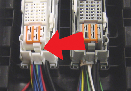
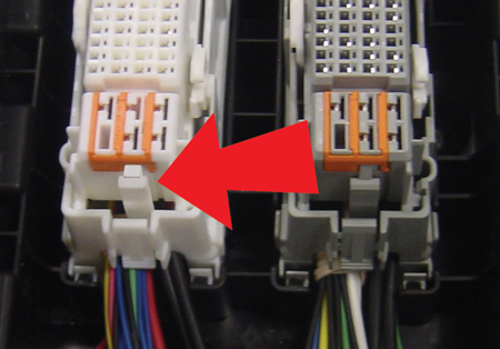
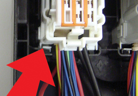
| Underhood Accessory Wiring Junction Block |
Here are some tips to help avoid damage when working on the Underhood Accessory Wiring Junction Block (also called the UBEC) on the Hummer H3. If there is downward movement, use a hook tool or your hand to pull the connector up to the pre-staged position (fig. 16). You will hear a click. Then recheck the pre-staging. Servicing Levers If there is damage to the connector levers, there is no need to replace the complete connector (which would require removing and installing all the related terminals). Simply swap the levers from a service replacement connector to the one with the broken levers. Begin by removing the connector from the mounting cover. Remove the most inboard locking tab (fig. 17) first and then the two most outboard locking tabs (fig. 18). Then remove the connector from the housing. Remove the connector's right-angle dress. Then release the connector pre-stage tabs to lower the connector to the bottom of the housing. Pry outward on the connector housing at all four corners to release the connector. Install the levers from the replacement connector. Then reassemble.
|
|||||||||||||||||||||||||||||||||||||||||||||||||||||||
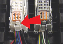 figure 15 |
||||||||||||||||||||||||||||||||||||||||||||||||||||||||
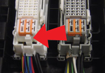 figure 16 |
||||||||||||||||||||||||||||||||||||||||||||||||||||||||
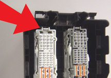 figure 17 |
||||||||||||||||||||||||||||||||||||||||||||||||||||||||
 figure 18 |
||||||||||||||||||||||||||||||||||||||||||||||||||||||||
| return to Table of Contents | ||||||||||||||||||||||||||||||||||||||||||||||||||||||||
|
|
||||||||||||||||||||||||||||||||||||||||||||||||||||||||
|
Titanium Engine Parts |
The connecting rods and intake valves used in the Corvette Z06 LS7 engine are made of titanium. |
|||||||||||||||||||||||||||||||||||||||||||||||||||||||
|
||||||||||||||||||||||||||||||||||||||||||||||||||||||||
| return to Table of Contents | ||||||||||||||||||||||||||||||||||||||||||||||||||||||||
|
|
||||||||||||||||||||||||||||||||||||||||||||||||||||||||
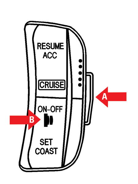
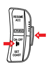
| Cruise Control Operation |
This information applies to the 2006 Aveo and Wave, and the 2004-06 Optra. Pressing the SET/COAST switch when the ON-OFF switch is not in the ON position will not activate the cruise control system. - Thanks to John Bowman |
|||||||||||||||||||||||||||||||||||||||||||||||||||||||
| return to Table of Contents | ||||||||||||||||||||||||||||||||||||||||||||||||||||||||
|
|
||||||||||||||||||||||||||||||||||||||||||||||||||||||||
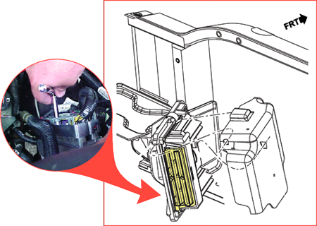
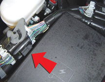
PCM Connectors |
This information applies to 2003-06 full-size pickups and utilities. - Thanks to Bob Vandenbush and Tim Tang |
|||||||||||||||||||||||||||||||||||||||||||||||||||||||
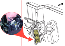 figure 20 |
||||||||||||||||||||||||||||||||||||||||||||||||||||||||
| return to Table of Contents | ||||||||||||||||||||||||||||||||||||||||||||||||||||||||
|
|
||||||||||||||||||||||||||||||||||||||||||||||||||||||||
|
Hydraulic Brake Assist Service Information Update |
The following vehicles have updated hydraulic brake assist service information: |
|||||||||||||||||||||||||||||||||||||||||||||||||||||||
| return to Table of Contents | ||||||||||||||||||||||||||||||||||||||||||||||||||||||||
|
|
||||||||||||||||||||||||||||||||||||||||||||||||||||||||
| How to Find DTCs in Service Information | In the early days of computerized vehicle systems, the only thing controlled by an electronic module was the engine functions. All diagnostic codes in existence at that time were engine related. |
|||||||||||||||||||||||||||||||||||||||||||||||||||||||
| return to Table of Contents | ||||||||||||||||||||||||||||||||||||||||||||||||||||||||
|
|
||||||||||||||||||||||||||||||||||||||||||||||||||||||||
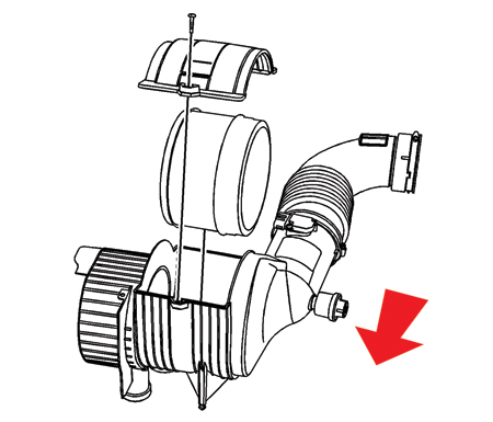
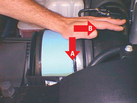
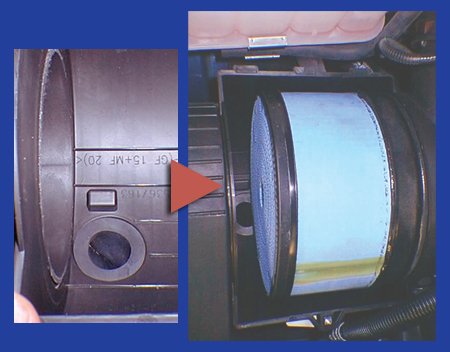
| Air Filter Installation |
Here’s a tip for installing the air filter element on a 2006 C/K truck with Duramax diesel engine. Press both downward and inboard until the outboard end of the element clicks into place inboard of the locating tab (fig. 23). - Thanks to Mathew Gray
|
|||||||||||||||||||||||||||||||||||||||||||||||||||||||
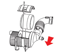 figure 21 |
||||||||||||||||||||||||||||||||||||||||||||||||||||||||
 figure 22 |
||||||||||||||||||||||||||||||||||||||||||||||||||||||||
 figure 23 |
||||||||||||||||||||||||||||||||||||||||||||||||||||||||
| return to Table of Contents | ||||||||||||||||||||||||||||||||||||||||||||||||||||||||
|
|
||||||||||||||||||||||||||||||||||||||||||||||||||||||||
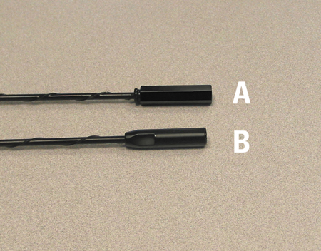
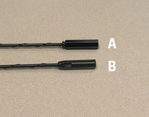
| Fixed Mast Antenna | A new AM/FM fixed mast antenna is being used on 2006 full size trucks and utilities, and the TrailBlazer/Envoy. The new antenna features a 7mm stud on the antenna base, in place of the 6mm stud of the previous design. TIP: The mast no longer comes with a plastic wrench. Use hand tools to install. When installing any fixed mast antenna to the base, tighten until the mast is fully seated, then take an additional quarter turn. Be careful not to chip the coating on the antenna. - Thanks to Jim Will and Jim Hughes |
|||||||||||||||||||||||||||||||||||||||||||||||||||||||
| return to Table of Contents | ||||||||||||||||||||||||||||||||||||||||||||||||||||||||
|
|
||||||||||||||||||||||||||||||||||||||||||||||||||||||||
| OnStar Relaxes Requirement | Beginning December 1, 2005, OnStar will no longer require service technicians to contact General Motors Technical Assistance to obtain parts for many of its early generation OnStar systems. A Service Bulletin and Preliminary Information documents will be published to provide a comprehensive list of the part numbers which can be ordered without a call to Technical Assistance. |
|||||||||||||||||||||||||||||||||||||||||||||||||||||||
| return to Table of Contents | ||||||||||||||||||||||||||||||||||||||||||||||||||||||||
|
|
||||||||||||||||||||||||||||||||||||||||||||||||||||||||
| Turbine Shaft Usage | This information applies to all 2006 Cadillac, Chevrolet and GMC Full-Sized Trucks and Utilities, Buick, Chevrolet, GMC Mid-Sized Trucks and Utilities, Hummer H2 and H3,and Pontiac GTO with 4L60E (RPO - M30) or 4L65E (RPO - M32) or 4L70E (RPO - M70) Transmission. |
|||||||||||||||||||||||||||||||||||||||||||||||||||||||
| return to Table of Contents | ||||||||||||||||||||||||||||||||||||||||||||||||||||||||
|
|
||||||||||||||||||||||||||||||||||||||||||||||||||||||||
| Loose Connection | This condition could affect 2004-06 Buick Rainier, Chevrolet Trailblazer, and GMC Envoy, 2002-04 Oldsmobile Bravada and 2005-06 Saab 97x. TIP: When servicing this connector, be careful not to damage other terminals. Fully seat the connector squarely with both hands and then latch the locking portion of the connector (CPA). Do not use the lock mechanism on the connector to pull the connector halves together, as this may cause terminals to bend or make a poor connection. - Thanks to Dino Poulos |
|||||||||||||||||||||||||||||||||||||||||||||||||||||||
| return to Table of Contents | ||||||||||||||||||||||||||||||||||||||||||||||||||||||||
|
|
||||||||||||||||||||||||||||||||||||||||||||||||||||||||
| Roof Beacon Switch | On some 2003-06 Chevrolet Avalanche and Silverado and GMC Sierra vehicles, the battery may be discharged for no apparent reason. |
|||||||||||||||||||||||||||||||||||||||||||||||||||||||
| return to Table of Contents | ||||||||||||||||||||||||||||||||||||||||||||||||||||||||
|
|
||||||||||||||||||||||||||||||||||||||||||||||||||||||||
 Car Issues
— Fix It Right the First Time (new issues in bold) Car Issues
— Fix It Right the First Time (new issues in bold) |
||||||||||||||||||||||||||||||||||||||||||||||||||||||||
|
||||||||||||||||||||||||||||||||||||||||||||||||||||||||
| return to Table of Contents | ||||||||||||||||||||||||||||||||||||||||||||||||||||||||
|
|
||||||||||||||||||||||||||||||||||||||||||||||||||||||||
|
||||||||||||||||||||||||||||||||||||||||||||||||||||||||
|
||||||||||||||||||||||||||||||||||||||||||||||||||||||||
| return to Table of Contents | ||||||||||||||||||||||||||||||||||||||||||||||||||||||||
|
|
||||||||||||||||||||||||||||||||||||||||||||||||||||||||
|
Know-How Broadcasts for JANUARY |
|
|||||||||||||||||||||||||||||||||||||||||||||||||||||||
|
||||||||||||||||||||||||||||||||||||||||||||||||||||||||
|
|
||||||||||||||||||||||||||||||||||||||||||||||||||||||||


 Truck Issues — Fix It Right the
First Time (new issues in bold)
Truck Issues — Fix It Right the
First Time (new issues in bold)
