| |

|
Note: Clicking
on any picture or illustration will open a larger version of that art.
|
|
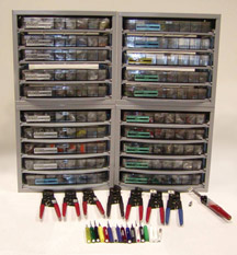
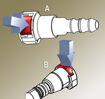
Terminal
Repair Kit Update J-38125-710 |
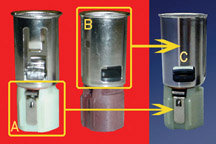
This continuing
information will help you understand the J-38125-D Terminal Repair Kit
and use it more effectively (fig. 1). This
information supplements the TechLink article published in September
2002.
Some Definitions
An electrical terminal is the formed metal attached to the end of a
wire to provide electrical connection with another wire or with a component.
Groups of terminals are organized into molded plastic blocks called
connectors.
Groups of wires, with their terminals and connectors, are gathered into
wiring harnesses.
Production vs. Service Terminals
TIP: There are
differences between production terminals and service terminals. A single
service terminal may replace several production terminal numbers.
Service terminals are chosen so the crimp wings fit the crimp tools
in the J-38125-D kit. You should use the crimp matrix in the Terminal
Repair Kit instruction book for best results.
Service terminals may have more tin or gold content than the production
terminal.
Service terminals may have a higher contact force than the production
terminal. In the assembly plant, where actions are repetitive, connector
assembly effort is an issue that does not come up in service.
Where Do Service Terminals Come From?
Service terminals are NOT available from GMSPO. A parts bulletin IB03-044
has been issued to this effect. There have been many ParTec orders placed
in error because of this.
Because service terminals are not stocked by GMSPO, the service terminals
in the J-38125-D Terminal Repair Kit have supplier part numbers.
All service terminals and all components and tools of the J-38125-D
Terminal Repair Kit should be ordered from SPX (Kent-Moore) at 1.800.345.2233.
It is important to keep the complete J-38125-D Terminal Repair Kit in
proper order and stocked with terminals and tools, as more wiring suppliers
make their appearance in GM vehicles.
How Are Terminals Organized in the J-38125-D Terminal Repair
Kit?
There are five wiring suppliers for GM Power and Signal Distribution
(PASD) systems:
- AFL
- Delphi
- Lear
- Sumitomo
- Yazaki.
These five supply the wiring used in North American-engineered platforms.
The J-38125-D Terminal Repair Kit was originally a Delphi terminal repair
kit only. There are now Delphi trays, Lear trays, Sumitomo trays and
Yazaki trays, with AFL to be added in 2005.
The 2003 Up-Date (J-38125-710)
You have just received the 2003 J-38125-710 up-date to the J-38125-C
Terminal Repair Kit, making it now the J-38125-D Terminal Repair Kit.
This is perhaps the largest up-date to the base J-38125 Terminal Repair
Kit to date. The reason is to add all the new service terminals now
in GM vehicles that have not been serviced since 1998.
The up-date consists of eight new trays of terminals, numbered 7, 14,
15, 16, 17, 18, 19 and 20. Tray 7 has been filled with new terminals
and replaces the existing Lear tray 7.
TIP: You may
want to organize your Terminal Repair Kit by supplier (without regard
to tray numbers): e.g. Delphi, Lear, Sumitomo and Yazaki.
You will also receive three new terminal release tools. The J-38125-24
green tool is for a very small Tyco terminal found at some sunroof and
door modules. The J-38125-211 blue tool is for a JAE terminal found
in some steering column connectors. The J-38125-212 green tool is for
a Tyco male JPT terminal found in some engine harnesses.
There four cable seals to add to Yazaki tray 13.
The reference guide is completely new and has a complete inventory of
the J-38125-D Terminal Repair Kit.
Additional guides can be ordered from SPX (Kent-Moore) under p/n J-38125-620.
Finally, there are new tray labels for the first five Delphi trays and
Delphi tray eight.
Setting Up Your Trays
Take your time getting the old labels off, cleaning the tray lids and
carefully positioning the new labels on the tray lids so the terminals
are correctly identified.
These new tray labels are very important, because a number of old terminals
have been replaced or deleted. The new tray labels provide two pieces
of information.
- The new service terminal part number.
- The tray in which it is stocked.
There is also a small stick-on label for tray 13, identifying the new
cable seals in this up-date.
The metal cabinets that hold the terminal trays can also be ordered
from SPX (Kent-Moore) under p/n J-38125-610. The J-38125-710 up-date
will fill four of these cabinets. If you have some of the tool trays,
you may need a fifth cabinet. You can use tool trays to hold the terminal
release tools and Ultratorch.
A Word About the Terminal Test Kit J-35616-B
A number of test probes are added to the J-35616-B Terminal Test Kit,
due to the number of new terminals in the J-38125-D Terminal Repair
Kit. (fig. 2)
There has never been a good way of relating any given terminal to its
proper test probe. So with this up-date, all terminal descriptions will
have within them a terminal size: e.g., M/P 150 series male. The 150
will now relate directly to a 150 test probe. The test probe will be
called the 150 male probe adaptor – gray.
All the test probes will be renamed and a new label will be sent with
the up-date for the J-35616-B Terminal Test Kit in 2004. The J-35616-B
Terminal Test Kit will then become the J-35616-C Terminal Test Kit.
What’s Coming?
Under consideration for 2004 is an AFL service terminal tray, along
with new Sumitomo service terminals to the existing Sumitomo tray 6.
Additional Sumitomo trays may be added at that time.
There should not be a need for any new crimp tools in 2004.
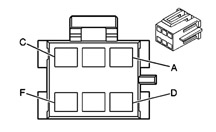
Information included in SI is being revised. A pilot for a new connector
end view is planed for the ‘04 Cadillac XLR service information.
This connector end view will give you the service terminal number that
is in the J-38125-D Terminal Repair Kit.
TIP: The new
connector end view (fig. 3) will for the
first time give you the real connector or pigtail part number, which
is stocked by GMSPO. This connector end view may take some time to make
its appearance in all the service information, but every effort is being
made to do so.
-
Thanks to John Roberts and Jim Willockx |
|
figure
1 |
|
|
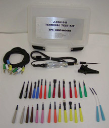
figure 2 |
figure
3
|
| return
to Table of Contents |
|
|
| VCI
Number |
Let’s begin with a definition. A Vehicle Configuration Index (VCI)
is a number assigned to a valid calibration or group of calibrations
for each module for a specific vehicle that is programmed using the
Service Programming System (SPS). Each VCI represents a specific vehicle
configuration. Multiple VCI numbers can be assigned to the same Vehicle
Identification Number (VIN) based on the number of SPS programmable
modules on the vehicle. When programming using a VCI number, keep in
mind that it is valid only for the vehicle and control module that it
is issued for, and cannot be used to program another vehicle with the
same configuration.
TIP: Also VCI
numbers will always take you to the latest calibration or group of calibrations
available in TIS.
When the vehicle leaves the assembly plant, a database has already been
created for it. This is called the “as-built” data. At that
time, VCI numbers are assigned to each VIN and control module based
on variables such as engine type, transmission type, tire size, axle
ratio, etc.
If a dealer adds certain equipment to a vehicle, or changes certain
equipment on a vehicle, the “as-built” data are no longer
representative of the vehicle. So, it is necessary to obtain a new VCI
number to represent the “as-is” content of the vehicle.
An example is installing an optional wheel/tire size.
TIP: It is necessary
to call the Techline Customer Support Center (TCSC) at 1.800.828.6860
to change a vehicle’s VCI.
TIP: For a given
vehicle, it is possible to obtain VCI numbers only for combinations
of components and specifications approved by General Motors.
Important Benefit of the VCI Number
The VCI concept provides an important benefit to dealers: the reconfiguration
history of a vehicle does not need to be known before programming. It
works like this. If a vehicle’s content is changed, requiring
module reprogramming, a different VCI number is needed before the Techline
terminal and Tech 2 can be used. Only TCSC can issue VCI numbers. When
TCSC issues a new VCI number for a vehicle, the changes made to the
vehicle now become a part of the vehicle’s VIN data record. Once
the database has been updated, subsequent Techline releases will contain
the new information and a VCI number will no longer be required.
20 Inch Wheel and Tire Example
As explained in the January 2004 issue of TechLink, Chevrolet and GMC
dealers can now obtain accessory wheels and tires from SPO and install
them on certain trucks. Refer to bulletin 03-03-10-006 for specific
details and exceptions.
Because these wheels and tires are larger than the standard ones, it
is necessary to recalibrate the PCM and ABS modules.
In order to reprogram the PCM, a new VCI number must be input. The dealer
has to call TCSC to obtain it. At that time, TCSC modifies the vehicle’s
database to reflect the new wheel and tire size.
IMPORTANT: Because this is not a warranty procedure, but is
customer paid, TCSC charges a fee for this service.
TIP: In the future,
if original equipment size wheels and tires are again installed on the
vehicle, it is necessary to contact TCSC, to obtain the necessary VCI
number to recalibrate the vehicle again.
-
Thanks to Dave Puzzuoli and Mark Stesney |
|
|
|
| Fuel
Sender Lock Rings |
GM
Fuel Systems has developed a common fuel sender closure (lock ring)
which will be implemented on most GM vehicles beginning in model year
2004.
The tool needed to properly service this closure is J-45722 (fig.
4).
Because the removal and installation forces are higher than typical,
use a long breaker-bar with J-45722. Have an assistant secure the fuel
tank if necessary.
TIP: The lock
ring and tool will rotate approximately 16 degrees. Ensure that the
J-45722 is positioned so as to prevent damage to the fuel sender when
unlocking or locking the system.
TIP: Any time
the fuel sender closure is opened, the fuel sender closure seal must
be replaced.
SI procedures are being revised to reflect this change.
- Thanks to Kevin Willcock |
| 
figure
4
|
return to Table of Contents |
|
| Wiper
Blade Optimizer |
Effective
immediately, the assembly plant will be putting two Optimizer pads in
the glove compartment of each 2004 Venture, Silhouette, and Montana.
The Optimizer is a wiper blade element cleaning pad. It uses a specific
Isopropanol-based formula to remove wax, dirt, and other contaminants
from the wiper blade element.
Wiper blade elements all contain wax in the rubber to prevent cracking
or deterioration under the effects of ozone, heat and sunlight. It is
normal for some of this wax to slowly bleed out over time.
TIP: The wax-removing,
cleaning effect has the most impact when performed just before delivery
of the vehicle to the customer. Because the PDI process may be done
well in advance of delivery, please ensure that this wiper blade cleaner
is applied during the final wash and prep just before delivery.
-
Thanks to Tom Geist |
| |
| return
to Table of Contents |
|
| Elimination
of LH Hood Assist Rod |
The
number of hood assist rods has been reduced from two to one on the 2004
Cadillac CTS. Vehicles built after VIN breakpoint 40137492 will feature
a high pressure single hood assist rod located on the RH side.
TIP: Any attempts
to modify or add an additional hood assist rod could result in damage
to the vehicle.
-
Thanks to Terry Bordeau |
| |
| return
to Table of Contents |
|
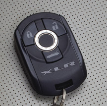
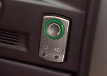
| XLR
Keyless Ignition |
The
Cadillac XLR keyless access system does not use a traditional key for
door locks or ignition. Instead, the driver carries a transmitter fob
(fig. 5). When the vehicle senses the presence
of the correctly coded transmitter fob, the doors can be opened. With
the transmitter fob inside the passenger compartment, the engine can
be started by pressing the START button on the instrument panel (fig.
6).
Key On, Engine Off Mode
There may be times, such as when you are performing diagnostics on the
vehicle, that you need to have the ignition turned on, with the engine
not running. In this mode, all modules are powered up and communicating
on the serial data line.
TIP: This information
is covered in SI. Follow this path: Accessories > Keyless Entry >
Description and Operation > Keyless Entry System Description and
Operation
- Make sure the transmitter fob is inside the passenger compartment.
- Depress the brake pedal.
- Be sure the transmission is in Park or Neutral.
- Press the ACC button and hold for 5 seconds. The instrument panel
will light up and the ignition will be turned on, but the engine will
not start.
TIP: If you press
the ACC button only briefly, the accessory mode will be turned on. This
is not the same as turning the ignition on.
It is imperative that you press ACC again to turn the ignition off.
TIP: Retained
Accessory Power will function for 10 minutes after the ignition is turned
off, or until a door is opened.
-
Thanks to Brad Thacher |
figure
5 |
figure
6 |
| return
to Table of Contents |
|
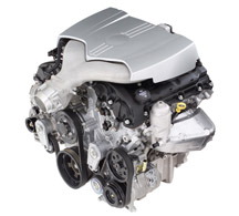
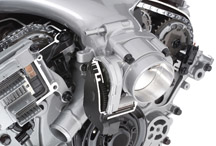
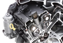
| 3.6L
V-6 VVT Engine (RPO LY7) |
For
2004, GM Powertrain has introduced an all-new 60° DOHC V-6 engine
(fig. 7). It will initially be used in
the Cadillac CTS and SRX and the Buick Rendezvous. This engine offers
contemporary world-class features:
- all-aluminum construction
- dual overhead camshafts (DOHC)
- 4-valves per cylinder
- roller-finger follower valvetrain
- continuously variable cam phasing
- electronic throttle control
- forged-steel crankshaft
- piston-cooling oil jets
- Oil Life System
- 32-bit microprocessor
- coil-on-plug ignition
Design Philosophy
This 60° DOHC V-6 engine was developed by GM technical centers in
Australia, Germany, North America and Sweden for global application
in premium and high-performance vehicles. It applies the most advanced
technology available. The modular design assures multiple displacement,
configuration and content possibilities. The result is an engine that
delivers good specific output, high torque over a wide rpm range, fuel
economy, low emissions, excellent noise, vibration and harshness (NVH)
control, durability, and low maintenance requirements.
Although the initial offering will be 3.6L displacement, variants can
be manufactured in 2.8L, 3.2L and 3.8L sizes. Power will range from
200 to 370 hp, while torque will run from 200 lb-ft to more than 350
lb-ft. The 3.6L will provide 255 hp and 250 lb-ft of torque.
The engine was designed to be installed in multiple orientations:
- front-wheel drive, typically transverse
- rear-wheel drive, typically longitudinal
- all-wheel drive, either transverse or longitudinal
Manufacturing
The DOHC V6 engines will be built in GM Powertrain facilities in Port
Melbourne, Victoria, Australia and St. Catherines, Ontario, Canada.
Initially, rear-wheel drive engines will be built in Canada and front-wheel
drive engines will be built in Australia.
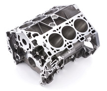
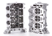
Block and Heads
The engine block and cylinder heads are cast of A319 aluminum alloy,
for lower weight. This translates to improved fuel economy. Math-based
structural analysis permits maximum performance and durability with
minimum mass.
The block is cast using the precision sand-mold method, with iron cylinder
bore liners in place (fig. 8). Precision
casting reduces the need for machining, and reduces material waste.
Attachment points are included for all drive configurations in all castings,
and are machined as needed depending on application.
The 60° cylinder arrangement provides for smooth, vibration-free
operation without the balance shafts typically needed in 90° V6s.
Vibration is further limited by the deep-skirt design. Sintered steel
main bearing caps are attached with six bolts, a premium feature.
The heads are cast in semi-permanent molds (fig.
9). Inlet passages are designed for optimum airflow, for reduced
operating noise. Exhaust ports allow maximum flow, while preserving
heat for quick catalyst light-off.
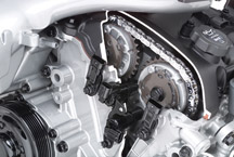
Valvetrain
The LY7 has fully variable valve timing for both intake and exhaust.
This electronically controlled, hydraulically operated system places
a phaser on each of the four camshafts (fig. 10).
The phaser enables changing the timing of the camshaft relative to the
crankshaft, over a range of 50° of crankshaft rotation. Fixed camshafts
compromise between smooth idle, good low-rpm torque and high-rpm power.
Variable camshaft timing accommodates the sometimes divergent needs
for power, driveability, economy and emission control.
At idle, the exhaust cams operate at full advance, for minimum valve
overlap. Optimizing valve overlap eliminates the need for a separate
exhaust gas recirculation (EGR) system and air injection reaction (AIR).
By closing the exhaust valves late, at the appropriate times, the desired
amount of exhaust gas is forced back into the combustion chamber for
burning in the next cycle.
The camshafts are driven by a roller chain. A hydraulically operated
tensioner keeps proper tension on the chain, even as it stretches with
mileage (a normal occurrence in all chains), which eliminates need for
periodic replacement or adjustment.
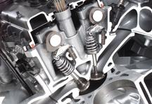
The cams operate directly on roller-finger followers (fig.
11), which actuate the valves. Hydraulic lash adjusters provide
automatic adjustment.
TIP: Setting
the camshaft timing is necessary whenever the camshaft drive system
has been disturbed such that the relationship between any chain and
sprocket has been lost. Even when only one sprocket is involved, multiple
crankshaft rotations will not produce conditions where correct timing
can be confirmed. Refer to the complete procedure in SI. Follow the
left bank secondary camshaft drive chain replacement procedures to reset
the camshaft timing.
Variable Intake Manifold and Electronic Throttle
The variable cam timing is supplemented by a dual-stage variable intake
manifold (VIM) (fig. 12). When the VIM
switch is shut, at low and mid speeds, the cylinders feed from two separate
plenums. At higher speeds, the switch opens, causing the cylinders to
feed from a single common plenum, boosting cylinder charging. Because
the intake runners are all precisely the same length, airflow is consistent
to all cylinders. This reduces the intake noise sometimes associated
with high-revving engines.
The electronically controlled throttle (ECT) eliminates the traditional
throttle cable between the pedal and the throttle body. Driver input
is registered by a throttle position sensor at the pedal, and precision
throttle rate and angle are provided by a computer-controlled stepper
motor (fig. 13). The ECT also incorporates
cruise control, which eliminates components, wiring, and complexity.
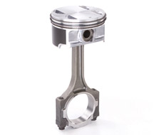
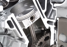
Pistons and Crankshaft
Pistons are manufactured of forged aluminum, which is lighter than conventional
steel pistons (fig. 14). Reduced mass provides
greater operating efficiency and reduced noise and harshness.
The full-floating 24-mm wristpins are retained in the pistons by snap
rings, but are otherwise free to float in both the piston and connecting
rod. This permits tighter tolerances and reduces friction and operating
noise.
Pistons are coated with polymer, applied to the skirts. This reduces
bore scuffing, despite reduced piston-to-bore clearances.
An oil jet sprays the underside of each piston and surrounding cylinder
wall, for reduced friction and extra cooling (fig.
15).
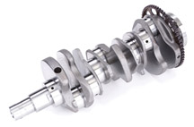
The crankshaft is forged steel, which is inherently stiffer than cast
iron, for reduced vibration (fig. 16).
The crankshaft sprocket is cushioned with a molded-rubber ring. And
the crank seals are made of Teflon, which is impervious to oil and gases.
Electronics
A single microprocessor (fig. 17), mounted
directly to the engine, manages numerous functions:
- cam phasing
- electronic throttle
- torque management
- fuel injection
- ignition and knock sensors
- variable intake manifold
At the heart of all this electronic wizardry is a sate-of-the-art 32-bit,
25 MHz microprocessor, the most powerful in use in the industry.
All electronic circuitry is embedded in a 4-layer sandwich substrate.
This drastically reduces size and offers increased durability. It can
withstand temperatures of 230°F and vibration up to 30 g, allowing
it to be attached directly to the engine. This simplifies wiring, with
fewer junctions. It also frees space in the vehicle, and simplifies
assembly at the plant.
Maintenance Requirements
Despite its sophistication, the LY7 engine requires surprisingly minimal
maintenance. The cam drive, cam phasing and valvetrain components require
no scheduled maintenance. Cam tensioner, cam phasing components and
valve lash adjusters ensure optimal valvetrain performance for the life
of the engine with no adjustment.
Spark plugs have dual-platinum electrodes, for a service life of 100,000
miles without spark degradation. Even so, the plugs are easily removed
from the center of the cam covers (fig. 18).
There is a separate ignition coil mounted to each spark plug.
Extended life coolant retains cooling and corrosioin-inhibiting properties
for 100,000 miles of normal use. And the two accessory drive belts,
manufactured of EPDM, using a lapless method, are also intended to last
100,000 miles.
An oil level sensor advises the driver if the oil level drops below
a prescribed level. The GM Oil Life System calculates oil life based
on engine speed, operating temperature, load or rpm variance, and operation
at load and temperature. Oil changes are recommended when they are actually
needed. And when an oil change is performed, only the cartridge, not
the entire filter, needs to be changed.
-
Thanks to Ron Caponey |
figure
7
|
figure
8 |
figure
9 |
figure
10 |
figure
11 |
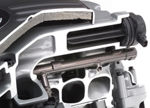 figure 12
 |
figure
13 |
figure
14 |
figure
15 |
figure
16 |
figure
17 |
figure
18 |
|
return
to Table of Contents |
|
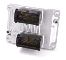
| Electric
Power Steering Diagnosis |
This
additional information pertains to the Electric Power Steering (EPS)
on the 2004 Chevrolet Malibu (see details in the September 2003 TechLink).
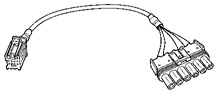
The power steering motor and power steering control module (PSCM) are
serviced as an assembly, separate from the steering column. This results
in the need for a test harness EL-47564 (fig.
19) for certain diagnostic procedures, to determine if the PSCM
is or is not the cause of the malfunction.
If you are faced with a DTC C0545 (steering shaft torque sensor) or
a DTC C0460 (steering wheel position sensor), you will need to use the
PSCM test harness when using either of the diagnostic tables. Refer
to the appropriate section of SI for details.
Follow this path: > build vehicle > Steering > Power Steering
System > Diagnostic Information and Procedures > DTC.
To perform the diagnosis, disconnect the torque/position sensor harness
connector from the PSCM (fig 20). Connect
PSCM the test harness. Then, using a 3 amp fused jumper wire, perform
the tests listed in the SI procedure, while observing the results on
your Tech 2.
- Thanks to Scott Bower |
figure
19 |
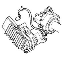
figure 20 |
| return
to Table of Contents |
|
| Exterior
Lamp Condensation |
Moisture
inside exterior lamps continues to be a concern. Bulletin 01-08-42-001A,
released in November, defines the causes, and provides guidelines for
determining the difference between condensation and a lamp with a water
leak.
Refer to the bulletin for details. Here are some of the highlights.
Condensation -- Condensation (fog) inside the lamp
housing occurs after a period of high humidity, which is an atmospheric
condition. The condensation should clear when the vehicle is parked
in a dry environment or when driven with the lights on. If condensation
occurs, replacing the lamp assembly may not correct the condition.
Leak -- Drops of various sizes collecting on the inside
of the lens after being exposed to rain or a car wash indicate a leak.
Water accumulated from a leak won’t clear if the vehicle is parked
in a dry environment, or when driven with the lights on. Water accumulation
in the lamp assembly indicates a need for service.
-
Thanks to Gary McAdam |
|
|
|
return
to Table of Contents |
|
| Fuel
Line Quick Connectors |
Two new style fuel line quick connects are in use.
The TI Group Global Quick Connector is used on C/K trucks, S/T trucks,
Malibu Sedan, Cadillac XLR and the 2004.5 and 2005 Chevrolet Corvette.
The Legris QC is used on Aztek, Rendezvous, Venture, Montana and Silhouette.
Release
Both Types -- To release the quick connect, push on the retainer using
hand pressure only. Do not attempt to remove it. (fig.
21)
A - TI type
B - Legris type
Do not use sharp or pointed objects to put pressure on the connector
retainer. Using a tool may fracture the retainer, making it less effective
at keeping the connector assembled. Also, attempts to remove the retainer
with the line inserted will result in retainer breakage.
TIP: If the connector
does not release with hand pressure, thoroughly clean it and blow out
grit and dirt with compressed air.
Repair
TI Group Global -- If the retainer is broken, it is
not necessary to replace the entire fuel line and attached component
to repair it. Three sizes of replacement retainers are available (fig.
22).
5/16
po |
21992748 |
3/8
po |
22717568 |
5/8
p0 |
21992746 |
Legris
-- Replacement parts are not available for the retainer.
- Thanks to Dave MacGillis |
figure
21 |
| |
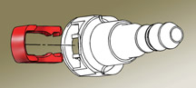
figure 22 |
|
return
to Table of Contents |
|
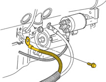
| No
Crank, No Start |
If
the owner of a 2004 LeSabre or Park Avenue/Ultra built before December
19, 2003 experiences a no crank, no start condition, check the negative
battery cable torque at the engine block. The negative battery cable
may be loose or not torqued to specification (fig.
23). The ground location (G101) may not be drilled or tapped
deep enough into the engine block to allow the bolt to achieve the recommended
torque.
To correct this concern, install a shorter bolt or add two star washers
to reduce the height of the bolt.
- Thanks to Bill Metoyer
original
bolt |
12556062 |
shorter
bolt |
11517862 |
|
figure
23 |
|
return
to Table of Contents |
|
| Quality
Service Experience “How-To” |
Customers
who take delivery of a new vehicle during November and December are
eligible to receive a J.D. Power Initial Quality Survey 90 days later.
Because the surveys won't reach the customer until February through
April, the customer may have the opportunity to return to the dealership
for service before receiving their survey. The customer's service experience
can positively, or negatively, affect their perception of vehicle quality,
so the service department team has the opportunity to influence J.D.
Power scores.
It's essential that the customer be provided with an outstanding service
experience that exceeds their expectations. This includes:
Providing hassle-free service -- Make it easy for customers
to do business with you. Do you offer extended service hours? Are you
open on Saturdays?
Fixing vehicles right the first time -- Use
technical service bulletins and Service Information (SI) to identify
the correct repair. Pay special attention to the Field Product Reminder
- Car and Truck Fix it Right the First Time Issues, Parts Restriction
Information and Bulletin Summary bulletin, which is published once a
month.
Helping customers understand how vehicle features and controls
work -- Handle these issues right on the service drive
by using the Getting to Know Your Vehicle guides. Are your service advisors
trained on new product features, so they can answer customers' questions?
Making each service visit a "non-event" by exceeding customer
expectations -- An outstanding service experience may
more than compensate for the original repair issue. You want your customers
to leave your service department feeling completely satisfied.
Following-up with customers 2 to 3 days after service
-- Make sure customers are completely satisfied and understand the repairs
that were performed.
Dealer personnel are the last to touch the vehicle and to interact with
the customer before they receive a J.D. Power survey, the final link
in the quality chain.
- Thanks to Diana Sancya |
|
|
| return
to Table of Contents |
|
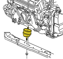
| DeVille
Engine Mount Replacement |
On
the 2000-04 Cadillac DeVille, modifications to the front engine mount
have resulted in the following changes:
- Front engine mount serviceable as a separate part, without bracket (fig.
24)
- Revision of replacement procedure. In SI, refer to Engine Mount Replacement
- Front in Engine Mechanical, or document 447931 (MY 2000) or 714354 (MY
2001-04).
- Revision of labor time
Refer to bulletin 03-06-01-029 for complete procedure and details.
-
Thanks to Bill Denton |
figure
24 |
|
return
to Table of Contents |
|
2004
Cavalier Accessory Power Outlets |
Many
Cavaliers were susceptible to blowing the cigar lighter fuse when certain
power accessory plugs were used in the outlet. For production, Engineering
has switched from a cigar lighter housing to an Accessory Power Outlet
(APO) on the instrument panel.
Cigar lighters and APOs use different electrical connectors. During
the time while the electrial harness was being redesigned, Engineering
created a hybrid APO. It consists of the body of a standard APO and
the connector base of a cigar lighter housing (fig.
25).
A Standard cigar lighter base
B Standard APO body
C Hybrid APO
10,500 Cavaliers were built with the hybrid APO (between VIN breakpoints
1G1JC52F947205493 and 232627). After the end breakpoint, the I/P wire
harness will be using a universal connector that allows either the APO
or the cigar lighter housing to be used.
TIP: They hybrid
part will not be available to service. Use only the cigar lighter housing
to replace the hybrid..
-
Thanks to Bill Denton |
figure
25 |
| return
to Table of Contents |
|
| Tail
Lamp Circuit Board |
Bulletin
03-08-42-006A presents information about the circuit board used in tail
lamps of 2002-04 TrailBlazer, Envoy and Bravada, and 2004 Ranier (fig.
26).
A new circuit board is available for repair if diagnosis leads to a
failed tail lamp bulb. If the lamp is loose, or the board is failed,
install a new circuit board on both sides.
TIP: The preferred
bulb is now supplied by Sylvania. Previously, the bulb may have been
provided by various suppliers.
-
Thanks to Bill Denton |
|
figure
26 |
| return
to Table of Contents |
|
| SSR Correction |
An
article on page 4 of the December 2003 TechLink contained outdated information
about the Chevrolet SSR. The corrected information is shown in bold.
Remote Keyless Entry
The Tech 2 must be used for this procedure. When “building”
the vehicle, specify 2003 or 2004 SSR. Then follow SI
procedures to complete the process.
-
Thanks to Bill Denton |
| |
| return
to Table of Contents |
|
 Car Issues – Fix It Right The First Time (new issues in bold)
 |
Model
Year(s) |
Vehicle
Line(s) --
Condition |
Do
This |
Don’t
Do This |
Reference
Information / Bulletin |
2000-2004 |
Cavalier/Sunfire
- Grinding noise when clutch pedal fully depressed. |
Replace
clutch hydraulic line |
Don’t
replace Clutch/Bearing |
03-07-31-005
Dated 10/30/03 |
1997-2004 |
Grand
Am/Alero/Malibu – Brake pulsation |
Turn
rotor and use brake align procedure |
Don’t
replace rotors for pulsation |
00-05-23-002
01-05-23-001 Know How 15040.01B |
2003 |
DeVille
– No Crank/No Start |
Inspect
base of UBEC to ensure wire connectors fully seated, not loose |
Don’t
replace PCM |
03-06-03-009 |
2004 |
Grand
Prix -- Steering, suspension or cradle click noise. |
Re-torque
right steering gear mount |
Don’t
replace steering gear |
03-02-32-048
Dated 10/28/03 |
2000-2004 |
Buick
Century and Regal
-- CJ3 Manual Dual Zone HVAC fan/mode control knob failures |
Fan
and mode knobs are serviceable |
Don’t
replace CJ3 HVAC control head for failed knob |
VSSM
BB –12/15/03
Dealer VME 12/15/03
Dealer Bulletin Requested |
2000-2004 |
IXLR,
Impala/Monte Carlo, Grand Prix -- Headlamp Replacement for Condensation
in Lamp |
Normal
condition when limited to fog or fine mist appearance in high
humidity conditions |
Don’t
replace headlamp assembly when no water droplets are evident or
condensation covers less than 50% of lens |
01-08-42-001A
11/4/03
Sept 2002 TechLink |
2003-2004 |
CTS
– Variable Effort Steering (VES) “Service Steering
Message” DTC C1241 or C0450 |
Replace
VES solenoid only |
Don’t
replace entire steering gear |
03-02-36-001 |
2003 |
All
cars with 4T40/45E, 4T65E and 4T80E – Code P0742 |
Replace
TCC PWM
Solenoid |
Don’t
replace transmission or valve body assembly |
02-07-30-039B
(Part #’s in bulletin have been superceded) |
2002-2004 |
All
cars with 4T40/45E and 4T65E -- DTC P0716, P0717 and other misc
codes |
Disconnect,
inspect, and reconnect transaxle wiring harness at transaxle |
Don’t
replace input speed sensor |
02-07-30-022B
(10/03)
Sept 2003 Techlink
12/03 IDL |
200-2004 |
NorthStar
Crank Sensors -- during limited parts availability period. |
Replace
only sensor that is diagnosised as faulty |
Don’t replace both sensors for insurance |
Dealer
VME Sent 10/03 and 12/03 |
|
| return
to Table of Contents |
|
|
 Truck Issues – Fix It Right The First Time (new issues in bold)
|
Model
Year(s) |
Vehicle
Line(s) --
Condition |
Do
This |
Don’t
Do This |
Reference
Information / Bulletin |
2002-2004 |
Fullsize and Midsize Pickups and Utilities – Transfer Case |
Use
Labor Operation K9993 whenever transfer case issue cannot be duplicated
or resolved after diagnostic efforts. |
Don’t
use Labor Operation K9992 (for manual trans) or Labor Operation
K9995 (for automatic trans) |
Service
VME
VSSM20030117 |
1999-2003 |
Fullsize Pickups – Rear Leaf Spring Slap Noise |
Replace
inserts and rubber washers |
Don’t
replace leaf spring |
03-03-09-002 |
2002-2004 |
TrailBlazer, Envoy, Bravada, Rainier with HomeLink Universal Transmitter
– Programming Diagnosis |
Use
J-41540 – GM Integrated HomeLink Tester (essential tool).
Follow SI and refer to customers to their Owner’s Manual. |
Don’t
replace HomeLink Transceiver without validating internal fault
recognized by J-41540 |
01-08-97-001B |
2002-2003 |
TrailBlazer,
Envoy, Bravada – Squeak/Rub/Scrub Type Noise in Steering
Column |
Lubricate
and remove material, per bulletin |
Don’t
replace upper or lower intermediate shaft |
02-02-35-006A |
2002-2004 |
TrailBlazer, Envoy, Envoy XL, Bravada, Rainier – Tail Lamp
Socket Circuit Board |
Replace
both tail lamp circuit boards |
Don’t
replace complete tail lamp assembly |
Service
VME, 9/22/03
03-08-42-006A |
2003-2004 |
Fullsize
Pickups and Utilities – Servicing Wide Load Mirrors (RPO
DPF) |
Replace
individual parts as needed |
Don’t
replace complete mirror assembly |
03-08-64-028 |
2003 |
Fullsize
Pickups and Utilities – Transfer Case Service Light/New
Venture Gear Transfer Case |
Verify
that encoder motor is primary cause. Replace encoder motor sensor
and reprogram TCCM |
Don’t
replace module, encoder motor or transfer case for DTCs C0327,
P0836, P0500 |
03-04-21-001B |
2003 |
Fullsize
Pickups – 6.6L Diesel Engine ECM |
Follow
SI and bulletins for proper diagnostics for P0181. Refer to the
Owner’s Manual (block heater and front cover) |
Don’t
replace ECM (DTCs P0540 and P0181) unless diagnostics confirm
need to replace |
02-06-04-048,
03-06-04-021, 02-06-04-058 |
2002-2004 |
TrailBlazer,
TrailBlazer EXT – Wavy Front Fascia |
Repair
fascia with Dual Lock |
Don’t
replace front fascia |
02-08-62-004 |
2002-2004 |
TrailBlazer,
Envoy, Bravada – Mirror Erratic Return |
Replace
mirror actuator and reprogram module |
Don’t
replace outside mirror assembly |
02-08-64-008
02-08-64-021 |
|
| return
to Table of Contents |
|
|
| Know-How
Broadcasts for March |
| |
 |
| Know-How
Broadcasts for March |
| |
|
NOTE
TIME CHANGE |
| 10280.03D
Emerging Issues |
March
11,
2004 |
9:00
AM, 12:30 PM,
3:00 PM
Eastern Time |
| 10280.15D
Envoy XUV Water Management |
March
25,
2004 |
9:00
AM, 12:30 PM,
3:00 PM
Eastern Time |
| -
Thanks to Tracy Timmerman |
|
|
| return
to Table of Contents |
|
