| |
| |
Note: Click a picture or illustration in the left column to view a large version in the article.
To hide the large version, simply click on it.
|
|
Solstice Rear Caster |
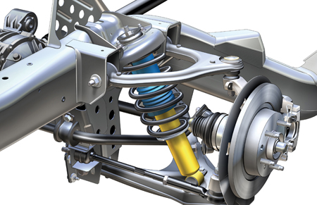
The Pontiac Solstice enjoys the distinction of being the first GM vehicle to have adjustable rear caster (fig. 1). It will soon be joined by the Saturn SKY.
A procedure has been developed to measure rear wheel caster, using a new Digital Angle Gauge. But first, a little detail on rear caster.
Rear Caster
Rear caster adjustment is used on the Solstice and SKY to insure rear ride steer (bump steer) is within specification. Ride steer is toe change during vertical wheel travel.
On a front suspension, it’s common to check caster by doing a “caster sweep,” in which the wheels are steered through an angle, and the caster angle is indicated. Because the rear wheels don’t have steering gear, a caster sweep is not possible. So a direct measurement is necessary.
Digital Angle Gauge
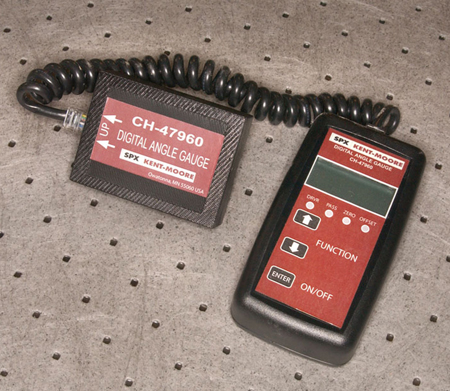
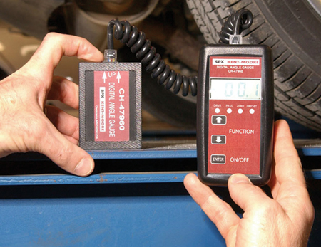
A new Digital Angle Gauge CH-47960 (fig. 2) has been released by SPX Kent-Moore. It will be essential for all Pontiac and Saturn dealers.
Instructions for use are supplied with the gauge. Here are some highlights.
The gauge consists of three parts: a battery powered control unit, a sensor, and a connecting cable.
The control unit provides simple input buttons:
- to specify the side of the vehicle being checked (driver or passenger)
- to zero the instrument.
- to specify offset
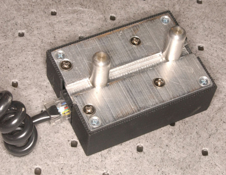
There are two locating pins on the back of the sensor (fig. 3). They can be adjusted up and down by twisting to loosen and tighten.
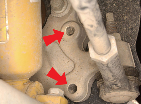
The pins are inserted into two manufacturing gauge holes in the rear wheel knuckle (fig. 4).
Measuring Tips
Before using the gauge, it must be zeroed to the alignment rack (fig. 5). This is accomplished simply by placing the sensor on the rack and pressing the zero button. Zeroing accounts for variations in the levelness of individual alignment racks, so it’s never a concern. You don’t have to do any math or make allowances.
TIP: Be sure both the bottom of the sensor and the surface of the alignment rack are free of debris, to avoid an inaccurate zero.
Before installing the sensor to the knuckle, use a soft (nylon) bristle brush to clean debris from the gauge holes. Do not use power tools or abrasives.
Use the appropriate pushbutton on the control unit to indicate which side of the vehicle you’re working on, either driver or passenger.
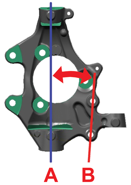
A vertical line drawn through the gauge holes in the knuckle (B) is not quite perpendicular to the axis between the two balljoints (A). So you need to locate the specification of that angle and input it into the tool. This is called the offset (fig. 6), and in the case of the Solstice rear wheels, it’s +3.7°.
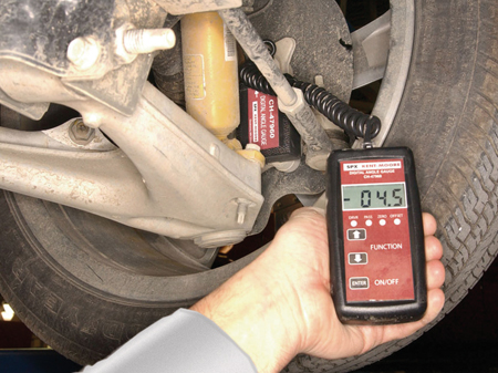
Finally, take the caster reading (the specification is -4° +/- 0.5°). By specifying the offset angle earlier, you set up the gauge so the readout indicates the actual caster angle (fig. 7). You don’t have to do any math.
TIP: If you study the front and rear suspension of the Solstice, you may notice that the driver front knuckle resembles the passenger rear knuckle, and the passenger front and driver rear knuckles resemble each other. This suggests that you could use the gauge to check front caster. This would require inputting “driver” into the Digital Angle Gauge when working on the passenger side, and vice versa. Don’t be tempted to do this, however, because the front offset angle is different from the rear, and this specification has not been published.
Alignment Tips
TIP: It’s important to complete the rear wheel alignment before aligning the front end.
IMPORTANT: If you do not have Digital Angle Gauge CH-47960, do not attempt to adjust rear caster. In this case, set only rear camber.
TIP: When you do a rear wheel alignment, you will observe adjustments for camber and toe from your alignment rack readout, and caster from your Digital Angle Tool.
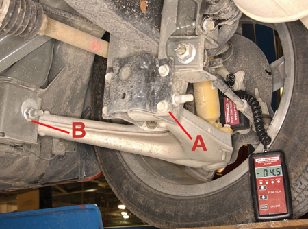
There are two adjustment cams on the rear lower control arm (fig. 8). The front cam is used to adjust caster, and the rear cam is used to adjust camber. Toe is controlled by an adjustable rear toe link.
A Rear cam -- camber
B Front cam -- caster
It’s important to make the suspension checks and adjustments in the following order, to minimize having to make multiple passes.
1. Camber
2. Caster
3. Toe
4. Fine tune camber *
5. Fine tune caster *
6. Fine tune toe*
* if required
TIP: Both cams affect caster to some extent, but the rear cam affects camber about eight times as much as it affects caster. This is why you should set camber first, then caster.
These procedures are being prepared for addition to SI.
- Thanks to Dan Stress and Steve Padilla
- Photos by Chuck Cloud
|
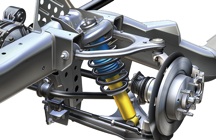
figure 1 |
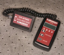
figure 2 |
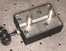
figure 3 |
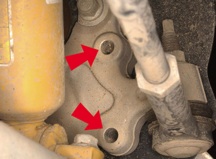
figure 4 |
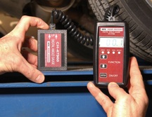
figure 5 |
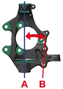
figure 6 |
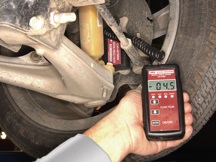
figure 7 |
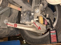
figure 8 |
return
to Table of Contents |
|
|
| Stored Snapshots |
You have several choices of equipment to record a snapshot of vehicle data -- either your Tech 2 or your Vehicle Data Recorder (TechLink, Dec. 2003). After recording the snapshot, it’s usually necessary to download it to your Techline PC terminal for further use and analysis.
There may be a need for you to find where the snapshot file is located on your PC’s hard drive. Here’s how to locate the snapshot file.
Locating Snapshot on Your PC’s Hard Drive
For Tech 2 snapshot location/files, follow this path:
My Computer
C: drive
Program Files
Cosids
Data
SNAPSHOT
Snapshot files “.sur” or “.txt”
For VDR snapshot location/files, follow this path:
My Computer
C: drive
Program Files
GM
VDR Host Application
Snapshot files “.vdr”
TIP: Snapshot files are automatically named when they are downloaded to the PC. You must use the time and date to identify the file.
Renaming the Snapshot File
It is usually not necessary to rename a snapshot file. But if you do so, be sure NOT to change the dot or the extension (the letters after the dot).
Moving the Snapshot File
You may need to move the snapshot file to another computer. One reason may be to email it to Technical Assistance. If the PC in your service bay doesn’t have email capability, you’ll need to move the file to a PC that has internet connection.
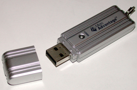
Many of today’s computers no longer provide a “floppy disc” drive. In this case, the preferred method is to use a USB flash drive (fig. 9), also known as a “thumb drive.” (So-called because it’s about the size of your thumb.)
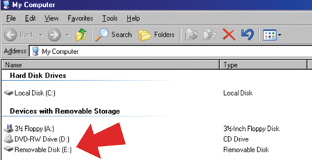
When the flash drive is plugged into the USB port on your PC, it is recognized in My Computer as a Device with Removable Storage. In the photo, it’s Removable Disk E (fig. 10).
Then simply drag the file from your hard drive onto the flash drive, carry the flash drive to the other computer, and drag the file onto its hard drive. You can now attach the file to your email.
- Thanks to Mark Stesney and Jack McVoy
|
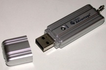
figure 9 |
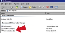
figure 10 |
| return
to Table of Contents |
|
| Quality Service Experience “How-To” |
Customers that take delivery of a new vehicle during November, December and January are eligible to receive a J.D. Power Vehicle Quality Study survey 90 days later. The surveys reach the customer between February and April. So, the customer may have the opportunity to return to the dealership for service before receiving their survey. The customer's service experience can positively, or negatively, affect their perception of vehicle quality, so the service department team has the opportunity to influence J.D. Power scores.
The J.D. Power Vehicle Quality Study survey has been redesigned for 2006. The new survey will have more information for problem-solvers and will better distinguish between design issues and actual defects. However, it will also increase the number and type of problems that customers have the opportunity to report. So it's essential that the customer be provided with an outstanding service experience that exceeds their expectations. This includes:
Providing hassle-free service -- Make it easy for customers to do business with you. Do you offer extended service hours? Are you open on Saturdays?
Fixing vehicles right the first time --Technical information is now updated daily on the web, so the latest information is always available in SI (Service Information). Use this information to identify the correct repair and to help you fix it right the first time.
Helping customers understand how vehicle features and controls work -- Handle vehicle feature issues right on the service drive by using the Getting to Know Your Vehicle guides (Customer Convenience/Personalization Guide -- Cadillac, and In-Vehicle Safety & Quick Reference Guide -- Saab). There’s a significant increase in the number of questions on features, controls, navigation systems, and entertainment systems on the new J. D. Power survey. Are your service advisors and technicians trained on new product features, so they can answer customers' questions?
Making each service visit a "non-event" by exceeding customer expectations -- An outstanding service experience may more than compensate for the original repair issue. Take the time to explain exactly what was done to repair the vehicle.
Following-up with customers 2 to 3 days after service -- Make sure customers are completely satisfied and have no other issues.
Dealer personnel are the last to touch the vehicle and to interact with the customer before they receive a J.D. Power survey, the final link in the quality chain.
- Thanks to Diana Sancya |
| |
|
return to
Table of Contents |
|
Torque Converter Replacement |
Bulletin 01-07-30-010A was just released to provide information on how to determine whether a torque converter should be replaced. This information applies to all GM cars and trucks with automatic transmission (except equipped with VTi).
An analysis of torque converters that have been replaced shows that a high percentage are determined to be No Trouble Found.
Do Not Replace
The bulletin includes 5 conditions under which the torque converter SHOULD NOT BE replaced.
These include DTC P0742 (TCC stuck on), fluid has an odor or discoloration, fine metal particles in the fluid (traces of metal flakes/gray color to fluid), high mileage, and small amount of wear on the hub where the oil pump drive gear mates to the converter.
Replace
In addition, the bulletin includes 13 conditions under which the torque converter SHOULD BE replaced.
These include TCC shudder and/or no TCC apply, damaged oil pump assembly and other specified parts, metal chips/debris in the converter, external leaks in specified weld areas, issues with the converter pilot or converter hub, contaminated transmission oil, excessive end play, metal chips/debris in the fluid filter but internal parts not worn or damaged, unbalanced converter, blue converter or dark circular ring between lugs, converter bearing noise in Drive or Reverse at idle but not in Neutral and Park, and viscous clutch silicon in the lower pan (4T80-E ONLY).
The descriptions given here are highlights only. Refer to bulletin 01-07-30-010A for complete details.
- Thanks to Bill Metoyer |
return
to Table of Contents |
|
| Fuel Economy Improvement Schemes
|
Various schemes to improve vehicle fuel economy have been reported for decades, ranging from magnets that align molecules to chemical combustion improvers. At times when gasoline prices are high, the driving public’s desire is intensified to wring the most miles out of each gallon of fuel. Unfortunately, during such times the public also tends to believe claims more readily than it otherwise would.
Most products claiming to provide benefits are based on anecdotal evidence. Those that do present “scientific” results either have too few data points to be conclusive, have not conducted experiments in a controlled fashion, or cannot be substantiated by anyone else.
The U.S. Federal Trade Commission summarizes results for products tested by the federal government at www.ftc.gov/bcp/conline/pubs/autos/gasave.htm. A review of the list shows that the majority did not work, and for those that showed some effect, the benefit was too small to be cost effective.
One recent idea to improve fuel economy that should not be attempted is blending either kerosene or diesel fuel into gasoline. Why? Both kerosene and diesel fuel are distillate fuels meant for use in compression ignition engines, not spark ignition engines. They have very low octane and, because they are heavier (higher density) than gasoline, they will cause heavy engine deposits and degradation of engine oil.
Chemicals that are normally used as solvents also should not be used. These include acetone, ketones, and methanol. These solvents can be incompatible with elastomers used in vehicle components and can dissolve the vehicle’s paint finish. In the case of methanol, corrosion of metal parts in the fuel system also will occur.
Simple things that can be done to get the most out of every gallon of fuel are:
- Buy only the octane grade recommended for the vehicle. Buying a higher octane grade is wasting money.
- To help keep fuel injectors and intake valves clean, buy gasoline advertised as TOP TIER Detergent Gasoline. Clean engines help provide optimal fuel economy and performance and reduced emissions.
TIP: When TOP TIER fuels are not available, consider a bottle of GM Fuel System Treatment PLUS p/n 88861011 (88861012 in Canada) at oil change time.
- Thanks to Jay Dankovich |
return
to Table of Contents
|
|
GM Fuel System Treatment PLUS |
Beginning in October 2005, GMSPO is filling orders for GM Fuel System Treatment PLUS p/n 88861011 (88861012 in Canada).
The PLUS portion of GM Fuel System Treatment is the addition of a “filmer” additive that, when used regularly, can protect fuel sending units from the corrosive effects of sulfur contaminants found in some of today’s gasoline.
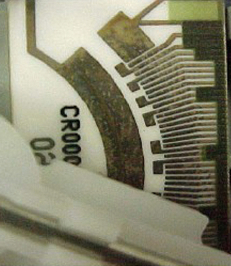
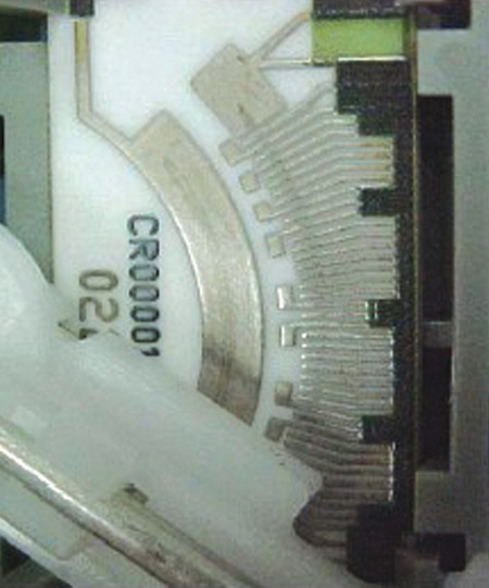
Sulfur contamination may disrupt electrical continuity of fuel sending units and lead to erratic or false fuel gauge readings (fig. 11). When used regularly, GM Fuel System Treatment PLUS provides protection against the effects of harmful sulfurs in gasoline (fig. 12).
One bottle of GM Fuel System Treatment PLUS added to the fuel tank at each oil change:
Cleans: sulfur corrosion from fuel gauge sending units.
Prevents: harmful sulfur components from attacking sensitive fuel system electronics.
Protects: by coating metallic surfaces of the fuel system.
Removes: engine deposits left from use of poor quality fuels.
TIP: Fuel System Treatment PLUS replaces GM Fuel System Treatment p/n 12345104 (89020804 in Canada).
- Thanks to Jay Dankovich |
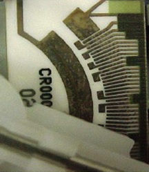 figure 11
 |
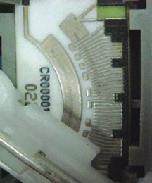 figure 12
 |
|
return to Table of
Contents |
|
| Radio Volume |
The 2006 Pontiac Torrent and Chevrolet Equinox have an optional Premium Sound System that includes an amplifier. The service radios are configured to have "no amp present" as the default setting. If one of these is installed in a vehicle that does have an amp, the volume will be too loud and too sensitive to changes.
A test is available in the Tech 2 called Radio Setup, which prompts the user to determine if the vehicle is equipped with an amplifier. These are the paths to the test.
For Torrent: Diagnostics > (6) 2006 > LD Trk, MPV, Incomplete > (M) Pontiac APV > L >> Body >> Radio > Special Functions > Radio Setup
For Equinox: Diagnostics >> (6) 2006 >> LD Trk, MPV, Incomplete >> (C) Chevrolet Truck >> L >> Radio >> Special Functions >> Radio Setup
A VIN Relearn still needs to be performed in addition to the Radio Setup test.
This test will be released to dealers on CD 11.
- Thanks to Brian Buck
|
| |
| return
to Table of Contents |
|
|
Avoiding PCM Connector Damage |
Connectors on some Powertrain Control Modules (PCM) are retained by bolts, and others by assist levers, using slides.
The SI procedure for PCM removal includes this statement:
“Remove any debris from around the PCM connector surfaces before servicing the PCM.”
It’s important to observe this step on all PCMs, to prevent contamination from getting into the PCM header when the connector seal is opened.
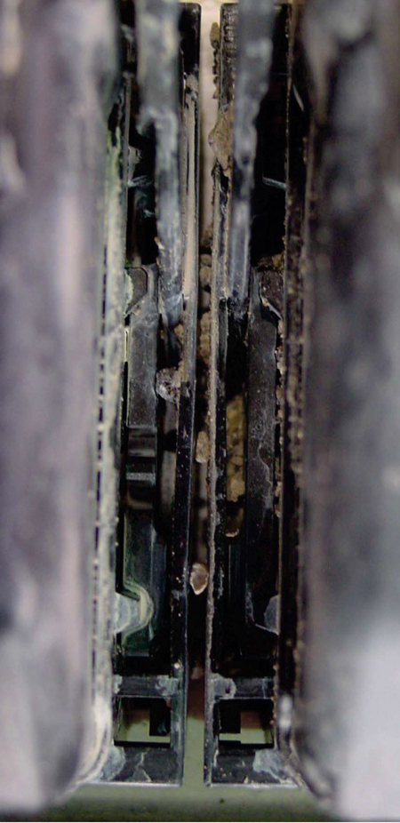
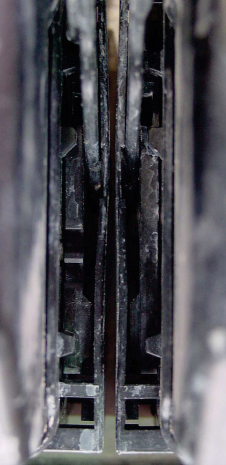
But, it’s extra important on PCMs that use assist levers for connector retention. The slides must be pushed or pulled to unlatch or latch the connectors. If there is a buildup of dirt in the slide troughs the assist lever may be broken when you attempt to move it.
(fig. 13) Dirty
(fig. 14) Clean
And when you reconnect the harness, be sure that the gaskets are installed correctly. The gaskets prevent contaminant intrusion into the PCM.
- Thanks to Jack Woodward
|
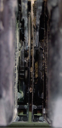
figure 13
|
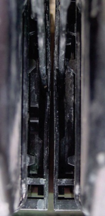 figure 14
 |
| return
to Table of Contents |
|
| Electro-Viscous Fan Clutch Characteristics |
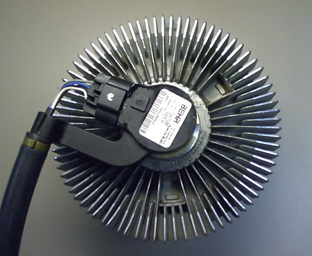
2002-06 GMT midsize utilities with either I6 or V8 engines are equipped with an electro-viscous (EV) fan clutch (fig. 15). Specific operating characteristics and diagnostic information are available in SI and on the Tech 2. For example, the Tech 2 has a data list that shows requested and actual EV fan clutch speeds (except for 2006 4.2L LL8 inline engines).
The requested fan speed can be much higher than what is shown for actual fan speed. If this is misunderstood, it can lead to replacement of the fan clutch when in fact it is operating as intended.
The requested fan speed is the highest desired output from multiple parameters within the PCM (such as engine coolant temperature, A/C pressure, transmission temperature). The highest parameter however may not be the ruling parameter, and the requested fan speed display can be significantly higher than the actual fan speed display.
Depending on the model, the EV fan speed can be manually controlled with the Tech 2 in the Powertrain Special Functions section. It is possible in this mode to set the requested fan speed higher than the vehicle is capable of producing. For example, 2000 rpm can be manually requested while the engine is at 1000 rpm, and 2000 rpm will not be set until engine speed is increased.
TIP: For 2006 vehicles with the 4.2L LL8 engine, the desired and requested fan speed data has been removed from the Tech 2. Diagnostic information is being updated to reflect this change.
Additionally, as explained in SI, the fan clutch is by nature slow to respond to Tech 2 commands or a fused jumper wire test as listed in SI (see document 1480802 for an example). If the SI diagnostics are not followed properly, it can lead to unnecessary EV clutch replacements.
The only time the EV fan should be replaced is when specific conditions are identified by following the proper diagnostics in SI or in Technical Service Bulletins. For example: Intermittent Slow to Cool HVAC Performance Concerns in High Ambient Temperatures and/or High Humidity Conditions After Start Up, Especially at Low Engine Speeds (Install New Engine Cooling Fan Clutch) 04-01-38-019A, which DOES NOT APPLY to 2006 vehicles.
Finally, the changes to the EV fan clutch to improve HVAC performance will increase airflow in certain conditions. It is possible during startup for the EV fan clutch to be engaged (depending on check valve orientation) and the EV fan may match engine speed for about 1 minute, depending on driving speeds. Lower speeds will have a longer engagement time.
If the engine is shut off off after a high cooling load drive cycle (EV full on), the restart will occur with the fan making noise, which some customers interpret as low engine power and/or transmission slipping.
Vehicles parked nose-up on an incline 16% or greater (such as vehicles coming off transport, or parked on a steep driveway) can have an extended amount of fan noise. Once the vehicle is not parked under these conditions, the fan should operate as described. DO NOT replace EV fan clutches for these conditions, which are normal. If the fan clutch is truly operating at a speed higher than intended, a DTC P0495 or P1484 should set.
- Thanks to BJ Lackey |
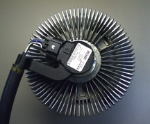 figure 15
 |
| return
to Table of Contents |
|
Crankshaft Seal Replacement |
This information applies to the 60° V6 engine (2.8L, 3.1L, 3.4L, 3.5L, and 3.9L) used in 1986-2006 GM cars and light trucks.
IMPORTANT: This does not apply to 2004-05 Saturn VUE models with 3.5L DOHC V6 Engine (VIN 4 - RPO L66).
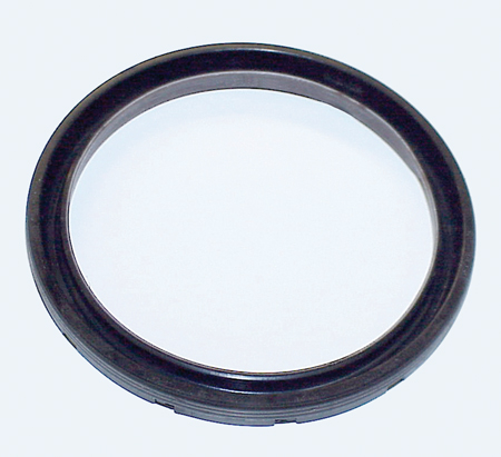
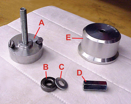
A bulletin 05-06-01-019C is being released explaining a new crankshaft rear main seal (fig. 16) and a revised replacement procedure, using a newly released tool EN-48108.
Part Number |
Description |
12592195 |
Seal Assembly, Crankshaft Rear Main Oil (U.S) |
31022784 |
Seal Kit, Crankshaft Rear Main Oil (Canada) |
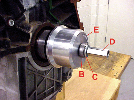
The new tool (fig. 17) allows you to easily install the rear main seal squarely, to the correct depth and in the correct direction.
A. Mandrel
B. Bearing
C. Washer
D. Drive Nut
E. Drive Drum
Refer to the bulletin for step by step details. Here are some highlights.
Removal
Two different procedures are provided, depending on which type of seal is being removed.
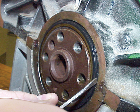
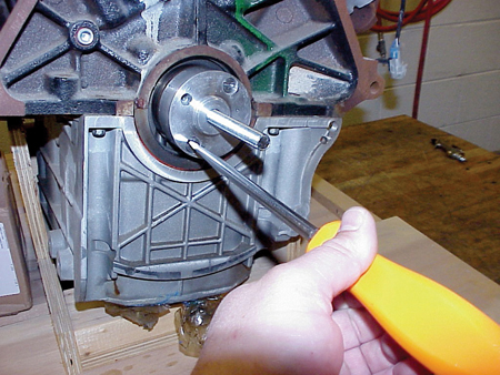
Old style -- The seal lip faces inward. Insert a flat-bladed or similar tool between the outer seal casing and the engine block casting and gently pry the seal out (fig. 18).
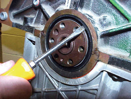
New Style -- The seal lip is faces outward. Insert a flat-bladed or similar tool between the sealing lip and the outer casing of the seal at an angle and pry the seal out by moving the tool toward the center of the crankshaft (fig. 19).
Installation
Before beginning installation, observe these important points in the bulletin:
- Leave the protective sleeve in the seal.
- Do not use lubricants or sealants on the seal.
- Be sure the mating surfaces are clean and free of burrs.
The mandrel is aligned to the end of the crankshaft with a dowel pin (fig. 20) and is retained by two screws (fig. 21).
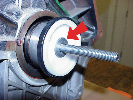
The seal can be installed only one way on the mandrel, and is located on a center step (fig. 22).
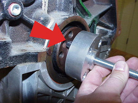
The drive drum, bearing, washer and drive nut install onto the threaded shaft (fig. 23).
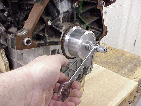
The drum pushes the seal into place, and is stopped when it contacts the engine block (fig. 24).
After installation, remove the tool parts and discard the seal protective sleeve.
Follow bulletin instructions for the completion of the procedure.
- Thanks to Zach Johnson |
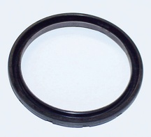
figure 16 |
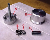
figure 17 |
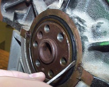
figure 18 |
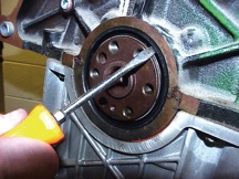
figure 19 |
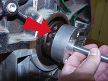
figure 20 |
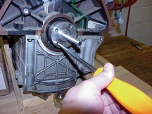
figure 21 |
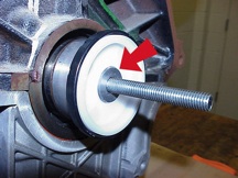
figure 22 |
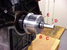
figure 23 |
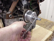
figure 24 |
| return to Table of
Contents |
|
|
Electronic Method to Close TAC Cases Coming Soon! |
You have been asking for an electronic method to close TAC cases and TAC has been listening. Beginning Monday, January 23, 2006 you can access two electronic TAC forms on the DealerWorld Service Tab.
TAC Case Closing Form – Using this form allows you to close TAC cases right after completing the repair, while the repair details are still fresh in your mind. It is further simplified because Labor Operation Numbers are no longer required to close TAC cases.
TAC Case Quality Survey Form – This electronic form allows your service department to rate the quality of the information and service you received from TAC.
Why Closing TAC Cases Electronically is Easier
The new DealerWorld based Case Closing Form takes less time to complete.
- No hand written form
- No faxing the form to TAC
- No calling TAC to leave a case-closing VME.
You can simply select the TAC Case Closing Form on the DealerWorld Service Tab, quickly complete it and submit to TAC for closure. Complete the minimum 4 required fields (previous form had a maximum of 23 fields).
- TAC Case Number
- Last 8 Digits of VIN
- Repair Category
- Repair Information
The following fields are now optional; they are no longer required to close a TAC case:
- Caller name, Dealer name, Dealer Code, etc.
- Labor Op Number
- Full VIN
- Consultant’s name
- RO Number
What is a Quality Case Closing?
TIP: The quality TAC case closing you provide today may help a fellow technician tomorrow. And their case closing may help you next month.
TAC is interested in receiving high-quality, accurate and detailed case closing information. Short and simple is not always the best.
For example, if a left front window is inoperative and the repair was “Replaced the Driver’s Door Module,” a short and clear explanation is fine.
But if the repair was “Repaired Chafed Wire,” this doesn’t tell what was really repaired. A better explanation would be “Repaired brown wire circuit 1232, chafed on park brake pedal bracket.”
Closing the Case on the Call
When the information exchanged during the call does not merit your sending a formal closing, the TAC consultant may close the case at the end of the call.
For example, you are looking for clarification on how a certain feature operates. There is no reason to leave this case open.
Before You Contact TAC
Be prepared when you place the call.
- Vehicle is in the service department
- Condition duplicated or attempted
- Preliminary checks performed (review service history, check for DTCs)
- Review published information (SI, bulletins, system operation, schematics, etc.)
Refer to Bulletin 01-00-89-011B for further details.
TAC Case Log Book
TIP: More information regarding the TAC Case Log Book can be found in the P&P Manual, section 5.3.1.
The TAC Case Log Book helps you reference the case number, and insures closure of the case.
- Input the case information
- Add update information on each call
- Write the closed date next to the TAC case once it has been closed.
You will also be able to print a confirming copy of your TAC case closing right from the DealerWorld website.
There are currently no plans to provide a list of open cases to each service department.
Quality Survey
The TAC Quality Survey Form allows your service department to rate the quality of information and service you received from TAC. You can acknowledge special help from a consultant or suggestions for improvements in real time rather than only when we send you a survey. We will continue to send random surveys to your dealership via DCS.
Transition Period
We will be supporting the Fax and VME based case closing methods until Friday, March 31, 2006. At that time, it is planned that these methods will be discontinued and TAC cases will have to be closed using DealerWorld. We encourage you to use the new process and provide feedback on it.
- Thanks to Mark Gordon, Sarah Pagel and Bill Szelag
|
|
return to Table of
Contents |
|
| Auto Door Locks -- Unable to Disable |
Mode 1 and Mode 2 are the only two programmable lock modes available on 2005-06 Mid-Sized Utilities (Buick Rainier, Chevrolet TrailBlazer and GMC Envoy).
Mode 1: All doors lock when the transmission is shifted out of Park.
Mode 2: All doors lock when the vehicle speed is greater than 8 mph (13 km/h).
Starting in the 2005 model year, it was decided to eliminate Mode 3, "No Automatic Door Locking".
An owner’s manual correction has been submitted for this concern.
- Thanks to Dino Poulos |
|
return to Table of
Contents |
|
| Throttle Position Sensor Circuit |
This information applies to the 2004-05 Chevrolet Aveo and 2005 Pontiac Wave (Canada only) with 1.6L Engine (VIN 6 - RPO L91).
You may encounter a crank-no-start with no injector pulse following engine repairs. Tech 2 data may display 4-5 volts for the TP voltage.
In this case, be sure the AC pressure sensor and TP sensor connectors are not reversed. The TP sensor connector should have a purple circuit, a blue circuit, and a white circuit.
If the connectors are reversed, the TP voltage signal to the ECM will be around 4.5 volts, which indicates wide open throttle. This causes the ECM to activate clear flood mode. In clear flood mode, the ECM turns OFF the fuel injectors completely, as long as the ECM sees a WOT condition while cranking.
- Thanks to Jamie Parkhurst |
| |
| |
| |
| return
to Table of Contents |
|
 Car Issues
— Fix It Right the First Time (new issues in bold) Car Issues
— Fix It Right the First Time (new issues in bold) |
Model Year(s) |
Vehicle Line(s) / Condition |
Do This |
Don’t Do This |
Reference Information/Bulletin |
2005 |
Cobalt, Pursuit (Canada Only), ION, HHR – Transmission Control Module (TCM) Shorted to Battery Voltage During Diagnosis and/or Service |
Remove TCM harness from TCM prior to removing from TCM holding bracket. |
Don’t remove TCM from bracket without first disconnecting TCM wiring harness. Don’t allow TCM to contact positive battery post. |
05-07-30-016A |
2004 |
Grand Prix – Unwanted Intermittent Door Lock Activation |
Reprogram BCM with P/N 15280785. |
Don’t replace BCM. |
05-08-64-016 |
2005 |
VUE, Equinox LT/LS – Sunroof will not Close from Vent, Partly Opened, or Fully Opened Position |
Replace sunroof control module. |
Don’t replace sunroof module, motor or switch. |
05-08-67-010A |
2005-2006 |
Uplander, Terraza, Relay, Montana SV6 – High Effort to Sound Horn, Horn Only Sounds When Certain Spots are Pressed |
Replace horn pad springs. |
Don’t replace inflatable restraint steering wheel module. |
05-08-54-001 |
2005 |
Grand Prix, LaCrosse/Allure – Front Brake Moan and/or Groan Noise During Brake Apply |
Confirm that noise is coming from front brakes – replace front brake pads. |
Don’t resurface front rotors. |
05-05-23-006 |
2004-2005 |
Grand Prix (June built 2004, all 2005), LaCrosse/Allure (all 05) – Blower Motor Inoperative or Intermittent, Blower Speed May Drop or Blower Continues to Run After Key Off |
Install 330MFD capacitor between LPM circuit to ground. |
Don’t replace LPM, blower motor or HVAC control head. |
05-01-39-001A |
2002-2005 |
Buick LeSabre – Front Door Window Binds/Inoperative/Moves Slowly |
Adjust glass. |
Don’t replace window regulator. |
05-08-64-011 |
2002-2007 |
Cavalier, Sunfire, Grand Am, Classic – Vehicle Hesitates, No Start, Lack of Power, Low Fuel Pressure |
Replace fuel pump strainer. |
Don’t replace fuel pump module. |
05-06-04-026A |
2001-2003 |
Aztek, Rendezvous – Window Regulators Separate from Window Motors |
Use window regulator clips and procedure outlined in bulletin. |
Don’t replace window regulator assemblies that are serviceable and only have broken clips. |
03-08-64-015 |
1999-2004 |
All Cars and Trucks – Brake Warranty, Service and Procedures |
Issue One: Refinish brake rotor.
Issue Two: Measure for LRO |
Issue One: Don’t replace brake rotors.
Issue Two: Don’t measure for LRO |
00-05-22-002D |
2002-2005 |
Cars and Trucks – Multiple Driveability Symptoms/Clogged Fuel Injectors |
Clean fuel injectors as described in Bulletin. |
Don’t replace fuel injectors. |
03-06-04-030A |
|
| return
to Table of Contents |
|
|
 Truck Issues — Fix It Right the
First Time (new issues in bold)
Truck Issues — Fix It Right the
First Time (new issues in bold)
|
Model Year(s) |
Vehicle Line(s) / Condition |
Do This |
Don’t Do This |
Reference Information/Bulletin |
2002 |
TrailBlazers, Envoys, Bravada – Essential Tool for HVAC Mode Door Actuator Replacement |
Use GE-47676 to replace HVAC mode door actuator. |
Don’t replace cam assembly. |
05-01-38-001A |
2003-2005 |
SSR – Door Will Not Open From Inside Door Handle |
Replace door handle hinge support. |
Don’t replace door panel. |
05-08-64-026 |
2004-2005 |
Colorado/Canyon – Side Door window Glass Clips Fall Off |
Replace door window glass. |
Don’t re-attach door window glass clips. |
04-08-64-022 |
2001-2005 |
Chevrolet/GMC 36 Series Cab/Chassis – DTC P1172 or P2636, Fuel Gauge Reads Empty, SES Light On |
Modify fuel tank balance line. |
Don’t replace fuel tank unit, PCM or fuel transfer pump. |
05-06-04-008 |
2004-2005 |
All Cars and Trucks – State-of-Charge Upon Delivery of a New Vehicle |
Check battery’s state-of-charge using J-42000 or J-42000-EU. |
Don’t remove and replace battery. |
02-06-03-009A |
2002-2004 |
Silverado, Suburban, Tahoe, Sierra, Yukon/XL, Escalade EXT – Rough Idle, Misfire, MIL DTC P0300 |
Measure intake manifold for warpage across two runner ports only. Replace upper manifold gasket with teal-green gasket. |
Don’t measure intake manifold across all four intake runner ports. Don’t replace upper intake manifold gasket with orange gasket. |
05-06-04-029 |
2001-2003 |
Fullsize Pickups – Injector Replacement for High Flow Rates |
Use Bulletin 04-06-04-007A for injectors with high fuel return rates. Use Special Policy 04039 for all 01-02 vehicles. |
Don’t replace 8 injectors for any complaint other than high fuel return rates. All other injector failures are fix as failed. |
Special Policy 04039 |
|
| return
to Table of Contents |
|
|
|
Know-How Broadcasts for
FEBRUARY |
| |
 |
| Know-How
Broadcasts for FEBRUARY |
|
10206.01D Emerging Issues |
February 9, 2006
9:30 AM and 12:30 PM Eastern Time
|
|
New Model Features |
For Web NMF courses, log on to the GM Training Website www.gmtraining.com. Select Service Know-How/TechAssists from the menu, then choose New Model Features for a selection of courses. |
| -
Thanks to Tracy Rozman |
|
|
return
to Table of Contents |
|