
| Note: Click a picture or illustration in the left column to view a large version in the article. To hide the large version, simply click on it. |


|
||
Power Liftgate Module Programming
|
Some 2007 full-size utilities are equipped with a power-operated liftgate, which opens and closes with the push of a button. The system is controlled by the Power Liftgate Module (PLGM). If you need to reprogram an existing PLGM, or program a replacement, you must perform the following procedure to avoid leaving a current B1019 trouble code which cannot be cleared until the PLGM is “learned.” After completing the programming event, perform the liftgate calibration procedure with Tech 2. TIP: To ensure proper calibration of the liftgate, the liftgate assembly must be at room temperature during calibration. - Close the vehicle liftgate. Failure to do so will result in a failed liftgate calibration. - Connect the Tech 2 to the vehicle. - Select Special Functions in the Liftgate Module menu. - Select LGM Open/Close Test. - Follow the on-screen instructions. TIP: When the liftgate is under control of the Tech 2, the liftgate will be driven to the full open position. An audible sound at this point is normal. Only after following these steps, use your Tech 2 to clear the B1019 code. - Thanks to Devin Koski and Craig Jones |
|
|
||
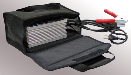
Battery State of Charge figure 9 |
Many service procedures, including the programming of modules, require the ignition key to be turned on, without the engine running. This means that the vehicle’s systems are operating from the vehicle’s battery. For example, the new 2007 full-size utilities have up to 24 control modules, which represent a considerable current draw. To prevent running down the battery below a useable level, take these precautions. - Be sure the battery is fully charged before beginning the procedure. - Consider connecting an approved battery charger during the service procedure. The Midtronics PSC line of chargers (fig. 9) has been validated for use during module programming. Two output levels are available -- the 30 amp PSC-300 and the 55 amp PSC-550. Refer to the July 2005 issue of TechLink for complete information. - Thanks to Mark Stesney |
|
|
||
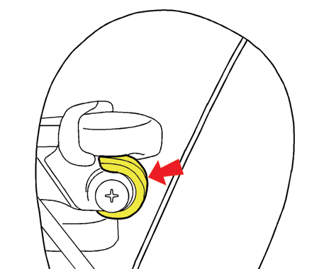
Door Handle Clicking Noise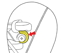 figure 10 |
Some customers may comment that the outside door handle on their 2005-06 Chevrolet SSR makes a clicking noise when opening. Remove the door trim following SI document 1347496. Pull back the water deflector to gain access to the lock cylinder. Apply GM Super Lube p/n 12346241 (10953474 in Canada) to the door handle spring (fig. 10). - Thanks to Dan Oden |
|
|
||
| Temperature Readout |
Owners of some Torrent and Equinox vehicles may experience difficulty switching between Fahrenheit and Celsius output on the rear view mirror temperature display. The operation is not entirely intuitive. With the first press of the TEMP button, the display turns off, and the customer assumes that's not how to make the change. |
|
|
||
Did You Know? |
Module Programming -- The 2006 Cadillac DTS and Buick Lucerne have up to 21 modules that must be reprogrammed or set up with the Tech 2 after replacement. If you are unsure if a module is programmable, check SI. Use the words “Control Module Reference” to search for a table that will identify the modules in your specific vehicle that require programming or Tech 2 set-up procedures. Upgraded Passenger Compartment Air Filter -- The 2006 Buick Lucerne has a Passenger Compartment Air Filter in the HVAC Module. Lucerne owners may purchase an upgraded Carbon Impregnated Passenger Compartment Air Filter that comes standard in the 2006 Cadillac DTS. Look in the Parts Catalog under the 2006 Cadillac DTS for the part number. Valet Key -- The Cadillac DTS has a valet key option as standard equipment. This valet key can also be used on the 2006 Buick Lucerne. Owners may buy this key as a Cadillac service part. - Thanks to Chris Graham |
|
|
||
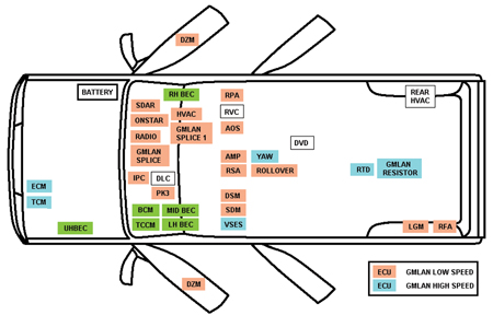
Module Locations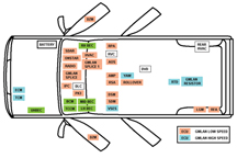 figure 11 |
This illustration shows where control modules are located on the new 2007 full-size utililties (fig. 11).
TIP: At present, this illustration does not appear in SI. Note that the modules on the low speed GMLAN are colored orange, and those on the high speed GMLAN are colored blue. - Thanks to Saundra Massengille |
|
|
||
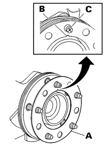
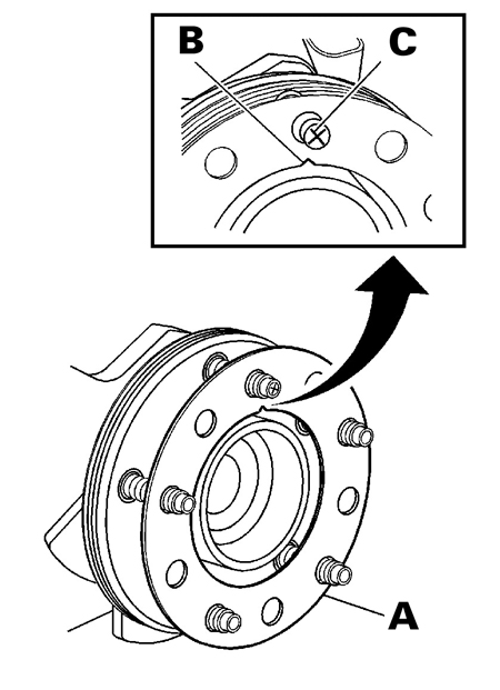
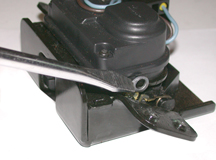
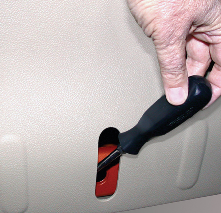
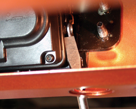
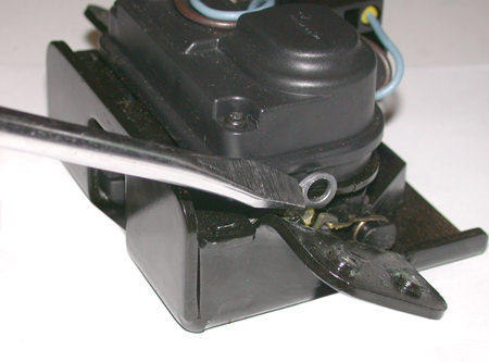
| The liftgate lock on the Chevrolet HHR is operated electrically, either using the remote key fob or the door lock button. Once unlocked, the liftgate can be opened using the liftgate handle. In the case of electrical failure, the lock can be operated manually from inside the vehicle, after a service access plug is removed. TIP: Do NOT attempt to remove the liftgate trim panel when the liftgate is locked shut. Use a small flat-bladed tool to remove the plug from the trim panel (fig.12). Use a light to locate the bellcrank lever, a small metal arm located below and to the left of the access hole (fig. 13). Use a thin, long (6 in, 150 mm) flat bladed tool to slowly push the release lever rearward, until the latch releases (fig. 14). Open the liftgate using the liftgate handle. Refer to SI document 1615300 for more details. - Thanks to Robert Huber and Tom Sklenar |
||


|
|||||||||||||||||||||
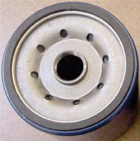
Oil Filter Revision figure 15 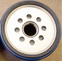 figure 16 |
GM Parts introduced the next generation of Duraguard® oil filters in May 2005. The new locator plate design (flat surface) allows for easier installation in blind applications with no effect to the filter’s performance. A rolling change will begin January 27, 2006, with no part number revisions. The first part numbers to be implemented are the 25011520 (PF53) and 19114118 (PF53F).
- Thanks to Kevin Larson |
||||||||||||||||||||

|
||
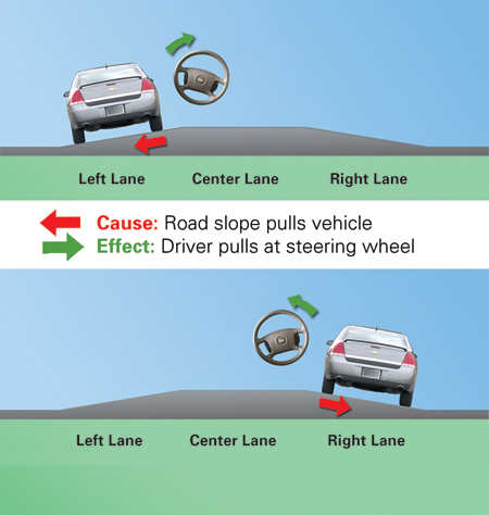
Vehicle Leads/Pulls and Road Slope figure 17 |
When you’re diagnosing a vehicle that leads or pulls, have you considered the effect of road slope? Road slope is a major contributor to vehicle lead/pull complaints. As a part of normal operation, vehicles will follow side-to-side road slope or road crown. So, first check with the customer about the types of roads they are driving on. Some drivers do not recognize the influence of road slope on vehicle pull/lead. Roads typically have some degree of crown or slope to allow for rain run-off. Vehicles are designed to compensate for a slight amount of road crown, but evaluating a vehicle on the wrong roads can lead to improper diagnosis. For example, if you are testing the vehicle for a “leads to the left” concern, you will want to evaluate the concern in the left lane as well as in the other lanes. If the vehicle quickly climbs the road crown, then it may have an issue that needs to be looked into further. So, be sure to understand the customer’s operating environment and whether or not road slope is causing the customer’s concern (fig. 17). RED ARROW: Cause -- road slope pulls vehicle GREEN ARROW: Effect -- driver pulls at steering wheel. TIP: Do your test drive on actual roads, not in a parking lot, to give you a real world impression of the vehicle’s behavior in right and left sloping lanes. For further assistance please reference the leads/pulls diagnosis document in SI. - Thanks to Brian Snyder and Dan Stress |
|
|
||
| Poor Radio Reception |
This information applies to 2001-02 full-size trucks and utilities (both old and new body styles). Some customers may experience poor radio reception. This concern may be related to a loose radio antenna mast. Since April, 2001, an orange or black plastic wrench has been attached to the antenna mast. This tool is provided to properly attach the mast to the antenna base during new vehicle prep. It is then to be placed in the glove box for the owner's use later. TIP: The wrench is made of plastic to avoid damage to the finish on the antenna mast. TIP: Replacement wrenches are available only with new antenna mast assemblies. - Thanks to Paul Radzwilowicz |
|
|
|||||||||||||||||||||
Electric Trailer Brake Controller Wiring |
Owners of the 2007 Cadillac Escalade, Chevrolet Tahoe and GMC Yukon may have questions about how to connect an electric trailer brake controller, or where the brake controller pigtail harness is located.
TIP: The red/black circuit 242 must be connected to Stud 1 (30 amp) of the UBEC. The wire is located between the left fender and the UBEC. Do not confuse this circuit with 742 (document 1706194) which is also red/black, and which is taped to the harness under the master cylinder. Circuit 742 is the 12 V supply to the 7 way trailer connector. - Thanks to Jim Will |
||||||||||||||||||||
|
||
Vehicle Speed Readout on Tech 2 |
This information applies to the 2006 Cadillac STS-V and XLR-V, and Chevrolet Corvette equipped with 6L80 (RPO - MYC). When using a Tech 2 to monitor transmission data, the vehicle speed reading may be higher than the actual speedometer reading. If this condition is found, typically the higher the actual vehicle speed, the higher the Tech 2 reading and the greater the error. This does not cause any driveablility issues and no repair attempts should be made. The issue is being investigated in an attempt to correct the Tech 2 vehicle speed reading in a future calibration release. - Thanks to Rusty Sampsel |
|
|
||
Cruise Control Inoperative |
This information applies to the following vehicles when equipped with manual transmission: 2004-2006 Cadillac CTS-V, Chevrolet Cobalt, Corvette, Silverado and SSR, Pontiac GTO, GMC Sierra, 2006 Pontiac Pursuit and Solstice, and Saturn Ion. The customer may comment that the cruise control inoperative and/or MIL on, and a DTC P0833 is stored. The condition may not be able to be duplicated by the dealer yet the customer may have a repeat concern. Check the clutch pedal top of travel (CCP) switch for adjustment on vehicles where the switch is adjustable. Also check for possible intermittent connections in the clutch switch circuit. In some applications, during circuit testing of the clutch switch (CCP), the Tech 2 may read APPLIED/RELEASE if toggled several times, then stops toggling and remains in either the APPLIED or RELEASED state. If the switch is checked with a DVOM, the switch will toggle from open to closed. TIP: Using a DVOM to check clutch and cruise switches is recommended instead of monitoring Tech 2 data. If no circuit concerns are found, this code can be induced by certain driving habits. This code can set (and the cruise control will be disabled) if the driver rests their foot on the clutch continuously. If the pedal is not permitted to reach the top switch, it will keep the ECM from seeing transitions while the vehicle is driven above and then below the vehicle speeds listed for setting the DTC. This can cause a false P0833 to set. EXAMPLE: Driving in slow moving stop-and-go traffic, such as a construction zone or heavy traffic. Make the customer aware of this scenario and advise them to refrain from resting their foot on the clutch pedal in these situations, to avoid disabling the cruise control and/or setting DTC P0833. - Thanks to Rusty Sampsel |
|
|
||
Rear Axle Pinion Seal Leak |
2003-06 Cadillac CTS 2004-06 Cadillac SRX 2005-06 Cadillac STS 2006 Pontiac Solstice The rear axle pinion seal may exhibit a fluid leak condition. During seal replacement, the new seal may still leak as work on the vehicle is being completed. It is possible that when replacing the seal, the rear axle lube is seeping through the pinion bearings. The lube then gets past the rubber seal and gets trapped behind the metal dust shield before the pinion yoke is installed. When the dealer installs the pinion yoke, the trapped fluid is squeezed out and gives the illusion of a continued leak. TIP: Inspect the new seal for the presence of the internal garter spring and make sure it is there. If not, use a seal that does have it. Inspect the new seal for metal contamination in the grease used to lube the seal lip. If there is any contamination, discard the seal and use only a debris-free seal that is supplied with grease. When replacing the pinion seal, first drain the rear axle fluid. This also helps remove metal contaminants that may be present and may have caused the initial leak condition. Next, remove the leaking seal. Install the new seal and yoke. Last, refill the rear axle. This should prevent the lube from being trapped behind the dust shield. - Thanks to Rusty Sampsel |
|
|
|||||||||||||||||||||||||||||||||||||||||||||||||||||||||||||||||
|
|||||||||||||||||||||||||||||||||||||||||||||||||||||||||||||||||
|

|
||||||||||||||||||||||||||||||||||||||||
|
||||||||||||||||||||||||||||||||||||||||
|
 Truck Issues — Fix It Right the
First Time
Truck Issues — Fix It Right the
First Time
|
|||||||||||
Know-How Broadcasts for April
|
|
||||||||||
|
|||||||||||
