Table
of Contents – May 2003 |
| |
|
|
|
| |
|
|
|
| |
|
|
|
|
|
|
Note:
Clicking on any picture or illustration will open a larger version
of that art.
|
|
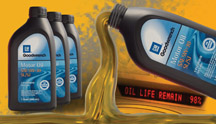
GM
Oil Life System Revisited |
How often should
engine oil be changed?
- 3,000 miles (5000 km)
- 5,000 miles (8000 km)
- 7,500 miles (12000 km)
- 10,000 miles (16000 km)
Actually, all of these are correct, depending on operating conditions. Oil life is affected by many factors other than just miles driven.
The type of driving, temperature, and engine load all play a part.
That’s why GM has developed the GM Oil Life System, an electronic
watchdog that keeps track of all these variables and notifies the driver
when it’s time to change oil. (fig. 1) We first told you about
the GM Oil Life System in the March 2000 TechLink. Since then, the
system has become standard equipment on nearly all GM products.
Briefly, the Oil Life System is programmed with a certain number of
engine revolutions. As the engine runs, this number is reduced until
it reaches zero, and the Oil Life light or message comes on. But there’s
more. Operating the engine under low or high temperatures, and under
high load conditions subtracts (penalizes) extra revolutions, so the
light comes on sooner.
Changing engine oil according to actual need rather than an inflexible
schedule provides several benefits.
First is simpified determination about when to change oil. No more
decisions about “normal” conditions vs. “severe” conditions.
Second is reduced operating costs for GM’s customers, who now
have to change oil only when it’s needed. Third is minimizing
the amount of used oil that must be disposed of. And fourth, engines
will always be running with sufficiently fresh oil, for long life.
These benefits will be realized only if engine oil is actually changed
as indicated by the GM Oil Life System.
Some customers “get it” when it’s explained to them.
Others may be reluctant to deviate from traditional oil change interval
charts. So, part of the responsibility falls on retail service people
to help get the message out.
TIP: To help you do this, an IDL broadcast is being prepared. Consult
the GM Training Program Guide and Schedule for “Understanding
the GM Oil Life System” (PPS03.P1D).
There’s More
Traditionally, the vehicle maintenance schedule has been based on miles
or time, while the oil change interval is now based on the GM Oil Life
System. This could result in customers having to bring their vehicles
in for an oil change when the light comes on, only to find that the
vehicle is due in a month for scheduled maintenance.
That’s all changing. In the accompanying article “Simplified
Maintenance Schedules”, you’ll learn how maintenance intervals
are now being tied into the oil change intervals indicated by the Oil
Life System.
-
Thanks to Jerry Garfield and Chuck Burns |
figure
1 |
|
|
|
|
|
|
| How to Search
on the TechLink Website |
You
can search the TechLink archives, in a roundabout sort of way. Go
to www.google.com and select the advanced search option.
In the blue box, type in the key word(s) you want to search. You can
limit the search four different ways, depending on which box(es) you
type in.
Then in the next section of the form, on the file format line, select
ONLY and select Adobe Acrobat PDF.
On the domain line, select ONLY, and then type http://service.gm.com
in the box provided.
Click on the grey Google Search button. This will display a list of every
issue of TechLink containing the specified key words. From this, choose
the one that describes what you’re looking for.
SHORTCUT TIP: If you want to avoid the form page, you can just type the
search request in the input box on the main Google page. You must type
your keyword(s) followed by this string exactly as shown. Spaces and
punctuation are critical.
keyword site:http://service.gm.com filetype:pdf
This will find exactly the same items as the first method.
-
Thanks to Mike Janke, Grand Prize Chevrolet Oldsmobile |
| |
|
|
Starter
Cranks After Key is Released
|
Refer
to bulletin 03-06-03-001. These are the highlights.
Owners of some 2003 Silverado and Sierra pickups or full-size utilities
with the 5.3L Engine (VIN Z -- RPO L59) may comment that the engine starter
continues to run after the key is released.
This is a normal condition and no repairs should be attempted for this
condition.
On these vehicles, the starter relay is controlled by the PCM, with input
from the key switch. After 0.4 seconds of cranking, a timer is activated
in the PCM. Once this happens, even though the key is released, the PCM
will continue to crank the starter until the engine starts or a no-start
time limit is reached.
The fuel pump module may take several seconds to build fuel pressure,
particularly after sitting overnight. The automatic crank feature ensures
sufficient crank time even if the customer releases the ignition switch
prematurely. |
|
|
| return
to Table of Contents |
| |
| Power
Door Lock and Window Switch |
Owners
of some 2001 - 03 Chevrolet Trackers may comment that the door locks
and/or power windows are inoperative.
The wires may become pinched or chafed by the door check link assembly.
Service Bulletin 03-08-64-002, issued January, 2003 provides wire repair
procedures. In addition, refer to SI document ID 162420 and reroute the
wires for sufficient clearance.
-
Thanks to Bill Denton
|
| |
| return
to Table of Contents |
|
| Reorganization
Changes Coming to SI |
The
following subsections of the service manual will move from Body and
Accessories to General Information starting with 2004 SI, as well
as the paper service manual.
- Squeaks and Rattles
- Air / Wind Noise
- Waterleaks
More information will follow in a later issue of TechLink.
-
Thanks to Jerry Bednarchik |
| return
to Table of Contents |
|
| Know-How
Broadcasts for June |
| |
 |
| Know-How
Broadcasts for June |
|
Emerging
Issues
|
June
12, 2003
|
9:00
AM, 12:30 PM,
3:30 PM
Eastern Time
|
|
10270.18D
-- 2004 Cadillac New Model Features
|
June
26, 2003
|
9:00
AM, 12:30 PM,
3:30 PM
Eastern Time
|
| -
Thanks to Tracy Timmerman |
|
|
| |
|
| Oil
Life System Reset Procedures -- Cars |
Many
GM cars and trucks are equipped with an oil life system which determines
when an oil change is required. After the oil has been changed,
it’s
necessary to reset the system.
Procedures for resetting 2001 through 2004 passenger cars are published
here. Trucks will be published next month.
The information for this article is the same as you will find in the
applicable owner or service manual.
To find this information in SI 2000:
Select the vehicle
Select category General Information
Select category Maintenance and Lubrication
Select category Maintenance and then GM Oil Life System-Resetting.
TIP: You may be able to use the Search function using the words Oil Life
System Resetting.
TIP: You can find copies of charts for earlier models on the TechLink
website on the Internet at http://service.gm.com. Look for the February
and March 2000 issues.
2001 - 04 Seville
2001 - 04 DeVille
1. Turn the ignition to ON but with the engine off.
2. Display the Oil Life message by pressing the Info button.
3. Press and hold the Reset button until the display shows 100% Engine
Oil Life. This resets the oil life index.
2001 - 02 Eldorado
1. Turn the ignition to Run but with the engine off.
2. Display the OIL LIFE LEFT message by repeatedly pressing the SKIP
INFO button.
3. Press the NO INFO RESET button until the display show 100% Engine
Oil Life. This resets the oil life index.
2003 - 04 CTS
Base Audio System
1. Press the up or down arrow on the INFO button located to the right
of the DIC display to access the DIC menu.
2. Once XXX% ENGINE OIL LIFE menu item is highlighted, press and hold
the CLR button.
3. The percentage will return to 100, and the oil life indicator will
be reset.
4. Repeat the steps if the percentage does not return to 100.
Navigation System
1. Turn the system on by pressing the PWR/VOL knob once. The PWR/VOL
knob is located to the lower left of the DIC display.
2. Press the INFO button located to the left of the display to access
the Vehicle Info menu.
3. Turn the TUNE/SEL knob located to the lower right of the display until
Engine Oil Life is highlighted. Press the knob once to select it.
4. Once XXX% Engine Oil Life is displayed, press the multi-function button
next to the Reset prompt in the upper right corner of the display.
5. The percentage will return to 100, and the oil life indicator will
be reset.
6. Repeat the steps if the percentage does not return to 100.
2004 SRX
Base Audio System
Press the CLR button on the right of the DIC display to acknowledge the
Change Engine Oil message. This will clear the message from the display
and reset it. To reset the oil life indicator, use the following steps.
1. Press the up or down arrow on the INFO button located to the right
of the DIC display to access the DIC menu.
2. Once XXX% ENGINE OIL LIFE menu item is highlighted, press and hold
the CLR button. The percentage will return to 100, and the oil life indicator
will be reset.
3. Turn the key to OFF.
If the Change Engine Oil message comes back when you start the vehicle,
or the percentage does not return to 100, the engine oil life system
has not reset. Repeat the procedure.
Navigation System
Press the display button to acknowledge the Change Engine Oil message.
This will clear the message from the display and reset it. To reset the
oil life indicator, use the following steps.
1. Turn the ignition to ON with the engine running.
2. Turn the system on by pressing the PWR/VOL knob located to the lower
left of the DIC display.
3. Press and hold the vehicle information display button located in the
upper right of the screen for 3 seconds to enter the vehicle information
menu.
4. Use the scroll up or down display keys to select Engine Oil Life.
5. Press and hold the RESET button on the display. The percentage will
return to 100, and the oil life indicator will be reset. Repeat the steps
if the percentage does not return to 100.
6. Press the RETURN button on the display to return to the main page.
7. Turn the key OFF.
If the Change Engine Oil message comes back when you start the vehicle,
the engine oil life system has not reset. Repeat the procedure.
2004 XLR
1. Press the up or down arrow to scroll the DIC to show OIL LIFE.
2. Once the XXX% ENGINE OIL LIFE menu item is highlighted, press and
hold the RESET button until the percentage shows 100%. Repeat the steps
if the percentage does not return to 100.
3. Turn the key to OFF.
If the Change Oil Now message comes back when you start the vehicle,
the engine oil life system has not reset. Repeat the procedure.
2001 - 04 Impala
2002 - 04 Monte Carlo
Using the Radio
1. Turn the ignition to ACC or ON, with the radio off.
2. Press and hold the TUNE DISP button on the radio for at least five
seconds until SETTINGS is displayed.
3. Press the SEEK PTYPE up or down arrow to scroll through the main menu.
4. Scroll until OIL LIFE appears on the display.
5. Press the 1 PREV or 2 NEXT button to enter the submenu. RESET will
be displayed.
6. Press the TUNE DISP button to reset. A chime will be heard to verify
the new setting and DONE will be displayed for one second.
7. Once the message has been reset, scroll until EXIT appears on the
display.
8. Press the TUNE DISP button to exit programming. A chime will be heard
to verify the exit.
Using the Accelerator Pedal
1. Turn the ignition to ON, with the engine off.
2. Fully press and release the accelerator pedal three times within five
seconds.
3. If the CHANGE ENGINE OIL message flashes, the system is reset. However,
if it stays on, it did not reset. You’ll need to repeat the procedure.
2001 - 02 Intrigue
1. Turn the ignition to ON, with the engine off.
2. Fully press and release the accelerator pedal three times within five
seconds.
3. If the CHANGE OIL light flashes, the system is resetting.
4. Turn the key to OFF after the light has finished flashing, then start
the vehicle.
5. If the CHANGE OIL light comes back on, the engine oil life system
did not reset. Repeat the procedure.
2001 - 03 Grand Prix w/o Trip Computer
2001 - 04 Regal w/o DIC
2004 GTO
1. Turn the ignition to RUN, with the engine off.
2. Fully press and release the accelerator pedal three times within five
seconds.
3. If the CHANGE OIL SOON light flashes, the system is resetting.
4. Turn the key to OFF after the light has finished flashing, then start
the vehicle.
5. If the CHANGE OIL SOON light comes back on, the engine oil life
system did not reset. Repeat the procedure.
2001 - 03 Grand Prix w/ Trip Computer
1. Press the MODE button until the light appears lit next to OIL
LIFE.
2. Press and hold the RESET button for three seconds. The oil life
percentage should change to 100%.
2001 - 03 Aurora
1. With the ignition on, press the SELECT right arrow button on the
DIC to OIL so the OIL LIFE percentage is displayed.
2. Press RESET and hold for five seconds. OIL LIFE XXX% will appear
and then when the button is released OIL LIFE 100% will be displayed.
2001 - 04 Bonneville
1. Display OIL LIFE on the DIC.
2. Press and hold the RESET button for more than five seconds. The
oil life will change to 100%.
2001 - 04 LeSabre
2001 - 04 Park Avenue
1. Display OIL LIFE INDEX on the DIC.
2. Press and hold the RESET button on the DIC for more than five
seconds. The oil life will change to 100%.
2001 - 04 Regal with DIC
1. Put the oil life display on the DIC.
2. Press the DIC RESET button for five seconds.
2001 - 04 Corvette
1. Turn the ignition to ON, with the engine off.
2. Press the TRIP button so the OIL LIFE percentage is displayed.
3. Press RESET and hold for two seconds. OIL LIFE REMAIN 100% will
appear.
2001 - 02 Camaro
2001 - 02 Firebird
1. Turn the ignition to RUN but with the engine off.
2. Push the Trip/Oil Reset button located on the instrument panel
for 12 seconds. The Oil Change light will start to flash to confirm
that
the system is reset. The reset is completed when the Oil Change light
goes out.
2001 - 04 Grand Am
2001 - 04 Alero
1. Turn the ignition to ON.
2. Push the RESET button located in the driver’s side instrument
panel fuse block. The CHANGE OIL light will start to flash.
3. Press and hold the RESET button again. The reset is complete when
you hear the chimes sound and the CHANGE OIL light goes out.
2004 Grand Prix
1. Press the options button on the DIC until ENGINE OIL MONITOR appears
on the DIC screen.
2. Presss the set/reset button to reset the system.
The next screen indicates that the engine oil monitor has been reset.
If the vehicle is equipped with the trip computer DIC, when the gage
button is pressed and the OIL LIFE REMAINING mode appears, it should
read 100 % OIL LIFE REMAINING.
3. Turn the key OFF.
If the Change Oil Soon message comes back when you start the vehicle,
the engine oil life system has not reset. Repeat the procedure.
2004 Malibu
1. Display OIL LIFE RESET on the DIC.
2. Press and hold the ENTER button for at least one second. An ACKNOWLEDGED
display message will appear for three seconds or until the next button
is pressed. This will tell you the system has been reset.
3. Turn the key OFF.
If the Change Oil Soon message comes back when you start the vehicle,
the engine oil life system has not reset. Repeat the procedure.
2002-04 Saturn L and Vue
1. Remove the cover of the underhood fuse block (UHFB), which is
located under the hood.
2. With the ignition key in RUN but the engine off, press the red
OIL RESET button and hold for 5 seconds.
3. If the CHANGE OIL SOON light is flashing, the system is reset.
The light will flash for up to 30 seconds or until the ignition is
turned
off.
4. If the light comes on again and stays on for 30 seconds at the
next ignition cycle, it did not reset. Reset the system again.
2003-04 Saturn Ion
1. Press and release the trip/reset button until the OIL LIFE message
is displayed.
2. Press and hold the trip/reset button until a chime sounds five
times and RESET is displayed in the message center. When the system
is reset,
the odometer will again be displayed in the message center.
3. Turn the key OFF.
If the CHG OIL message comes back on when you start the vehicle,
the system has not reset. Repeat the procedure.
- Thanks to Jerry Garfield
|
| return
to Table of Contents |
|
| Simplified
Maintenance Schedules Coming |
New
and simplified maintenance schedules are coming for 2004.
Historically, maintenance schedules have been regarded as complicated,
extensive, and in some cases confusing to customers.
In fact, there have been two separate schedules from which a choice must
be made. The short trip/city schedule was defined by a list of conditions,
including trips below 5 miles (8 km), extensive idling, and others. This
schedule called for performing certain operations such as oil changes
at fairly low intervals.
A long trip/highway schedule was defined simply as only if none of the
short trip definitions applied. And the service intervals were longer.
In addition, these schedules called for performing various operations
according to mileage and/or time.
And, maintenance schedules required literally dozens of pages to describe
fully in the owner’s manual.
All of this is changing on those vehicles equipped with the GM Oil Life
System.
First and foremost, oil changes are now done according to the GM Oil
Life System, which is explained in an accompanying article, “GM
Oil Life System Revisited.”
Equally important, all other maintenance items are being keyed to the
oil change intervals. Refer to individual vehicle maintenance schedules
for specific requirements.
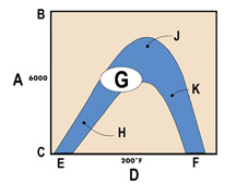
Refer to (fig. 2), How Driving Style Affects Oil Life.
A - Mileage Between Oil Changes
B - Long Trip
C - Short Trip
D - Engine Temperature
E - Cold
F - Hot
G - Typical Driver
H - Trips Less Than 2 Miles (3.2 km)
J - Highway Driving
K - Trailer Towing
Scheduled Maintenance
When the CHANGE ENGINE OIL light or message comes on, it means that service
is required on the vehicle. It should be serviced as soon as possible
within the next 600 miles (1000 km). It is possible that, under the best
conditions, the engine oil life system may not indicate that vehicle
service is necessary for over a year. However, engine oil and filter
must be changed at least once per year, and at this time the system must
be reset.
NOTICE: The owner should check oil regularly and keep it at the proper
level. Failure to keep the oil at the proper level can cause damage to
the engine not covered by warranty.
TIP: If the engine oil life system is accidentally reset, the vehicle
must be serviced within 3000 miles (5000 km) since the last service.
Reset the oil life system when the oil is changed.
Required services are described by the terms Maintenance I and Maintenance
II. (fig. 3) Generally, the first service should be Maintenance I, the
second should be Maintenance II, and alternated between I and II thereafter.
In some cases, Maintenance II may be required more often.
Maintenance I -- Use Maintenance I if the CHANGE ENGINE OIL light comes
on within 10 months since the vehicle was purchased or Maintenance II
was performed.
Maintenance II -- Use Maintenance II if the previous service performed
was Maintenance I. Always use Maintenance II whenever the light comes
on 10 months or more since the last service, or if the light has not
come on at all for 1 year.
Fig. 3 Typical Maintenance Schedules
Service |
Maintenance I |
Maintenance II |
| Change engine
oil and filter. Reset oil life system. |
X |
X |
| Lubricate
chassis components. |
X |
X |
| Visually check
for any leaks or damage. |
X |
X |
| Inspect engine
air cleaner filter change indicator. If necessary, replace filter. |
X |
X |
| Rotate tires
and check inflation pressures and wear. |
X |
X |
| Inspect brake
system. (a) |
X |
X |
| Check engine
coolant and windshield washer fluid levels and add as needed. |
X |
X |
| Perform any
needed additional services. |
X |
X |
| Inspect suspension
and steering components. (b) |
- |
X |
| Inspect engine
cooling system. (c) |
- |
X |
| Inspect wiper
blades. (d) |
- |
X |
| Inspect restraint
system components. (e) |
- |
X |
| Lubricate
body components. (f) |
- |
X |
| Check transmission
fluid level and add fluid as needed. |
- |
X |
Additional Required Services
Refer to the Typical Additional Required Services table. (fig. 4)
These services should be performed at the first maintenance service
(I or II) after the indicated miles (kilometers) shown for each item.
This table is a typical example. See the individual vehicle maintenance
schedule for specifics.
" Mileage intervals and services vary with
model line."
Fig.
4 Typical Additional Required Services
Service |
25,000
(41,500) |
50,000
(83,000) |
75,000
(125,000) |
100,000
(166,000) |
125,000
(207,500) |
150,000
(240,000) |
| Inspect fuel
system for damage or leaks. |
X |
X |
X |
X |
X |
X |
| Inspect exhaust
system for loose or damaged components. |
X |
X |
X |
X |
X |
X |
| Change automatic
transmission fluid and filter (severe service). (h) |
- |
X |
- |
- |
- |
- |
| Change automatic
transmission fluid and filter (normal service). |
- |
- |
- |
X |
- |
- |
| Change transfer
case fluid. |
- |
X |
- |
X |
- |
X |
| Replace spark
plugs and inspect spark plug wires. |
- |
- |
- |
X |
- |
- |
| Inspect positive
crankcase ventilation (PCV) valve. |
- |
- |
- |
X |
- |
- |
| Engine cooling
system service (or every 5 years, whichever occurs first). (i) |
- |
- |
- |
- |
- |
X |
Maintenance Footnotes
Maintenance footnotes may vary between vehicles. The following apply
to the typical schedules above, and have been condensed. They are
presented here only as an example. See individual vehicle maintenance
schedules for details.
a. Visually inspect brake components.
b. Visually inspect front and rear suspension and steering, CV joints,
boots and axle seals.
c. Visually inspect hoses.
d. Visually inspect wiper blades.
e. Check operation of seat belt system parts.
f. Lubricate locks, hinges, latches, seat hardware.
g. Add fluids as needed.
h. Change automatic transmission fluid if dictated by operating conditions.
i. Drain, flush and refill cooling system.
Owner Checks and Services
The owner is instructed to perform certain checks and services at specified
intervals, with the assistance of their GM Goodwrench dealer if desired.
These typically include:
- Engine oil level check
- Engine coolant level check
- Tire inflation check
- Starter switch check
- Automatic transmission shift lock control system check
- Ignition transmision lock check
- Parking brake and automatic transmission park (P) mechanism check
- Underbody flushing service
-
Thanks to Jerry Garfield and Chuck Burns
|
| |
figure
2
|
|
|
|
|
| return
to Table of Contents |
|
| Tracker
Windshield Replacement |
Owners
of some 2002 - 03 Chevrolet Trackers may comment that the windshield
has a crack in the lower left hand or right hand corner.
This condition may be caused by excessive sealant that can create an
uneven surface for the windshield to adhere to and may cause a stress
crack.
Service Bulletin 03-08-48-001, issued January, 2003 provides windshield
replacement procedures.
TIP: Do not use the dura-lock tabs that may be present.
- Thanks to Bill Denton |
|
|
| return
to Table of Contents |
|
| A
New Kind of Oxygen Sensor |
Some Background
The "conventional" O2 sensor in use since 1978 can tell the
engine control system only that the exhaust is either too rich or too
lean. It’s called a switching sensor because it makes a sharp
voltage transition when the air/fuel mixture varies a tiny amount
either side
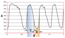
of ideal (14.7:1 for a gasoline engine). (fig. 5)
Refer to figure 5, Typical Switching-Style O2 Sensor Signal.
A. O2 Voltage (mV)
B. Time (s)
C. Rich-Lean
D. Lean-Rich
The engine controller responds to a rich signal from the O2 sensor by
leaning the mixture, and responds to a lean signal by richening the mixture.
Even more precise fuel control would be possible if the O2 sensor could
detect the exact deviation of the exhaust stream, lean or rich. The new
wide-range air/fuel sensor can do this.
Wide-Range Air-Fuel Sensor (WRAF)
The wide-range air-fuel sensor, or WRAF sensor, discussed in this article
will be used in the 4.6L LH2 engine in the 2004 Cadillac XLR and SRX.
This sensor may also be referred to as a lambda sensor or wide-band sensor.
The WRAF sensor has been used in the past on select models of GM vehicles
with the 3.0L L81 engine, first in the 1999-2001 Cadillac Catera, then
in the 2000-2004 Saturn LS.
TIP: Throughout service information, the wide-range air-fuel sensor is
referred to using the standard terminology of heated oxygen sensor or
HO2S; in this article we will refer to it as the WRAF sensor.
Advantages of the WRAF
A typical V6 engine operating at 2500 rpm will produce approximately
62 cylinder pulses per second per cylinder bank. Refer to the graph in
figure 5, which displays the voltage of a switching-style oxygen sensor.
During one rich-to-lean and lean-to-rich transition of the oxygen sensor
signal (1/2 second), there will be approximately 30 cylinder pulses.
Each cycle or switch is the average air-fuel ratio of several cylinders.
With a switching-style sensor, the engine controller will merely continue
to adjust fuel trim, rich or lean, until it sees a signal swing in the
opposite direction. The process then reverses and continues transitioning
rich-to-lean and lean-to-rich. This explains the constant cycling
or switching of the switching-style sensor.
So, the first advantage of the WRAF sensor is that it can detect the
exact deviation from 14.7:1, rich or lean, and allow the engine controller
to precisely adjust the air-fuel ratio to the desired amount.
TIP: Ideal combustion occurs with an air-fuel ratio of 14.7:1, also referred
to a stoichiometric.
Most switching-style oxygen sensors operate within a range of 0 to 1000
millivolts, and as a result will not provide an accurate reading when
the air-fuel ratio exceeds approximately 14.6:1 when rich or 14.8:1 when
lean.
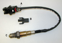
The WRAF sensor (fig. 6) can provide an accurate signal when the air-fuel
ratio is as lean as 16:1 or as rich as 11:1, allowing the engine controller
to continuously adjust fuel trim throughout this wide range of air-fuel
ratios. So, a second advantage of the WRAF sensor is its ability to provide
an accurate signal while operating in an air-fuel ratio, or lambda state,
other than stoichiometric .
Refer to figure 6, WRAF Sensor.
A. Trimming Resistor
B. Resistor Cover
C. Sensor
WRAF Wiring and Circuits
Refer to figure 7, WRAF Sensor Cutaway.
The WRAF sensor has six wires (circuits), divided among three functions.
Reference Voltage -- The engine controller provides a fixed signal voltage
to the WRAF sensor on two circuits. These circuits are called the reference
voltage circuit (D) and the low reference circuit (E) from the reference
air duct (P).
Pump Current -- There are two circuits called the input pump current (F) and
output pump current (G). They provide an electromotive force needed for the movement
of oxygen ions inside the sensor.
Heater (N) -- As with a switching-style sensor, there are heater voltage supply
(L) and heater low control (K) circuits. They are similar in operation to most
switching-style sensors.
Each sensor contains a trimming resistor (M) that is integral to the sensor connector.
This trimming resistor is used during sensor manufacturing to calibrate each
sensor to the desired performance specifications.
Operation
Here is what happens as exhaust flows past the sensor. Refer to the WRAF sensor
cutaway (fig. 7):
1. As the exhaust stream (A) passes the WRAF sensor, a sample of the exhaust
gases enters the exhaust gas sample tube (B) and moves through the diffusion
gap (C).
2. When the air-fuel ratio of the sampled exhaust gas changes, there is a corresponding
change to the voltage potential between the reference voltage circuit (D) and
the low reference circuit (E).
3. When the voltage on these circuits changes, the engine controller changes
the amount of voltage on the input pump current circuit (F) and the output pump
current circuit (G).
4. As the voltage on the input and output pump current circuits changes, oxygen
ions move into or out of the pumping cell (H) through the porous layer (J). This
brings the voltage potential between the reference voltage and low reference
circuits back to a desired value.
5. By monitoring the required voltage and current level change on the input pump
current and output pump current circuits, the engine controller can determine
what the air-fuel ratio is at that moment.
6. The engine controller can then determine exactly how much the air-fuel ratio
needs to be adjusted to maintain the desired voltage potential and thus the desired
air-fuel ratio.
The WRAF sensor is able to determine the exact amount of air-fuel ratio change
required for the upcoming cylinder pulses. This is different from a switching-style
sensor, which has a much larger estimating error of the air-fuel ratio change.
On a low level, there is closed-loop operation between the engine controller
and the WRAF sensor pumping circuits, low reference circuit, and reference voltage
circuit.
On a high level, there is closed-loop operation between the exhaust sampling
of the WRAF sensor and total fuel trim adjustment. The latter is similar to the
most traditional closed-loop fuel systems.
How to Interpret WRAF Sensor Data on the Tech 2
TIP: Even though the engine controller and the WRAF sensor use various voltage
levels during operation, the signal value displayed on the Tech 2 is a lambda
value, NOT a voltage value.
The variable name “lambda” refers to the deviation above or below
stoichiometric, or 14.7:1 air-fuel ratio. A lambda value of 1.000 is equivalent
to a perfect stoichiometric ratio of 14.7:1. Depending on vehicle platform,
the lambda value can be as low as 0.750 or as high as 3.999. A low lambda
value represents
a rich exhaust sample, and a high lambda value represents a lean exhaust
sample.
The lambda value can be used to calculate the exact air-fuel ratio.
For example, a lambda value of 1.025 on the scan tool indicates that the system
is operating lean. To find out exactly how lean, multiply 1.025 by 14.7. This
gives the result of approximately 15.07:1. Conversely, a lambda value of 0.975
indicates the system is operating rich. Multiply 0.975 x 14.7 = 14.33:1. This
gives you an idea of how the controller is able to determine the exact desired
air-fuel ratio.
The Meaning of Extreme Lambda Values
How can a lambda value of 0.750 or 3.999 be meaningful? Multiply a lambda value
of 3.999 x 14.7 = 58.79:1. This is clearly not an air-fuel ratio that any engine
could operate under during cruise or acceleration.
Extreme lambda values are a result of the limits of the controller hardware and
software. When a vehicle enters a fuel cut-off state during deceleration, the
lambda value may move to a very high number (infinity) because the controller
software and hardware are operating the pumping circuits at their maximum correction
state to offset the extremely lean air-fuel ratio that is occurring. The controller
software will not display infinity but will instead display a large number. Depending
on the controller manufacturer, these maximum limits may be as low as 0.750 during
a very rich condition, or as high as 3.999 during a very lean condition.
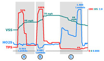
Typical WRAF Sensor Lambda Values (fig. 8)
Acceleration and Cruise -- The lambda value stays fairly flat, close to 1.000,
during the moderate to heavy acceleration and during cruise (A).
This is because the sensor and the engine controller are in their own closed-loop
operation and
the lambda value only “drifts” above or below 1.000 as the engine
controller makes its fuel trim adjustments. This closed-loop operation between
the engine controller and the WRAF sensor is an instantaneous reaction to
voltage deviations between the reference voltage circuit and low reference
circuit
and the resulting oxygen ion exchange via the pumping circuits.
Power Enrichment -- The lambda value moves lower when power enrichment is active
(B).
Deceleration -- During deceleration, the lambda value moves to 1.989. This is
because the engine controller has commanded a deceleration fuel cut-off state
and, as a result, the exhaust stream is extremely lean (C). Notice how the engine
controller will regulate the closing of the throttle; the throttle plate must
be less than five percent open before the lambda value will finally move to 1.989.
On this particular vehicle, 1.989 is the limiting value of the hardware and software.
Diagnosing a WRAF Sensor
Here are a few points to remember when diagnosing a WRAF sensor:
- With the sensor disconnected and the ignition on, the voltage level measured
on the input pump current circuit or the output pump current circuit, on the
engine harness side, is very low and should be measured using the DMM millivolts
scaling.
- In addition to the input and output pump current circuits, with the sensor
disconnected and the ignition on, there will be a voltage present on the reference
voltage circuit, low reference circuit, and possibly the heater low control circuit.
The applicable DTC tables, when necessary, will provide the exact voltage values.
Of course, there will be battery voltage present on the heater ignition voltage
supply circuit.
- The voltage that may be present on the heater low control circuit is a diagnostic
voltage produced by the engine controller. This voltage is used by the engine
controller to discriminate between a heater circuit open, short to ground, or
short to voltage condition. Depending on platform, the diagnostic voltage may
or may not be present.
- Remember this when performing voltage measurements on the engine harness side.
When a circuit fault is present, it may cause voltage level changes on the input
pump current, output pump current, reference voltage or low reference circuits.
So, you must not assume that because the voltage of the first circuit you measured
is not within the correct range it is the problem circuit!
- As with any heated oxygen sensor, no circuit repairs should be attempted to
the sensor harness.
-
Thanks to Jim Hanna
|
figure
5
|
figure
6
|
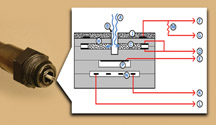
figure 7
|
figure
8
|
| return
to Table of Contents
|
|
Bulletins – April,
2003
This review of service bulletins released through mid-April lists the
bulletin number, superseded bulletin number (if applicable), subject
and models. |
Program
Bulletin
03011; Remote Keyless Entry System Inoperative; Specified 2003 Cadillac,
Chevrolet, GMC Pickups and Utilities; Hummer H2
Recall Bulletin
03-008; Driver Air Bag Inflator; 2003 Buick Rendezvous, Cadillac DeVille,
Chevrolet Venture, Impala, Monte Carlo, TrailBlazer, EXT, GMC Envoy,
XL, Pontiac Montana
00 – General Information
03-00-91-001; Vibration Analysis Worksheet; 2003 and Prior Passenger
Cars and Trucks, Hummer H2
01 – HVAC
03-01-39-001; Rear HVAC Blower Control Knob May Fall Off (Install New
Design Knob); 1998-2001 Cadillac Seville
03 – Suspension
01-03-08-002A; replaces 01-03-08-002; Front Suspension Clunk/Rattle Noise
Diagnosis; 1998-2003 Chevrolet Malibu, Oldsmobile Cutlass, Alero, Pontiac
Grand Am
03-03-07-001; Revised Wheel Alignment Specifications; 2003 Chevrolet
Silverado GMC Sierra 1500
04 – Driveline Axle
02-04-21-002A; replaces 02-04-21-002; Service 4WD Indicator Illuminated,
DTC B2725 Set, Transfer Case Selector Switch in One Position -- Indicator
Lamp Indicates Another Range is Selected (Replace Transfer Case Shift
Control Switch); 2002-03 Chevrolet TrailBlazer, EXT, GMC Envoy, XL, with
4-Wheel Drive
02-04-21-005A; replaces 02-04-21-005; Slips in 4-Wheel Drive, Noise,
Vibration, Leaks, Hot Odor (Diagnose and Repair Front Differential and/or
Transfer Case; Specified 1998-2003 Pickups and Utilities with Autotrak
Transfer Case (RPO NP8) (Selector Pad on Instrument Panel Must Have Auto
4WD, 4HI, 4LO, and 2HI Selections)
02-04-21-008A; replaces 02-04-21-008; Shudder, Rocking Motion, Binding,
Feels Like Vehicle is Stuck in 4WD (Crow Hop) when Turning at Low Speeds
(Replace Transfer Case Encode Sensor and Reprogram TCCM); 2002-03 Chevrolet
TrailBlazer, GMC Envoy, Oldsmobile Bravada
03-04-17-002; Whine Noise From Rear Axle (Diagnose and Replace Rear Propeller
Shaft with New Tuned Torsional Damper Rear Prop Shaft); 2002-03 Chevrolet
TrailBlazer, GMC Envoy, Oldsmobile Bravada with 4.10 Ratio Rear Axle
(Standard Short Wheelbase ) (RPO GT5)
03-04-17-003; Vibration/Noise from Auto/Manual Shifter During Drive/Gear
Shifts (Replace Front Prop Shaft to Transmission Flange Retaining Bolts);
2003 Cadillac CTS
03-04-17-004; Revised Prop Shaft Replacement Procedure; 2003 Cadillac
CTS
03-04-18-001; Availability of New Front Drive Axle Nut; 1997-2003 Chevrolet
Malibu, Oldsmobile Alero, Pontiac Grand Am
03-04-19-001; Use of Synthetic Front Axle Lubricant for 4WD Vehicles
Sold in Cold Weather Climates; Specified 2002-03 Chevrolet and GMC Pickups
and Utilities with 4WD and 9.25-inch Front Axle Assembly
03-04-19-002; Squeak, Squeal or Whistle Noise from Front Axle (Replace
Intermediate Axle Seal and/or Differential Carrier Seal); 2002-03 Chevrolet
TrailBlazer, GMC Envoy with 4WD, Oldsmobile Bravada AWD
03-04-21-001; 4WD Light, 4WD Inoperative, DTCs C0327, P0836, P5000 (Permanent
Fix Not Available At This Time); 2003 Chevrolet and GMC Pickup and Utility
with NP1 (NVG 263EAU), NP8 (NVG 246EAU) Transfer Case
06 – Engine/Propulsion System
01-06-04-002A; replaces 01-06-04-002; CEL Concern -- DTC P0101 Set (Reprogram
PCM); 2000 Cadillac DeVille, Eldorado, Seville with 4.6L Engine (VINs
9, Y -- RPOs L37, LD8)
03-06-01-005; Revised Crankshaft Rear Oil Seal Replacement, Crankshaft
Rear Oil Seal Installation and Special Tools; 2003 Cadillac DeVille,
Seville, Oldsmobile Aurora
03-06-01-006; Powertrain Qualilty Center for Performance Parts Engine
Replacements; 2003 and Prior Passenger Cars and LD Trucks, Hummer H2
03-06-01-008; Crankshaft Rear Oil Seal Leaks During Extreme Cold Weather
Operation (Modify Oil Separator); 2002-03 Chevrolet and GMC C/K, C4500/5500
with 6.6L Duramax Diesel Engine (VIN 1 -- RPO LB7)
03-06-03-003; AC Delco Replacement Battery Warranty Procedures; 2003
and Prior Passenger Cars and Trucks, Hummer H2
03-06-04-014; Oil Present Around Turbo Area, Oil Level Low, Oil Pressure
Gauge May Drop (Inspect/Replace Turbo Oi Feed Pipe Assembly); 1999-2002
Chevrolet and GMC MD Tilt Cab Models with 6HK1T Diesel Engine (VIN 3
-- RPO LG4)
03-06-04-015; Revised Engine Cranks but Does Not Run Diagnostic; 2002-03
Chevrolet Silverado, Suburban, GMC Sierra with 5.3L Engine (VIN Z --
RPO L59)
07 – Transmission/Transaxle
02-07-30-051A; replaces 02-07-30-051; Transmission Shifting In and Out
of 4th and 5th Gear (Hunting) When Pulling/Carrying a Load, Unable to
Manually Select 4th Gear (Install 5th Gear Inhibit Switch); 2001-02 Chevrolet
and GMC HD2500/HD3500 with 6.6L Diesel or 8.1L Gas Engine (VINs 1, G
-- RPOs LB7, L18) and Allison Auto Trans (RPO M74)
03-07-30-004; Introduction of New AISIN Transmission Quality Center;
2001-03 Chevrolet and GMC MD Tilt Cab Models with 4HE1-TC Diesel Engine
and AISIN Auto Trans
03-07-30-005; SES Indicator Illuminated; Transmission Slips, Engine Flare,
Delayed 2-3 Shifts, Shifts Missing, No Shift, DTC P0730, P0756, P0757
(Replace Accumulator Assembly/Service Transmission); Specified 2002 Chevrolet
and GMC Pickups and Utilities with 4L80E (MT1) or 4L85E (MN8) Auto Trans
08 – Body and Accessories
01-08-50-014A; replaces 01-08-50-014; Driver’ Seat Back Material
Pulling Away from Side Impact Air Bag Module Bezel (Replace Side Impact
Air Bag Bezel/Retainer); 2001-03 Chevrolet Monte Carlo
02-08-44-020B; replaces 02-08-44-020A; No Audio Out of Speakers at Times
(Reprogram Radio and/or Replace Amplifier); 2003 Cadillac, Chevrolet,
GMC Pickups and Utilities, Hummer H2
03-08-44-005; Poor Radio Reception or Radio Static/Increased Interference
with Rear Window Defogger On or Some Window Defogger Grids May Be Inoperative
(Diagnose and Repair Rear Window Defogger Heating Grid); 1997-2003 Buick
Century, Regal, Chevrolet Impala, Monte Carlo, Oldsmobile Intrigue
03-08-44-006; Revised Entertainment Information for Class 2 Radios; 2002
Chevrolet Blazer, S-10, GMC Jimmy, Sonoma
03-08-50-005; Front Heated Seat Inoperative/Cold (Replace/Install Seat
Heat Element); 1997-2002 Cadillac DeVille, Seville, Eldorado with RPO
KA1
03-08-50-006; Uncomfortable Front Seat Cushions (Reposition Cushion Trim
Cover); 2002 Pontiac Bonneville
03-08-52-001B; replaces 03-08-52-001A; Remote Keyless Entry System Inoperative
(Reprogram Passenger Door Module); Specified 2003 Cadillac, Chevrolet
and GMC Pickups and Utilities, Hummer H2
03-08-59-001; Ratle Noise from Front Center of Dash Area (Reroute/Insulate
Accelerator Cable); 2002-03 Chevrolet Cavalier, Pontiac Sunfire with
2.2L Engine (VIN F -- RPO L61)
03-08-98-001; Bubbles in Paint Around Perimeter of Roof (Replace Roof);
1999-2002 Chevrolet Camaro, Pontiac Firebird
03-08-110-002; Sun Visors May Not Stay in Extended Position (Replace
Sun Visors and Retainers); 1997-2003 Buick Century, Regal
03-08-131-001; Power Take-Off Description of Operation and Programming;
2003 Chevrolet Kodiak, GMC Topkick with PTO
09 – Restraints
02-09-40-005A; replaces 02-09-40-005; Availability of Rear Seat Shoulder
Belt Comfort Guides; 2003 Buick Century, Regal, Pontiac Grand Prix, Cadillac
Escalade, EXT; Chevrolet Avalanche, Silverado, Suburban, Tahoe, TrailBlazer
EXT, GMC Envoy, Sierra, Yukon, XL
03-09-40-001; Squeak Type Nose Coming from Inside Front Seat When Seat
Belt is Moved (Fix Not Yet Available); 2003 Cadillac CTS
|
| return
to Table of Contents |
|
