| |
 |
Note: Clicking
on any picture or illustration will open a larger version of that art.
|
|
Navigating
the Upgrades in SI for 2005 |
First,
a Little History
GM on-board computer systems have come a long way since the Computer
Command Control (CCC) system first appeared in the early 1980s.
As time passed, additional modules were added to operate anti-lock brakes,
air bags, body control functions, HVAC, entertainment, and other functions.
Sophistication was multiplied when the modules were allowed to communicate
with each other using the Class 2 network, and more recently GMLAN.
The original CCC-era ECM was reprogrammed by removing the PROM “chip”
(programmable read-only memory) and plugging in a replacement. Many
of the current modules need to be programmed or set-up before use. Often,
this requires use of a scan tool and downloading data from the Techline
terminal.
Through all of this hardware evolution, the service manuals also evolved,
from paper manuals to the present web-based SI, and from having the
electronics isolated in their own service category to having them distributed
among the sub-systems they affect.
Moving Forward
Now, access to all control module integration information will be in
one central place in SI.
Beginning with the 2005 model year, the SI material for Vehicle Control
Systems is being considerably enhanced for each and every vehicle line.
We’ll focus on the Chevrolet Equinox because it is the first 2005
model available in SI. (fig. 1)
TIP: Even though
you may not work on Equinox vehicles, we suggest you follow along in
the Equinox sections of SI. As other 2005 vehicles are available in
SI, the reorganization information will apply to them as well.
TIP: SI will
contain more information than before, but because some service categories
are being moved and condensed, you may not find the information where
you expect to find it. Here are the details.
How the New Organization Works
For this example, begin by “building” the vehicle in SI.
In the category choices, you will see Vehicle Control Systems. This
should always be your starting point. The paths look like this (the
heading lists here have been abbreviated for simplicity):
| -
“Build” the vehicle |
| -
Select the Service Manual |
| -
Vehicle Control Systems |
| |
-
Vehicle DTC Information |
| |
|
-
Diagnostic Information and Procedures |
| |
|
|
-
Diagnostic Starting Point -- Vehicle |
| |
|
|
-
Diagnostic System Check -- Vehicle |
| |
|
|
-
Diagnostic Trouble Code (DTC) List -- Vehicle |
| |
|
|
-
Symptoms -- Vehicle |
| |
-
Computer/Integrating Systems |
| |
|
-
Diagnostic Information and Procedures |
| |
|
|
-
Diagnostic Starting Point |
| |
|
|
-
Scan Tool Information |
| |
|
|
-
DTCs and Symptoms for: |
| |
|
|
|
-
Body Control Systems |
| |
|
|
|
- RAP |
| |
|
|
|
- Data Link
Communications |
| |
|
|
-
Control Module References |
| |
|
|
-
Data Link References |
| |
|
-
Repair Instructions |
| |
-
Programming and Setup |
TIP:
There appear to be some redundancies in the above
list, such as Diagnostic Starting Point being listed two places. They’re
linked to the same place, so no matter where you start, you’ll
end up in the correct place.
In the following paragraphs, we’ll describe some of the highlights
of this new organization.
Computer/Integrating Systems
Let’s get this one covered right away. When you look for the Body
Control Systems, Data Link Communications, and Retained Accessory Power
information in Body, you’ll discover that these service categories
are no longer in the index.
Don’t panic. The details are still there; they’ve just been
moved to Computer/Integrating Systems in Vehicle Control Systems.
Focus on the Vehicle
Traditionally, you’ve begun diagnosing a system by performing
a Diagnostic System Check. Because systems are now thoroughly integrated
(interrelated), systems no longer operate independently of other systems.
Most everything is a part of a vehicle-wide network. Diagnostic System
Checks have been deleted from individual service categories. So, diagnosis
now starts with a Diagnostic Starting Point -- Vehicle
and is followed by the Diagnostic System Check -- Vehicle.
The Diagnostic Starting points will also remain in the various service
categories to guide you to the Diagnostic System Check --
Vehicle in the event that you don’t know where to
start.
TIP: The Vehicle
Diagnostic System Check looks specifically for vehicle-wide conditions
that can affect operation of more than one module, such as communication
problems and voltage problems.
If a DTC is set, you will be directed to the Diagnostic
Trouble Code (DTC) List -- Vehicle. This list contains
every DTC that can be set by any module on the vehicle. Simply scroll
the list to reach the desired DTC.
TIP: Because
the DTC list is quite long, you may wish to use the search function
to locate the desired DTC. Press Control F. Fill in what you want to
search for, specify matching parameters if necessary, and select which
direction to search. Click the Find Next button to begin your search.
The DTC list contains two important and useful features. First, it includes
a descriptor for each code. Second, it includes
a link to the diagnostic procedure needed
to determine why the DTC was set.
TIP: DTC lists
have been deleted from individual service categories.
DTC Descriptors
In addition to being on the DTC List -- Vehicle, the descriptor for
each DTC will be included in the facing page of its diagnostic table
document. The descriptor is a text description of what the DTC number
represents.
Control Module References
This heading, found under Computer/Integrating Systems is the heart
of the new organization. Click on this link and you will see a table
that includes every module that can be installed on the vehicle you’re
working on. For each module, you will find links to schematics, repair
instructions and programming and setup.
TIP: This table
includes every component that has “Control Module” in its
name, regardless of whether the component can be programmed, set-up
or configured. It also includes every other component that can be programmed,
set-up or configured, even though “Control Module” is not
a part of its name.
TIP: If you begin
your repair by following diagnostic steps, you will be brought to the
Control Module References table, if the diagnostic directs you to replace
or reprogram a control module.
Schematic Links -- Clicking on a link will take you
to the wiring schematic that includes the selected module. You may find
this information useful both in diagnosis and in repair.
Repair Instruction Links -- Clicking on a link will
take you to the appropriate document in SI for replacement instructions
for the selected module.
Programming and Setup Links -- Clicking on a link will
take you to the appropriate procedure for either programming or setting
up the selected module. If no programming or set-up is required, you
will be told this as well. You will not be left wondering.
Data Link References
Vehicles that have multiple data communication links include this feature.
This document details which control modules communicate on which data
links (i.e., Class 2, GMLAN, etc.) and link you to the appropriate diagnostic
for a communication problem for that control module.
Programming and Setup
The simplest way to describe the changes here is to say that access
to all the information you need to make the vehicle perform properly,
after a control module repair, is conveniently organized.
TIP: This section
was previously called Programming and contained only generic SPS programming
information.
TIP: You can
reach this section either by selecting it directly from Vehicle Control
Systems, or you can be led here from the Control Module References table.
Here, you’ll find instructions for programming or setting-up each
module that requires such a procedure.
TIP: Diagnostics
assume that you start with a vehicle that has the correct control modules
with the correct calibrations and configurations. A recent component
replacement or reprogramming event without the proper programming or
setup procedures may be the source of the concern with the vehicle.
-
Thanks to Kevin Fondaw and Andrew Fegan |
|

figure
1 |
|
|
| |
|
|
| return
to Table of Contents |
|
|
| Service
Information Discontinues Win 98 Support |
Late last year, GM Service and Parts Operations announced the Techline
end-of-life support policy for Windows 98 starting January 15, 2004
(see TechLink Dec. 2003). A minimum PC specification and browser information
were included as part of this communication. This change ensures optimal
performance for Techline applications.
Until now, the impact has been minimal. However, in May, a new set of
Service Information (SI) CDs will be shipped to all US dealers. Instructions
will indicate the compatible operating systems (Windows 2000 and XP
Professional) and the minimum PC hardware configuration.
During installation of the application, SI will detect the operating
system. If Windows 98 or ME are detected, SI will not load. Instead,
SI will advise the user that the operating system is incompatible.
Going forward, all releases of SI and LTG will be affected by this change
including the June 1, 2004 GM Labor Time Guide.
If you plan to upgrade your PC, please follow these tips:
TIP: Before upgrading
PC hardware or the operating system, review the Techline minimum PC
specification on http://service.gm.com.
TIP: It is recommended
to use a full operating system installation rather than an upgrade.
Use of an upgrade may affect proper functionality of SI.
TIP: Those who
wish to continue using Windows 98 (or ME) are encouraged to use the
SI web site.
Additional information can be found at http://service.gm.com
under the Techline tab.
-
Thanks to Lisa Scott |
|
|
|
|
New TIS/Tech 2 Programming Feature |
An
article in the October 2003 issue of TechLink explained a new Tech 2
feature implemented in Diagnostics. It permits you to go directly to
Request Information in the Special Function menu. You don’t have
to leave Diagnostics, you won’t have to “re-build”
the vehicle, and only the module you’re working on is commanded
to download information.
The feature described in October was the first of several steps being
taken to make your Tech 2 more efficient to use.
Now, another step is being taken, effective with satellite-broadcast
TIS application version 4.1, released March 22. This software version
must be installed for this feature to work. The Tech 2 should be updated
to the latest version, 24.001.
Once Request Information is performed on the new module you’ve
just installed, you will then have to connect your Tech 2 to TIS to
download the latest calibrations.
TIP: This new
feature is not dependent on module replacement; it will work on existing
modules as well.
Here’s the new feature. The only controller you will see in the
Supported Controller list in TIS is the one you are working on. You
will not have to look for it.
TIP: When you
reconnect the Tech 2 to the vehicle to program the module, you must
use the Service Programming System menu. As always, follow all cautions
through the programming process. Also remember to check for any Set
Up, Crank Learn, Adapt Learn ABS and other procedures necessary to complete
the programming process.
- Thanks to Mark Stesney |
|
|
| |
return to Table of Contents |
|
| TIS
Version Explanation |
You
may be wondering how to determine the version number for various parts
of TIS (Techline Information System). For instance, Blockpoint, Satellite
Data Release, Tech 2 version, and month of release.
TIP: This information
applies to all GM Dealers networked through GM ACCESS. Stand-alone users
rely on CDs and web access for updates.
To check these version numbers, open the TIS application and go to “Help
/ About TIS 2000” to locate the following list.
About TIS
2000
1. North American Operations 04.1
2. Satellite Update/Mise a jour 4.0
3. Tech 2 Version 24.001
4. TIS2000 - NAO DATA-CD GM DAT 03/2004
The 04.1 is your blockpoint or software application version
number. The 04 indicates the year of the broadcast, and the .1 indicates
the version within that year. Blockpoints are normally broadcast on
a quarterly basis and include items for service and sales applications
in your GM dealership. Service applications include TIS (Techline Information
Systems) and SI (Service Information).
2. Satellite updates are data related, are
also broadcast and vary from monthly to bi-weekly. The first digit usually
indicates the month (1 = Jan, 2 = Feb) and the second digit indicates
the version number. Odd-numbered data updates (1.0, 3.0, 5.0) are broadcast
every second month. These odd-numbered data updates include new VINs,
calibrations and, most important, updates for your Tech 2. Look for
updates for your Tech 2 when you see an odd number.
Even-numbered data updates (2.0, 4.0, 6.0) include VINs and calibrations.
Incremental updates (3.25, 3.5) usually include VINs and calibrations.
Occasionally, a special or interim Tech 2 update will be included.
3. It’s important to know your Tech 2 version.
As described above, the Tech 2 must be updated on a regular basis. Tech
2 updates include added vehicle coverage, new applications and functionality,
fixes when necessary, and much more. Knowing the version number is helpful
when troubleshooting an issue with TCSC (Techline Customer Support Center)
or engineering. Numbering usually re-starts with .001 each year. For
instance, 24.001 was the first Tech 2 version release for this year.
23.011 was an interim release this year to address some special issues.
4. The 03/2004 indicates the month this particular data was released.
Bottom line: To make the most of your Techline software, which includes
TIS and SI, be sure you are working with the most current update.
-
Thanks to Mark Stesney
|
| |
| |
| return
to Table of Contents |
|
| Rear
Cupholder Latch |
1999-2002 Chevrolet Avalanche, Silverado, Tahoe, Suburban, GMC, Sierra,
Yukon, Yukon XL and Cadillac Escalade, EXT equipped with a rear cupholder
in the center console may experience a broken cupholder latch. Do not
replace the middle console assembly. Order part number 88934982 Front
Floor Console Cupholder Latch in catalog group 16.650 and replace the
latch.
-
Thanks to Wesley Wood |
| |
| return
to Table of Contents |
|
| Sensing
and Diagnostic Module (SDM) Connector |
When
servicing an air bag (SIR) system, here’s how to remove and install
the SDM electrical connector without causing damage.
IMPORTANT
TIP: Observe
safety cautions in SI to avoid SIR deployment, personal injury,
or unnecessary SIR system repairs.
TIP: Disable
the SIR system. Refer to SIR Disabling and Enabling Zone in SIR.
TIP: Refer
to the appropriate section in SI for the complete procedure. This
may involve removing other vehicle components for access to the
sensing and diagnostic module (SDM). |
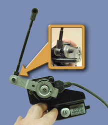
SDM Connector Removal
1. Pull out the red connector position assurance (CPA) from the SDM
connector.
2. Pull the slide retaining lock fully open from the SDM connector.
(fig. 2)
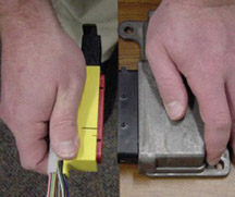
3. Grasp the SDM yellow connector by the connector housing. (fig.
3)
TIP: Do not grasp
slide retaining lock or wire bundle for removal.
4. Remove the SDM connector from the SDM while carefully maintaining
axial alignment.
TIP: Be careful
not to twist or rotate excessively when removing the connector, which
could cause damage.
SDM Connector Installation
The SDM must be installed to the vehicle according to SI procedures
before performing these steps.
TIP: Be careful
not to rotate the connector excessively when installing the connector
into position. Maintain proper alignment during the installation process.
1. Align and install the SDM connector onto the SDM.
2. Push the slide retaining lock fully closed to lock the SDM connector
onto the SDM.
TIP: If the slide
retaining lock is difficult to push, squeeze the center of the yellow
harness connector housing, to overcome a slight plastic interference
fit during the slide retaining lock assembly step.
3. Push in the red CPA into the SDM connector.
IMPORTANT
TIP: Refer
to the appropriate SIR section in SI for the complete procedure.
This may involve installing other vehicle components removed for
access to the sensing and diagnostic module (SDM).
TIP: Before
applying power to the SDM, make sure it is securely fastened, with
the arrow facing toward the front of the vehicle.
Enable the SIR system. Refer to SIR Disabling and Enabling Zone
in SIR.
The AIR BAG indicator may remain ON after the SDM has been replaced.
DTC B1001 may set, requiring the SDM part number to be set in multiple
modules. If the indicator remains ON after enabling the SIR system,
perform the diagnostic system check and follow the steps thoroughly
to ensure that the SDM is set properly. |
-
Thanks to Wesley Wood
|
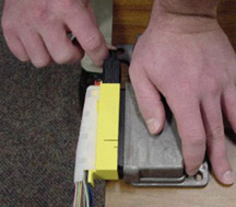
figure 2 |
| 
figure
3
|
| return
to Table of Contents |
|
| Do
Not Swap BCMs |
Although
most of us have done it occasionally, using parts from other vehicles
for test purposes has never been recommended. As vehicle systems become
more integrated, there are many instances where this practice is unacceptable.
In some cases installing parts from one vehicle into another will have
a negative effect not only on the test component(s) but on other components
in the vehicle. In some circumstances, this can lead to replacing components
that functioned perfectly before the test.
The following information applies to one specific instance -- the 2004
Colorado and Canyon pickups.
When diagnosing conditions in systems that involve the Body Control
Module (BCM), some technicians take a diagnostic shortcut by swapping
a known-good BCM into the vehicle being diagnosed.
IMPORTANT: DO
NOT swap the BCM from one vehicle to another for any reason.
First, this is not an acceptable procedure. Always follow the diagnostic
steps presented in SI.
Second, in the case of the Colorado/Canyon, swapping the BCM will cause
the following to occur:
- The radio will lock up.
- The Powertrain Control Module (PCM) will reset the Oil Life System
to 100.
- The PCM will set a P0315 (crank variation learn).
TIP: If a P0315
is set, you must run the crank variation relearn using the Tech 2 to
relearn the crank variation parameters.
The PCM will retain these conditions even if the original BCM is put
back into the vehicle. The radio will unlock, however.
IMPORTANT: DO
NOT swap the BCM from one vehicle to another for any reason.
-
Thanks to Devin Koski |
|
return
to Table of Contents |
|
| Parking
Brake Cable Noise |
This
information applies to Venture, Montana, and Silhouette models. During
2003, the rear parking brake cable retainer was repositioned to eliminate
rattle concerns. In some cases it may result in a metallic noise from
the left rear. This may be more pronounced on vehicles that do not have
electronic load leveler control, option G67. The parking brake cable
retainer is positioned directly above the rear trailing arm axle tie
rod and in some circumstances, contact may occur. If you encounter this
condition, install retainer part number 10408652. This park brake cable
retainer will avoid contact with the tie rod.
TIP: On vehicles
equipped with G67 load leveler, make sure the parking brake cable does
not rub on the position sensor or associated wiring. It may be necessary
to add conduit or tape to protect the wiring.
- Thanks to Tom Geist |
| |
| return
to Table of Contents |
|
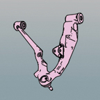
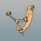
| Interchangeable
Control Arms |
Engineering has changed the design of the lower control arm used on
C/K HD trucks and the HUMMER H2.
The original A-shaped arms for the C/K HD were p/n 12475475/76 and 88982348/49
for the H2. The service arms for all vehicles are now the V-shaped arms.
The V-shaped arms are direct bolt-in replacements and require no special
treatment; they simply look different. The new V-shaped arms are p/n
15103878/79 for the C/K HD and 15103880/81 for the H2.
TIP: These are
the production as well as service part numbers and should not be mixed.
The bushing rate for the H2 arm is much firmer than that of the C/K
HD.
-
Thanks to Steve Love and Dan Stress
|
Service
V Arm |
C/K
|
15103878/79 |
| Service
V Arm |
HUMMER
H2 |
15103880/81 |
|
Original
Service
A Arm |
C/K |
12475475/76 |
| Original
Service
A Arm |
HUMMER
H2 |
88982348/49 |
|
|
|
|
return
to Table of Contents |
|
| XLR
HVAC After-blow |
A new software version for the HVAC module is available on the XLR to
update the functionality of the after-blow. The following procedure
allows you to offer this update to the customer.
TIP: After-blow permits
the HVAC blower to run for a pre-determined time period after the ignition
is turned off, to assist in drying the evaporator, to minimize odor.
Before programming, follow these steps to check the current software
status.
1. In Tech 2 Diagnostics, follow this path.
- 2004
- Passenger car
- Cadillac
- Y
- Vehicle Control Systems
- Computer/Integrating Systems
- ECU Identification Information
- HVAC
- Module Information 2
2. Observe the part numbers listed in Module Information 2. If the Software
Part Number displayed is 00BACD05 or the Calibration ID number displayed
is 00BACD06, perform steps 3, 4 and 5. If the Software Part Number displayed
is 00BAE5EA or the Calibration ID number displayed is 00BAE5EB, go directly
to step 5.
3. Go to TIS terminal and perform SPS calibration download procedure
for HVAC.
4. Go back to the vehicle and download new software into the vehicle.
5. Perform the Afterblow Enable Procedure in HVAC Systems-Automatic,
to enable after-blow on the HVAC module.
-
Thanks to Trish Zambo and Nolan Steinert |
|
|
|
return
to Table of Contents |
|
| Tire
Hoist Mechanism |
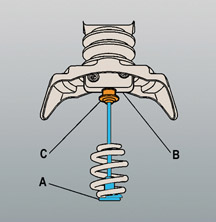
On
2003-04 C/K trucks, If the spare tire hoist has been fully raised without
a spare tire in place, the secondary latch mechanism may have become
engaged. If this has occurred, the hoist will not lower and the following
procedure will have to be performed. Refer to figure
6 for parts identification.
Turn the hoist shaft counterclockwise until approximately 15 cm (6 in)
of cable is exposed (A).
While holding the latch pin (B), fully depress the latch button (C)
and release the secondary latch from the hoist assembly. Some side-to-side
and/or up-and-down movement may be necessary to disengage the latch
mechanism.
Continue turning the hoist shaft counterclockwise to lower the hoist
the rest of the way.
- Thanks to Dan Oden |
figure
6 |
|
return
to Table of Contents |
|
| Quad-Band
Antenna |
A
new antenna will appear on the Cadillac SRX beginning this month (fig.7).
It has a plastic base and a stubby 3-inch (7.6 cm) mast. It is expected
that this antenna will see widespread use in future model years.
The antenna is called a quad-band because it incorporates four separate
antennas into one unit:
- XM radio
- OnStar GPS
- OnStar analog
- OnStar digital
Another similar unit, the tri-band, incorporates only the three OnStar
antennas.
TIP: This antenna
is not used for conventional AM/FM reception.
The quad-band antenna is installed to the vehicle’s roof much
like the typical XM antenna, although it has multiple cables.
TIP: Do NOT apply
paint or clear coat to the radio antenna. This will damage the function
of the antenna, causing poor reception or loss of reception of the XM
digital signal.
- Thanks to Jim Hughes |

figure
7 |
| return
to Table of Contents |
|
| Creak
Noise at Low Speed |
This
information pertains to 2004 Pontiac Bonneville, Buick LeSabre and Cadillac
DeVille.
Customers may comment about a creak noise that can be heard coming from
the rear end of the vehicle when driving at low speeds and making turns.
This noise can also be heard when performing parking-lot type manuvers.
The noise may be caused by the electronic level control sensor link
ball sockets (fig. 8). Clean and lubricate
the sockets with a non-water soluble type grease to eliminate the noise.
- Thanks to Bill Metoyer
GM
Vehicle Care Lubriplate |
89021668
(89021674 in Canada) |
GM
Vehicle Care Super Lube |
12346241
(10953474 in Canada) |
|
figure
8 |
| return
to Table of Contents |
|
| Odometer
Programming |
Starting
with model year 2004, odometer information for the Grand Prix is stored
in the Drivers Information Center (DIC) instead of the Instrument Panel
Cluster (IPC). When ordering a replacement DIC for a 2004 Grand Prix,
be sure you obtain the vehicle’s mileage and provide it to the
Electronic Service Center (ESC).
TIP: The odometer cannot be programmed into the DIC in the field. The
mileage must be programmed by the ESC before sending the DIC to the
dealer.
- Thanks to Steve Falko |
| return
to Table of Contents |
|
| Pictorial
Service Information, Part 2 |
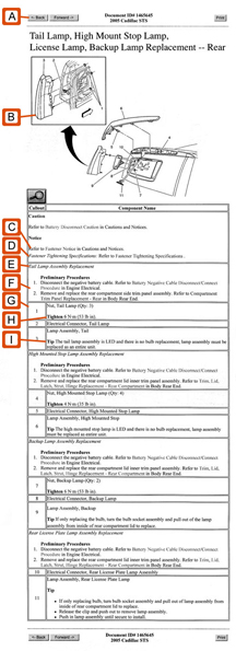
As
promised last month, here’s a sample of the new pictorial approach
being developed for SI.
A procedure printed from the SI website will typically run 2-3 pages,
considerably fewer than needed to print a procedure in the old format.
This example represents how Pictorial will look on the web version of
SI (fig. 9). Here are some highlights.
(A) Repair Title
(B) Illustration -- Disassembled view of the
components involved in the repair, shown in “vehicle context”
to indicate where they’re located. A callout number on each item
corresponds with a part in the procedure.
(C) Fastener Notice link -- Leads to standard
statement in Cautions and Notices
(D) Fastener Tightening Specifications link --
Leads to standard tightening statement
(E) Component Replacement
(F) Preliminary Procedures -- Steps that take
place before performing the repair. Lifing and Jacking is a good example.
(G) Callouts -- Each line in the repair table
contains information relevant to the numbered item shown in the illustration.
The item is named, noun first, using parts manual nomenclature.
The callouts may include supplemental information, such as:
(H) Tightening Specification
(I) Tip -- Insights and helps, as though being
shared by an experienced technician.
Caution, Notice
Special Tool Number
This new approach will be introduced this fall for the following vehicles:
- 2005 Cadillac STS
- 2005 Chevrolet Corvette
- 2005 Chevrolet Cobalt
- 2005 Mini Vans.
- Thanks to Bob Scherer |
figure
9 |
| return
to Table of Contents |
|
| Memory
Seat Modules |
This
information applies to 2004 C/K trucks with memory seat modules.
Modules are being replaced unnecessarily, perhaps due to misunderstanding
of proper operation. Here are some tips. This is a two-step process.
Enabling Using DIC
Seat memory is enabled using the DIC (Driver Information Center). When
the vehicle leaves the factory, the Seat Position Recall is set to the
OFF mode, which is the default. The Easy Exit Seat is also set to the
OFF mode, which is the default.
The Seat Position Recall moves the seat to the driver’s preferred
position according to which mode is enabled using the DIC:
OFF -- seat position is recalled when memory
button 1 or 2 is pressed.
KEY FOB -- seat position is recalled when the
key fob button is pressed
KEY IN -- seat position is recalled when when
the ignition key is installed.
When enabled, Easy Exit moves the seat rearward when the ignition key
is removed.
For the Seat Position Recall to function automatically, it’s necessary
to select either Key Fob or Key-In. For the Easy Exit Seat to function,
it’s necessary to select ON.
Setting Position in Memory
Setting the driver’s chosen seat position into memory is a separate
step. Adjust the seat to the desired position (also adjust mirrors, radio
presets, and other related functions if available), then press and hold
the Driver 1 button to store the information in memory. Repeat for Driver
2.
TIP: Observe if
the seat memories are operative before proceeding with diagnostic steps
for memory seat module replacement.
- Thanks to Paquita Bailey |
| |
| return
to Table of Contents |
|
| Power
Window Motor |
This
information from bulletin 04-08-64-003A applies to 1999-2004 full sized
trucks.
The power window motor assembly for the front doors can now be ordered
separate from the regulator. The motor and regulator assembly continues
to be available as well.
TIP: Use the
bolts included with the replacement motor. Discard the original attaching
parts.
-
Thanks to Steve Oakley |
| return
to Table of Contents |
|
| TAC
Corner |
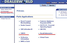
GMDealerworld
is a fast way to access recently released recall information (fig.
10).
The following are the steps log onto GM Dealerworld and obtain recent
bulletin, campaign and GM Messenger messages:
1. Go to the web and type http://www.gmdealerworld.com/
2. Enter your User name and password.
TIP: You may
need to establish this at the dealership. The dealership has a Partner
Security Coordinator that can provide or reset passwords for Dealerworld.
3. From the home page you are able to select: Recall Information,GM
Messenger, GM VISS, Calibration ID and SI.
-
Thanks to GM Technical Assistance |
figure
10 |
| return
to Table of Contents |
|
| Problem
with Radio Setup |
After
installing a radio in a 2004 Buick Rendezvous or Pontiac Aztek, you
may receive Calibrate or Error message on the radio or possibly a DTC
after what appears to be a successful radio setup.
Use 2003 as the model year in the Tech 2 and you should not receive
an error message or DTC.
This Tech2 software problem is being investigated for a resolution using
2004 as the model year on the above listed vehicles.
-
Thanks to Phil Race |
| |
| return
to Table of Contents |
|
| OnStar
Steering Wheel Controls |
After
the radio is replaced in a 2003-04 CTS or 2004 SRX with a non-navigation
radio option, the customer may complain that the steering wheel controls
for the OnStar are inoperative. When the customer presses the SWC button
to initiate OnStar Personal Calling (OPC), the radio will display AUDIO
MUTE instead of PHONE and the OnStar ready prompt is not heard.
Using the Tech 2, go to the radio under spec
al functions, set options, optional modules, then select OnStar and
save options. It is necessary to cycle the ignition off and open the
door to disable RAP to save programming.
-
Thanks to Amy Sutherland |
| return
to Table of Contents |
|
| Loose
Crankshaft Reluctor |
This
information applies to 2001-2004 Chevrolet and GMC C/K and MD C 4/5
trucks equipped with the 6600 Duramax LB7 Diesel Engine with rough,
unstable, incorrect idle speed or stall.
After completing the published diagnostics for an engine stall or misfire
with no trouble found, and the data indicates intermittent high balance
rates on random cylinders, check for a loose crankshaft reluctor.
To inspect the crank reluctor, remove the right inner fender, crank
sensor, and crank sensor spacer. Use a blunt probe and try to move the
reluctor clockwise or counter clockwise. If the crankshaft reluctor
is found loose, repair by replacing the necessary parts and be sure
to include the alignment pins.
-
Thanks to Jack McVoy |
| return
to Table of Contents |
|
| DVD
Technical Assistance |
This
information applies to 2002-04 Pontiac Montana, Chevrolet Venture and
Oldsmobile Silhouette.
Any calls on 2002 or newer U/X Van DVD entertainment system (that involve
the part itself) should be referred to Model Electronics Technical Assistance
at 800.433.9657 (in Canada, ACDelco Superstore).
-
Thanks to Amy Sutherland |
| return
to Table of Contents |
|
| Fuel Sender
Assembly Replacement |
A
2004 Chevrolet Malibu with 3.5L LX9 engine may experience the following
driveability symptoms after a fuel sender assembly replacement.
- intermittent stall
- stalls after filling with fuel
- fuel odor, or
- EVAP canister saturated with fuel
Refer to SI Document I.D Number 1245199, Fuel Sender Assembly Replacement.
Verify that step number 2 of the installation procedure was performed
correctly: connect the ventilation harness inside the fuel tank to the
bottom of the modular fuel sender cover.
-
Thanks to Duane Raymond |
| return
to Table of Contents |
|
 Car Issues – Fix It Right The First Time (new issues in bold)
 |
Model
Year(s) |
Vehicle
Line(s) --
Condition |
Do
This |
Don’t
Do This |
Reference
Information / Bulletin |
2001-2004 |
Aztek),
Rendezvous, Venture, Montana, Silhouette – Pop and/or Rattle
in Exhaust Down Pipe |
Follow
procedure in bulletin using clamp P/N on down pipe |
Don’t
replace converter assembly for rattle/buzz noise without completing
instructions in bulletin. |
03-06-05-003 |
2000-2003 |
LeSabre,
Park Avenue, Regal, Impala, Monte Carlo, Bonneville, Grand Prix
With 3.8L V6 Engine (RPO L36) – Loss of Coolant, Milky Colored
Oil |
Replace
upper intake manifold gasket only. |
Don’t
replace upper intake manifold assembly for coolant leak condition. |
03-06-01-016 |
2000-2004 |
All
Cars with 4T40/4T45E and 4T65E – Light On/Various Transmission
Codes Stores |
Check
transmission 20-way connector for secure connection (disconnect
and reconnect). |
Don’t
replace transmission, TCC PWM, VSS, PCS or valve body. |
02-07-30-022B |
1998-2004 |
Seville
– Heated Seat Inoperative |
Replace
only needed heating element. |
Don’t
replace entire seat cover if heated seat element is inoperative. |
01-08-50-002C |
2001-2004 |
Century/Regal
– Intermittent SES, ABS or TCS Lamp, No Crank/No Start,
Various I/P Cluster Intermittents, DTCs Set, Shifter Locked in
Park (BTSI Inoperative) |
Check
UBEC harness connectors for damage and replace damaged terminals. |
Don’t
replace UBEC, ignition switch, SDM, BCM, shifter assembly (Regal)
or intermittently inoperative clusters. |
03-08-45-004 |
2000-2004 |
Cavalier/Sunfire/Alero/Grand
Am – Inoperative Sunroof Module |
Retime
module or replace only motor for inoperative complaints. |
Don’t
replace entire sunroof module assembly. |
03-08-67-009A |
2003-2004 |
Cavalier/Sunfire
– Air Conditioning Compressor Noisy |
Inspect
for ground out conditions that can cause A/C compressor noise
complaints. |
Don’t
replace A/C compressor for excessive noise complaint without inspecting
for ground outs. |
03-01-38-012 |
1999-2004 |
All
Cars and Trucks – Brake Warranty, Service and Procedures |
Issue
One: Refinish brake rotor.
Issue Two: Measure for LRO |
Issue
One: Don’t replace brake rotors.
Issue Two: Don’t measure for LRO |
00-05-22-002C |
2003-2004 |
CTS
– Variable Effort Steering (VES) “Service Steering
Message,” DTC C1241 or C0450 |
Replace
only VES solenoid. |
Don’t
replace entire steering gear. |
03-02-36-001 |
2003 |
All
cars with 4T40/45E, 4T65E and 4T80E – Code P0742 |
Replace
TCC PWM Solenoid |
Don’t replace transmission, torque converter or valve body
assembly. |
02-07-30-039C |
|
| return
to Table of Contents |
|
|
 Truck Issues – Fix It Right The First Time (new issues in bold)
|
Model
Year(s) |
Vehicle
Line(s) --
Condition |
Do
This |
Don’t
Do This |
Reference
Information / Bulletin |
2002-2004 |
Fullsize and Midsize Pickups and Utilities – Sleepy New
Venture Gear Transfer Case Control Module |
Verify
sleepy module as primary cause, per bulletin. Reprogram TCCM with
latest software released 3/11/04. |
Don’t
replace encoder motor or transfer case. Replace module only if
C0550 DTC shows as current or history. |
02-04-21-006C |
2004 |
Fullsize Pickups – 6.6L LLY Diesel Engine Injectors |
04
LLY Duramax® fuel injector is on restriction. Contact TAC
before replacing injector. |
Do
not replace an LLY Duramax® injector before contacting TAC. |
GM
Messenger VSS20040067 |
2002-2004 |
Chevrolet Avalanche and Cadillac Escalade EXT – Cargo Covers
and Cladding Faded or Stained |
Thoroughly
clean, dry and treat components with “Armor-dillo.”
To order call 888.393.4722 or online at www.armor-dillo.net. |
Don’t
replace cargo covers for this condition. |
04-08-111-001 |
2002-2004 |
Fullsize
and Midsize Pickups and Utilities – Transfer Case CNND Labor
Operation |
Use
Labor Operation K9993 for transfer case issue on 4WD or AWD vehicle
cannot be duplicated or resolved after diagnostic efforts. |
Don’t
use Labor Operation K9992, which is for manual transmission concerns
or Labor Operation K9995, which is for automatic transmission
concerns. |
Service
VME
VSSM20030117 |
1999-2003 |
Fullsize Pickups – Rear Leaf Spring Slap Noise |
Replace
inserts and rubber washers. |
Don’t
replace leaf spring. |
03-03-09-002 |
1993-2004 |
All
Passenger Cars and Trucks – Air Conditioner Compressor Diagnosis |
Follow
SI and bulletin for diagnostic information before compressor replacement. |
Don’t
replace air conditioning compressor |
Service
VME, 10/31/03,
01-01-38-013A |
2002-2004
(models with HomeLink option) |
All
TrailBlazers, All Envoys, Bravada, Rainier with HomeLink Universal
Transmitter – Programming Diagnosis |
Use
J 41540 – GM Integrated HomeLink Tester. Follow SI and refer
customers to their Owner’s Manual. |
Don’t
replace HomeLink Transceiver without validating internal fault
recognized by J 41540 |
01-08-97-001B |
2002-2003 |
All
TrailBlazers, Envoy, Envoy XL, Bravada – Squeak/Rub/Scrub
Type Noise in Steering Column |
Lubricate
and remove material, per bulletin. |
Don’t
replace upper or lower intermediate shaft. |
02-02-35-006A |
2003-2004 |
Fullsize
Pickups and Utilities – Servicing Wide Load Mirrors (RPO
DPF) |
Replace
individual parts as needed. |
Don’t
replace the complete mirror assembly.
P/Ns: 15182964-65 |
03-08-64-028 |
2002-2004 |
All
TrailBlazers, All Envoys, Bravada, Rainier – Mirror Erratic
Return |
Replace
mirror actuator and reprogram module |
Don’t
replace outside mirror assembly |
02-08-64-008,
02-08-64-021,
03-08-64-033 |
|
| return
to Table of Contents |
|
|
| Know-How
Broadcasts for June |
| |
 |
| Know-How
Broadcasts for June |
| 10280.06D
Emerging Issues |
June
10, 2004 |
9:00
AM, 12:30 PM,
3:00 PM
Eastern Time |
| 10280.18D
New Model Features -- 2005 Pontiac, Buick and Chevrolet
Cars |
June
24, 2004 |
9:00
AM, 12:30 PM,
3:00 PM
Eastern Time |
| -
Thanks to Tracy Timmerman |
|
|
| return
to Table of Contents |
|