Table
of Contents – November 2002 |
|
|
|
|
|
|
|
|
|
|
|
|
|
|
|
|
|
|
|
|
|
|
|
Note: Clicking
on any picture or illustration will open a larger version of that art.
|
|
EVAP
System Operation
2000-02
Chevrolet Prizm
2003 Pontiac Vibe |
For over three decades,
vehicles have been equipped with EVAP systems. The purpose of the EVAP
system has always been to collect evaporated gasoline (for instance
during fill-up, while parked, and continuously while driving) and to
burn the vapors during normal engine operation. This is a major factor
in the reduction of unburned hydrocarbon emissions.
From the beginning, two things have remained constant. The vapors are
collected in a canister containing activated charcoal granules. And
manifold vacuum is used to draw the vapors into the engine. Everything
else about the system has been refined, modified and improved to more
effectively collect vapors, and to more precisely control when the vapors
are drawn off and burned. And the specific details of operation also
vary from one vehicle platform to another.
Today, the EVAP system is controlled by the PCM. And to meet OBD II
requirements, the latest systems are largely self-diagnostic, and able
to detect leaks as small as 0.020 inch (0.51 mm).
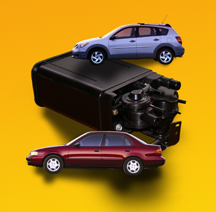
The EVAP system on the 2000-02 Chevrolet Prizm and the 2003 Pontiac
Vibe (fig. 1) performs the same tasks and
meets the same requirements as all other GM EVAP systems, but the control
principles are somewhat different. This is explained in detail in the
appropriate section of SI. As with all parts of SI, these sections are
revised on a continuing basis. And an upcoming Service Manual update
bulletin will itemize the latest revisions to SI.
Components
The Prizm/Vibe EVAP system consists of a vapor canister and three PCM-controlled
solenoid valves. (This is one solenoid more than most EVAP systems use.)
A fuel tank pressure sensor is used for diagnostics.
The vapor canister contains granules of carbon, which absorb gasoline
vapors on contact. When air is drawn through the granules, the carbon
gives up the vapors.
TIP: The canister
in this system is unique in that it consists of two halves, or chambers.
The chamber connected to the fuel tank is the vapor side of the canister,
and the chamber connected to the air cleaner is the air supply side.
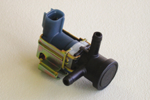
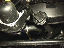
The Purge Solenoid valve is normally closed (no flow), and opens (flow)
upon command from the PCM (fig. 2). This
valve controls the application of manifold vacuum to purge the EVAP
system.
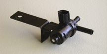
The Vent Solenoid valve is normally open (flow), and closes (no flow)
upon command from the PCM (fig. 3). This
valve allows air from the air cleaner to enter the EVAP system.
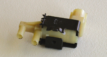
The Pressure Switching Solenoid valve, located between the two chambers
of the canister, is normally closed (no flow) (fig.
4). When necessary, it is opened (flow) by the PCM. When the
valve is open, the vapor space in the fuel tank is connected to the
canister.
Two additional valves are attached to the canister. They are operated
by spring-loaded check balls and control flow into and out of the canister.
The Evap Valve is on the vapor chamber side of the canister and the
Atmospheric Valve is on the air chamber side.
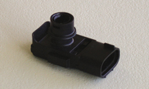
The Fuel Tank Pressure Sensor is located on the top of the fuel tank
(Vibe) or on the vapor canister (Prizm) (fig.
5).
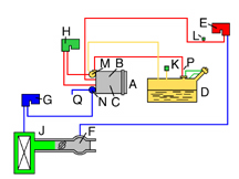
EVAP System Components (fig.
6)
A Canister
B Vapor Chamber
C Air Chamber
D Fuel Tank
E Purge Solenoid
F Manifold Vacuum
G Vent Solenoid
H Pressure Switching Solenoid
J Air Cleaner
K Fuel Tank Pressure Sensor
L EVAP Service Port
M Evap Valve
N Atmospheric Valve
P Fuel Tank Vent Valve
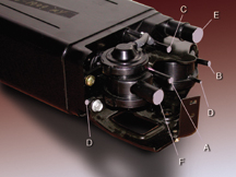
Vapor Canister Fitting Identification (fig.
7)
A From Vent Solenoid
B From Fuel Tank
C From Purge Solenoid
D To Switching Solenoid (2)
E From Fuel Tank (for refueling)
F To Drain Hose
Operation
During shutdown, the valves assume their normal, relaxed positions.
Parked Shutdown (Cooldown) -- Both the purge valve
and switching valve are closed and the vent valve is open. Under this
condition, as vapors form in the fuel tank, they are routed to the canister.
The calibration of the drain port passage check ball in the atmospheric
valve is set at 5.5 in. H2O, and above that pressure, air is allowed
to pass through the drain hose to atmosphere. On most other systems,
this air is allowed to pass through the vent solenoid to atmosphere.
Normal Operation After Ambient Air (Cold) Start --
When engine coolant temperature reaches 74° C (165° F), the
purge valve opens, applying manifold vacuum to the vapor chamber of
the canister. Because the vent valve is already open, manifold vacuum
draws air through the canister. This draws vapor into the engine to
be burned. The switching valve remains closed.
As the fuel in the tank is heated by the nearby exhaust system, fuel
evaporates and pressure within the tank increases.
TIP: This is
an important fact to understand. During normal operation of the system,
when the purge valve is turned on, and evacuation occurs, the pressure
in the fuel tank does not drop. In fact, it may even increase. This
does not indicate a problem during diagnosis.
After the vehicle reaches normal operating temperature, and other conditions
are met, the PCM runs a series of EVAP self-diagnostic tests. The purpose
of these tests is to identify whether each of the solenoid valves operates
as commanded, and also to determine if there are any leaks in the system.
Refer to the accompanying illustration as you read about the self-test
processes.
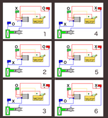
Valve Positions Indicated by X = Closed, O = Open (fig.
8)
1. Normal Operation, During Purge
2. Large Leak Test, Vacuum Increase
3. Large Leak Test, Vacuum Decay
4. Small Leak Test
5. Final Test, Vent Solenoid
6. Final Test, Pressure Switching Solenoid
1. Normal Operation, During Purge -- Before these tests
start, the vent valve is open, the switching valve is closed, and the
purge valve is open.
2. Large Leak Test, Vacuum Increase -- First, the vent
valve closes and the switching valve opens. The purge valve remains
open. This causes vacuum to increase in the entire system. Vacuum is
detected by the pressure sensor in the fuel tank. If the vacuum does
not increase, or increases beyond the specified limit, P0440, P0441,
and P0446 codes will set.
TIP: Because
more than one code will set, it’s recommended that you begin diagnosis
with the code set in Freeze Frame Failure Record.
3. Large Leak Test, Vacuum Decay -- The purge valve
is now closed, trapping vacuum in the EVAP system. Now, the pressure
sensor watches to see if, or how much, the vacuum decreases. A rapid
decrease in vacuum indicates a large leak. This will cause a code P0440
to set. This could indicate a leaky filler cap, a loose fitting, or
other large leak.
4. Small Leak Test -- If the system passes the large
leak test, the pressure sensor continues to monitor the trapped vacuum.
A slight vacuum decrease indicates a small leak. The EVAP system must
be able to identify a leak as small as 0.5 mm (0.020 inch). If a small
leak is detected, a code P0442 will set.
5. Final Test, Vent Solenoid -- Next, the system starts
to open the vent valve, admitting air into the system once again. Vacuum
should drop rapidly, indicating that the vent solenoid is working.
6. Final Test, Pressure Switching Solenoid -- Finally,
the switching valve is closed. The indicated drop in vacuum is now not
as rapid, because the pressure sensor in the tank is isolated from the
rest of the system. This indicates that the switching valve is working.
After the test is completed, the solenoid valves return to the normal
purge mode.
Once the system passes this final test, the EVAP system is declared
OK, and the necessary “PASSED” flag sets in the PCM.
If the system fails any step of the self-test, diagnostic codes will
set. SI contains the necessary steps to locate the cause(s) of the code(s).
Diagnostic Tips
IMPORTANT: Perform
the necessary diagnostic steps before replacing any components.
If you find it necessary to use the J-41413-200 EVAP Tester (the “smoke
machine”), you will need to plug the canister drain hose. Use
plug J-41413-301 for this purpose. If you do not, smoke will blow from
the opening. The check ball in the atmospheric valve is calibrated for
5.5 in. H2O, while the EVAP tester pressurizes the system to about 7-13
in. H2O.
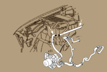
TIP: One known
place to check for leaks using the “smoke machine” was covered
in the October 2002 TechLink. This involves the corrugated plastic vapor
line between the top of the fuel tank and the vapor canister (fig.
9). It is possible that the O-ring seals used in this line are
not functioning properly, or that the vapor line is not fully connected.
Remember, when the system is purging, with the purge valve open, pressure
in the fuel tank does not drop as it does in other systems, and actually
may increase. This is normal.
The Tech 2 contains several Service Bay tests, to expedite the diagnostic
process.
The EVAP Purge/Seal Function Test allows you to simulate
the leak portion of the test.
TIP: This test
applies only to the Pontiac Vibe.
The test is performed with the engine running. At first the Tech 2 controls
all three solenoid valves to see if it is possible to apply vacuum to
the entire system, then it seals the system to see if it will hold vacuum.
This checks valve operation and also checks for leaks.
The Check Mode is most often used while driving the
vehicle to duplicate the customer concern.
TIP: This test
applies both to Prizm and Vibe.
TIP: It’s
important to capture and save any DTC or Freeze Frame information on
the Tech 2 before entering the Check Mode. All DTC and Freeze Frame
information is cleared when Check Mode is entered.
Using Check Mode temporarily makes the EVAP system much more sensitive
to problems, so diagnostics will run quicker. It also temporarily turns
all B codes into A codes, so the MIL will illuminate right away if a
condition occurs.
- Thanks to Harry Cleaver, Frank Clark and Jeff Strausser |
figure
1 |
figure
2 |
figure
3 |
figure
4 |
figure
5 |
figure
6 |
figure
7 |
figure
8 |
| |
| |
|
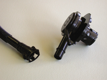
figure 9 |
| |
| return
to Table of Contents |
| |
| Service
Administrative
Messages on SI

|
http://service.gm.com
is fast becoming the one-stop-shopping place for Service
Information.
The following are now available to you in SI:
- Service manuals
- 2003 Owners Manuals
- Bulletins
- Service Administrative Messages (US)
- Campaigns
- Preliminary Information
- Service VMEs (US)
Here’s a little more detail on the latest addition, Service Administrative
Messages.
Whenever GM sends out a Service Administrative Message over GM ACCESS,
it will also be put on SI. You will no longer have to wait for the message
to be relayed to you through your dealership’s communication system.
You will have direct access to it through SI.
There are several ways to access the Service Administrative Messages.
If you know the number
-- simply use the SI Number Search feature. You must type VSS followed
by the Service Administrative Message number.
If you have already “built”
the vehicle -- select Service Manuals/Bulletins, then
use the keyword search. This will present you with a list of all documents
in SI that use the keyword, pertaining to the specified vehicle. The
Service Administrative Messages will be at the bottom of the list.
You also have another option if you have already “built”
the vehicle -- select Service Manuals/Bulletins, then select Bulletins
by Category (fig. 10), then select Service
Administrative Message (fig. 11). This
will present you a list of all Service Administrative Messages pertaining
to the specified vehicle.
Updates
The Service Administrative Messages will be updated following the standard
SI update schedule:
- update weekly on Internet
- update bi-weekly on broadcast
- update on CD whenever issued.
- Thanks to Bob Savo, Lisa Scott and Mark
Stesney |
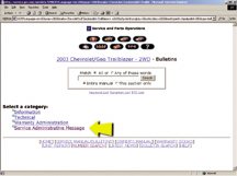
figure
10 |
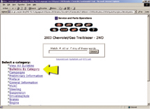
figure
11 |
| return
to Table of Contents |
|
| TechLink
Website Renovated |
During
the last month, we’ve renovated the TechLink website. You can still
find it at http://service.gm.com, fourth link.
In addition to a new look, you’ll also find some new easy-to-use
features.
First, the opening page (fig. 12) allows
you to view everything in any of four languages: Spanish, German, French,
and of course English. You can return to this page at any time to quickly
select a different language.
On most Internet service providers, you will notice that the new website
downloads much quicker than before. For you techies, it’s because
we’re using simple HTML format, so you won’t need Acrobat
Reader to view it.
Navigation is simple, and mostly intuitive. And all four languages work
exactly the same way. All the control buttons are grouped at the top of
the page. At present, several buttons are reserved for upcoming features.
You will notice that the current month’s issue of TechLink now appears
as a single, scrollable document. You can reach any article by clicking
on its title in the table of contents (fig. 13),
or simply scroll to it. Illustrations are shown in the left hand margin
and are keyed to colored references in the text. You can enlarge any illustration
simply by clicking on it.
And some good news for those who like to print articles for later reference.
Simply drag to highlight whatever you want to print, then press the print
button on your browser. Be sure to click on Selection. You can quickly
print just one article, or the whole issue.
Finally, we’ve retained the archive of every TechLink published
since January 2000. These are being presented in the format in which they
first appeared, which means that some issues will still require Acrobat
Reader..
- Thanks to Mark Stesney |
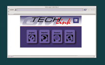
figure
12 |
figure
13 |
| return
to Table of Contents |
|
Know-How Broadcasts
for December
|
| |
 |
| Know-How
Broadcasts for December |
Emerging
Issues |
December
12 |
9:00
AM, 12:30 PM,
3:30 PM
Eastern Time |
Technology
Close-Up |
December
19 |
9:00
AM, 12:30 PM,
3:30 PM
Eastern Time |
| -
Thanks to Tracy Timmerman |
|
|
| return
to Table of Contents |
|
| Water
in AIR System |
Some
1999 - 2001 Jimmy, Blazer, and Bravada vehicles with the L35 4.3 L engine
may experience a repeat DTC P0410 with evidence of water in the AIR
pump. If there is evidence of water in the AIR pump, the pump must be
replaced.
If the pump has been previously replaced, verify that the inlet and
exhaust hoses are connected correctly before performing any additional
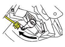
diagnosis. Figure 14 shows the correct
hose connection. Repeat failures have occurred because of these hoses
being switched.
TIP: The inlet
port on the pump is marked IN. As the hoses lie unconnected, it is very
possible to assume that the reverse hose connection is correct.
If the hoses are connected correctly or this is the first repair of
this concern on the vehicle, the source of the water could be either
from the exhaust or the inlet side of the pump. To determine if the
water originated from the exhaust side, follow the SI diagnosis for
P0410 (Document ID 554347).
TIP: When you
are at the step for testing the vacuum solenoid for proper operation,
be sure to command the pump off and verify that the vacuum goes to zero.
If not, the cause may be a stuck-open vacuum solenoid. Replace as necessary.
If you do not find an issue with the exhaust side of the system, water
may be getting into the AIR system through the inlet hose and/or the
pump itself. To prevent this, cut the existing inlet hose near the bend
and attach a 2 foot (.6 m) length of heater hose, using a coupling (fig.
15).
TIP: For 1999
and early 2000 vehicles you will need 5/8-inch (15.9 mm) heater hose
and coupling. For late 2000 and early 2001 you will need a 3/4-inch
(19 mm) heater hose and coupling.
Route the hose along the right side of the engine compartment, ending
at the evaporator core housing. Cut the hose at a 45° angle, with
the angle pointing downward. This is a dry area, and it prevents kinking
of the inlet hose, which can cause a restriction.
The exhaust check valves are also a source of water entry into the AIR
pump. This can be diagnosed by inspection of the water found in the
AIR pump. If the water has a yellow tint and has an exhaust odor, replace
both check valves. Replacement of the shut-off valve is also recommended,
due to the caustic nature of the exhaust water, which can cause failure
of the diaphragm.
To insure no water enters the pump at the pump itself, add silicone
sealer to the grommet at the wire harness leading into the pump.
-
Thanks to Marty Case and Frank Tornambe
AIR
System Operation
The secondary
air injection (AIR) system helps reduce exhaust emissions at startup
by forcing fresh, filtered air into the exhaust stream to accelerate
catalyst operation.
The vehicle control module (VCM) provides a ground for the AIR
pump relay, which energizes the AIR pump and AIR solenoid. The
AIR solenoid applies engine vacuum to the shut-off valve, allowing
it to open. With the pump running, pressurized air flows from
the pump, through the shut-off valve, through a check valve on
each bank, and into the exhaust stream.
The control module monitors the pre-catalyst HO2S, and if insufficient
flow is detected, a P0410 DTC will set. Insufficient flow may
result from water in the system, as described above. |
|
figure
14 |
figure
15 |
| return
to Table of Contents |
|
| Typical
Power Accessory Port
or Cigarette Lighter Removal |
This
procedure may be used to remove a cigarette lighter or accessory port
if the standard method in SI does not work.
To review, here’s the standard method.
Remove the power accessory port fuse. Then remove the power accessory
port socket by placing one side of the T portion of J-42059 Cigarette
Lighter Socket Remover into the tab window. Angle the other side into
the opposite tab window. Pull the power accessory port socket straight
out.
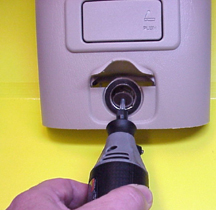
If the standard method fails to remove the socket, use the following alternate
method.
Insert a small grinding tool with a cutoff wheel into the socket (fig.
16). Remove the plastic latches in the 3 mm (0.11 in.) square windows.
With the tabs removed, use J-42059 as directed above to remove the socket.
Remove J-42059 from the power accessory port socket. Then, disconnect
the electrical connector from the power accessory port.
And finally, use your index finger to pull out the power accessory port
retainer.
- Thanks to Scott Burns |
figure
16 |
| return
to Table of Contents |
|
| Park
Brake Spring Kits |
Park
brake spring kits are available for rear disc brakes to eliminate the
need to order park brake shoe kits to service broken retainers.
88936340 for 97-2002 Classic S/T pickup and utility trucks.
88935962 for 1999-2003 2500 and 3500 C/K trucks, G vans and Hummers.
TIP: Clips will
soon be available for 1500 C/K utility and pickup trucks.
- Thanks to Dan Oden |
| return
to Table of Contents |
|
| Vibe
A/C Lack of Cooling |
On
the Pontiac Vibe, the A/C temperature control is cable operated (fig.
17). In the case of a customer concern of insufficient cooling,
check and adjust the cable. The procedure is located in SI, document 841682.
Check this adjustment before replacing the compressor.
- Thanks to Jeff Strausser |
figure
17 |
| return
to Table of Contents |
|
| |
Owners
of 1999-2002 Chevrolet Blazers, S-10 Crew Cabs, GMC Jimmys, Sonoma Crew
Cabs and 1999-2001 Oldsmobile Bravadas may comment that their vehicle
will not start after sitting for 24 hours. Customers may also comment
on a number of other symptoms:
- open cruise control fuse
- blower motor runs intermittently
- battery drain
- headlamps remain on
- headlights dim very slightly for a moment while driving at night
- endgate glass release inoperative
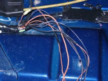
Chafed wires under the driver and passenger seats may cause these conditions
(fig. 18).These wires carry battery voltage.
If the wires are damaged, it can lead to open fuses, or circuit breakers,
and/or battery discharge. On base vehicles, passenger seat wires are located
under the carpet.
To correct these conditions, repair damaged wires and replace any fuses
or open circuit breakers.
- Thanks to Christopher Lee |
figure
18 |
| return
to Table of Contents |
|
| Door
Switch Module Service |
Use
care when replacing a door lock and side window switch module on 2003
Chevrolet and GMC full size pickup or utility.
To avoid damaging the trim panel, it’s necessary to remove a screw
that retains the switch module to the trim panel.
This is covered in SI documents 849812 and 849813.
- Thanks to Steve Arendt and Greg Mousseau |
| return
to Table of Contents |
|
| 1999-2001
Cadillac Catera Transmission Control Module (TCM) DTCs P0601 and P0602 |
When
diagnosing DTCs P0601 or P0602 set in the TCM, do not attempt to program
the TCM. The TCM is not programmable and new replacement TCMs do not
require programming. After replacing a TCM, clear all DTCs, using the
Clear Eng/Trans DTC Info function on the scan tool. After replacing
the TCM, if a DTC P0602 sets in the engine control module (ECM), clear
all DTCs using the Clear Eng/Trans DTC Info function on the scan tool.
If the DTC resets, update the ECM programming with the latest calibration
available. The service manual information database has been updated
to address this concern in SI.
- Thanks to Michael G. Van Houten |
| return
to Table of Contents |
|
| Folding
Mirror Will Not Lock in Outboard Position |
The
electrically operated folding mirrors on 2003 C/K trucks are normally
folded in or out using the mirror control switch, when the mirror selection
rocker switch is positioned at the mid-point.
You may encounter an electrically folding mirror that will not lock into
the outboard position.
These mirrors are placed in the inboard position at the assembly plant.
If the mirror is manually moved outboard, it will not lock. It must be
moved electrically.
TIP: Be sure the
pre-delivery technician is aware of this procedure. Folding the mirror
outboard manually during PDI can lead to improper mirror operation.
If this condition occurs, move the mirror back inboard manually, and then
electrically position it outboard.
Your customers can encounter the same situation if they manually move
the mirrors.
- Thanks to Tom Mannering |
| return
to Table of Contents |
|
| Vibe
Key Cutting Information |
To
duplicate a Pontiac Vibe key, use key blank p/n 88972631 and one of
the key cutters in the accompanying chart. These key cutters are available
from GM Dealer Equipment at 1.800.468.6657
- Thanks to Jeff Strausser
| Supplier |
Function |
Part
Number |
Description |
| Ilco |
Hand Operated
Code Cutting
* Accessory Kit |
74-MK1-P26
74-MK1-TO-AE-01 |
Exacta Cutter
& Case
Kit - Pontiac VIBE |
| Ilco |
Machine Duplicating
|
74-045-110VAC
|
Heavy Duty
Duplicator |
| Ilco |
Machine Duplicating
and Code Cutting |
74-029A-GM
74-029A-TOY2 |
Combo Key Duplicator
& Key Code Cutter Kit - Pontiac VIBE |
| Ilco |
Computerized
Duplicating and Code Cutting |
74-ULTRACODE
|
Ultracode Code
Cutter & Duplicator |
| Curtis |
Computerized
Duplicating and Code Cutting |
425-9100021 |
Curtis PC+ |
Available
through GM Dealer Equipment
1-800-GM-TOOLS (1-800-468-6657)
* (Numerous Exacta Kits available for all GM products) |
|
|
|
| return
to Table of Contents |
|
| REMINDER
New Vehicle Prep -- Corvette Magnetic Selective Ride Control |
Magnetic
Selective Ride Control (RPO F55) is available on 2003 Corvettes. When
the ignition is turned off, the dampers offer very little damping. So,
plastic stuffers are inserted in the dampers for shipping from the factory
(Techlink, June 2002).

The stuffers must be removed during new
vehicle prep. Failure to do so will result in customer
dissatisfaction with the vehicle’s ride quality. Refer to bulletin
02-03-11-002 for complete details.
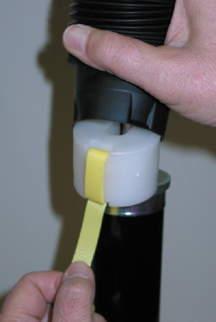
You can recognize the presence of Ride Control three ways:
- Ride Control button on console
- Corrugated dust boots on dampers
- Yellow tabs protruding from dust boots
To remove the stuffers, lift the vehicle to allow the wheels to hang
free. Reach from below, behind the tire. Compress the dust boot and
pull the yellow tab to remove the stuffer (fig.
19).
TIP: There is a stuffer on each damper, front and rear.
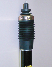
After removing the stuffer, be sure to pull the dust boot down to cover
the upper end of the damper tube (fig. 20).
- Thanks to Brad Thacher
|
figure
19 |
figure
20 |
| return
to Table of Contents |
|
| Search
Tip for Locating Product Information (PI) Documents on SI |
Since
June 17, 2002, it has been possible for you to search for PI documents
on SI. However, some people are experiencing difficulties.
Here are some tips.
After entering SI, you must click on the blue line that says click
here to enter a Vehicle Identification Number (VIN).
Next, input the vehicle’s VIN in the space provided. Be sure to
include all 17 characters. Then click on Submit.
Next, choose Service Manual/Bulletins.
When the next screen comes up, you will see a keyword search box. Do
not type anything in this box. The keyword search is not available for
PI documents. Instead, look at the list at the bottom of the screen.
Locate the line that says Preliminary
Information and click on it (fig.
21).
You will now see a list of all PI documents that pertain to the VIN
you input. You can then select any document for viewing (fig.
22).
- Thanks to GM Technical Assistance |
figure
21 |
figure
22 |
| return
to Table of Contents |
|
| 4T65E
Automatic Transmission
Pump |
When
servicing the 4T65E automatic transmission, you may encounter two parts-compatibility
issues. These involve the valve body and transmission oil pump.
Starting July 15, 2002 (Julian date 196) all 2002 and 2003 4T65E automatic
transmissions have been built with a three-piece oil pump. The service
valve body is specific to the pump design.
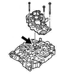
The two-piece oil pump design has the oil pump rotor support in the valve
body (fig. 23). The first-design oil pump
part number 24221299.
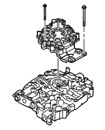
The three-piece oil pump design has the oil pump rotor support in the
oil pump (fig. 24). The second-design oil
pump part number 24225894.
Part number questions for the valve body should be directed to Partech.
2002 and 2003 4T65E automatic transmissions built before July 15, 2002
(Julian date 196) could have been built with a first- or second-design
oil pump.
The two-piece oil pump design and valve body and three-piece oil pump
design and valve body are NOT interchangeable, because the pressure regulation
and calibration are different.
- Thanks to GM Technical Assistance |
| 
figure
23
|
|
figure
24 |
| return
to Table of Contents |
|
| Bulletins
- October, 2002
This review
of service bulletins released through mid-October lists the bulletin
number, superseded bulletin number (if applicable), subject and models. |
00
– General Information
02-00-89-016; Policy Reminder on New and/or Remanufactured GM Service
Replacement Parts During Warranty Period; 2003 and Prior GM Passenger
Cars and LD Trucks, Hummer H2
01 – HVAC
02-01-39-005; HVAC System Inoperative for a Drive Cycle, Poor HVAC System
Performance in High Ambient Temperatures (Update HVAC Control Module
Software); 2002-03 Chevrolet TrailBlazer, EXT, GMC Envoy, XL, Oldsmobile
Bravada
03 – Suspension
01-03-10-010A; replaces 01-03-10-010; Inspection of Tire and Wheel Size
Prior to Diagnosis of Transmission Shifts, Poor Performance, Speedometer,
Cruise Control Concerns; 2001-02 Chevrolet, GMC Sierra with Duramax
Diesel Engine and Allison Transmission
02-03-09-002A; replaces 02-03-09-002; Intermittent Boom, Rumbling Noise
and/or Disturbance Heard in Passenger Compartment While Driving at Highway
Speeds (Replace Rear Coil Springs); 2002-03 Chevrolet TrailBlazer, GMC
Envoy with Rear Coil Springs
04 – Driveline Axle
02-04-95-001; Revised Differential Overhaul (11.5 Inch Axle) Procedure;
2001-02 Chevrolet Silverado, GMC Sierra Pickup Models
05 – Brakes
02-05-22-004A; replaces 02-05-22-004; Trailer Brakes Applied when Headlights/Park
Lamps are On, Brake Controller Illumination (Modify Brake Controller
Wiring Harness); 2002-03 Cadillac Escalade, EXT, Chevrolet Avalanche,
2001-03 Chevrolet Silverado, Suburban, Tahoe, GMC Sierra, Yukon, XL,
2003 Hummer H2
02-05-26-001; Rear Parking Brake Shoe Retaining Spring Clip Service
Kit for Drum-in-Hat (DIH) Equipped Vehicles; Specified 1998-2003 vehicles
06 – Engine/Propulsion System
01-06-04-018A; replaces 01-06-04-018; Intermittent Malfunction Indicator
Lamp (MIL) and PCM DTC P1404 (Recalibrate PCM); 2001 Buick Century,
Chevrolet Impala, Malibu, Monte Carlo, Venture, Oldsmobile Alero, Silhouette,
Pontiac Aztek, Grand Am, Grand Prix, Montana with 3.1L or 3.4L Engine
(VINs J, E -- RPOs LG8, LA1)
02-06-01-023A; replaces 02-06-01-023; Oil Leak at Oil Cooler to Engine
Block Mating Surface (Replace O-rings, Apply Sealant); 2001-03 Trucks
with 6.6L Duramax Diesel Engine (VIN 1 -- RPO LB7)
02-06-01-029; Needle Bearings Found in Oil Pan (Replace Rocker Arms);
Specified vehicles 1998-2003 with 4.8L, 5.3L, 5.7L or 6.0L V8 Engine
(VINs V, T, G, S, U -- RPOs LR4, LM7, LS1, LS6, LQ4, LQ9)
02-06-02-008; New Engine Coolant Fill Procedure; 2003 Chevrolet Express,
GMC Savana with 4.8L, 5.3L or 6.0L Gen III V8 Engine (VINs V, T, U --
RPOs LR4, LM7, LQ4)
02-06-04-046; Service Engine Soon Light On Intermittently and DTC P1441
Stored (Reprogram the PCM); 2002 Chevrolet Cavalier, Pontiac Grand Am
with 2.2L Engine (VIN 4 -- RPO LN2)
02-06-04-047; Revised Eelctronic Ignition (EI) System Diagnosis; 2002
Chevrolet TrailBlazer, GMC Envoy, Oldsmobile Bravada with 4.2L Engine
(VIN S -- RPO LL8)
02-06-04-048; Revised DTC P0540; 2001-02 Chevrolet Silverado, GMC Sierra
Pickup Models with 6.6L Engine (VIN 1 -- RPO LB7)
02-06-04-049; Revised DTC P0201 -- P0208; 2001-02 Chevrolet Silverado,
GMC Sierra Pickup Models with 6.6L Engine (VIN 1 -- RPO LB7)
07 – Transmission/Transaxle
99-07-30-016A; replaces 99-07-30-016; Diagnostic Information for Intermittent
Transmission Downshift, Slip, Busy/Cycling TCC or Noisy Cooling Fan;
2003 and Prior LD Trucks, Hummer H2 with Automatic Transmission
02-07-30-029A; replaces 02-07-30-029; New Powertrain Quality Cener for
Engine and Transmission Assembly Replacement; 2003 and Prior Passenger
Cars and LD Trucks, Hummer H3
02-07-30-032; Allison Transmission Control Module Fast Learn Procedure
Update Required After Transmission Repairs; 2002-03 Chevrolet Silverado,
GMC Sierra with Allison 1000 Series Automatic Transmission
08 – Body and Accessories
01-08-46-008A; replaces 01-08-46-008; Information on Upgrading Factory
Installed ONStar Generation 2.0 Equipped Vehicles to Generation 2.6;
Specified 2000-01 Vehicles with Factory Installed OnStar
02-08-49-007; Center Console Lid Hard to Open or Close (Lubricate Center
Console Lid Latch); 1999-2003 Chevrolet Silverado, Suburban, Tahoe,
GMC Sierra, Yukon, XL with Split Front Seats (RPO AE7)
02-08-49-008; Latch Replacement -- Instrument Panel (IP Compartment)
Procedure; 2000-03 Chevrolet Malibu
02-08-64-020; Passenger Door Outside Rearview Mirror Vibration (Install
New Reinforcement Bracket); Specified 1997-2001 MD Tilt Cab Models
09 – Restraints
02-09-40-003; Passenger Seat Shoulder Belt Too Tight or Cinches Up (Replace
Passenger Seat Belt Retractor Assembly); 2002 Chevrolet TrailBlazer,
EXT, GMC Envoy, XL, Oldsmobile Bravada
02-09-40-004; Front Seat Belt Buckles May Interfere with Door Panels
(Relocate New Buttons on Webbing); 2000-02 Chevrolet Monte Carlo
02-09-41-002; Air Bag Lamp On, Passenger Air Bag Indicator Always Reads
OFF, DTC B0092 Set (Repair Passenger Presence System PPS Sensor Harness);
2003 Cadillac Escalade, EXT, Chevrolet Avalanche, Silverado, Suburban,
Tahoe, GMC Sierra, Yukon, XL with Sensor Indicator Inflatable Restraint
Front Passenger/Child Presence Detector (RPO ALO) |
| return
to Table of Contents |
|
|
| |
|
|
|
| |
|
|
|
| |
|
|
|
|
