|
|
Note: Clicking
on any picture or illustration will open a larger version of that art.
|
|
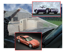
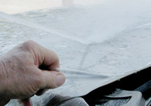
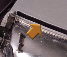
Removing
Transseal Protective Film |
Numerous
GM vehicles, including the Cadillac XLR and Chevrolet Corvette, are
delivered to the dealership with Transseal® protective film on most
horizontal surfaces (fig.1). Bulletin 03-08-51-001
has been released to provide instructions for removing this film.
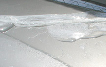
Transseal
film is installed early in the manufacturing process and protects the
vehicle surfaces during assembly as well as during shipment and storage
(fig. 2).
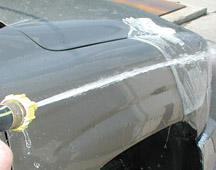
TIP: For continued
protection, leave the film on the vehicle until it’s prepped for
delivery to the customer (up to 6 months) (fig.
3).
For satisfactory removal, follow the instructions in the bulletin completely
and carefully. Here are some of the important highlights. See the bulletin
for details.
The film releases easily from the paint at an ambient temperature between
60°F and 85°F (16°C and 29°C). If the vehicle has been
parked in the sun, place it in the shade and allow the painted surfaces
to cool to this temperature. The film may tear into small pieces if
you attempt to remove it without allowing it to cool.
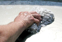
TIP: For extreme
conditions (film has been on a long time, is dirty or is difficult to
remove by hand), the bulletin suggests soaking the film with water,
then applying Murphy Oil Soap or equivalent with a woolen mitt
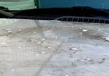
(fig. 4). Washing is particularly important when the film is
contaminated by railroad dust or other grit (fig.
5). Gritty film can flop over and contact the painted surfaces,
causing scratches.
The film must be thoroughly wetted with cool water. Never use hot water.
Use a standard tap water from a garden hose, or a pressure washer within
a range of 1000-2200 psi (6900-15000 kPa).
When wetted, the film’s appearance turns from clear to milky,
indicating that the release agents have been activated and the film
can be removed.
Perhaps the most effective method of removing the film is to peel a
corner back to break the seal (fig 6),
allow water to penetrate under the film (fig.
7), then peel with one hand while directing the water with the
other (fig. 8).
Small particles of film that remain on the surface can be removed by
applyling GM OptiKleen concentrate (do not dilute). Apply the concentrate
with a clean, soft cloth to dissolve the Transseal particles.
After the film is removed, if a haze remains on the surface, simply
wash the vehicle with soap and water to provide a polished luster.
TIP: The manufacturer
offers assistance at 1.800.307.7218 (US) or 972.286.7890 (Canada).
- Thanks to Len Tillard and George Grogan |
|
figure
1 |
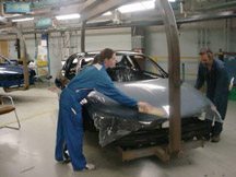
figure 2 |

figure
3 |
figure
4 |
figure
5 |
figure
6 |
figure
7 |
figure
8 |
| return
to Table of Contents |
|
|
| TechLink
Distribution |
Beginning with this issue, the quantity of TechLink
newsletters being sent to dealers is being changed. You will receive
either 3, 5 or 10 copies, depending on dealership size (US only).
Effective immediately, only dealers will receive TechLink. Internal
distribution within GM has ceased. Back issues will no longer be stocked
and cannot be ordered from the DealerWorld online store.
You are encouraged to begin using the TechLink website. This can be
located at http://service.gm.com.
In the Archives, you will find a PDF of each past issue of TechLink,
from October 1999 to the present issue. These PDFs can be used to make
additional b/w or color copies on your printer.
TIP: Each TechLink
is posted to the website the second week of the month of issue.
- Mark Stesney, publisher |
|
| |
|
|
Including Codes with Warranty Claims |
Various
module-based systems in vehicles are capable of providing a great deal
of diagnostic information in the form of diagnostic trouble codes (DTC).
You are requested to pass along as much of this information as possible.
TIP: See the May 2005 issue of TechLink for an
explanation of how to navigate the diagnostic information in SI.
Technicians -- Record the following on the repair order:
- technician observations
- customer comments
- diagnostic codes (B = body, C = chassis, P = powertrain, U = communication).
See the GM Service Policies and Procedures Manual, article 1.6.2.
Warranty Claims Administrator -- Enter the same information
in the comment section on the warranty claim for submission.
See the GM Claims Processing Manual, Section 4.2.g.
This information is continually analyzed by GM Engineering. This process
provides engineers with accurate, detailed information on a more timely
basis. The idea is to identify and resolve potential product concerns
as early as possible.
If you will provide applicable diagnostic codes, your observations,
and customer comments on every vehicle you repair, Engineering can begin
to better understand the root cause of the condition. |
|
return to Table of Contents |
|
| Top
Tier Gasoline Availability |
As
mentioned in the August 2004 TechLink, GM participated in developing
a Top Tier Detergent Gasoline standard, which exceeds the detergency
standards imposed by the EPA (applies to the United States only).
TIP: A running list of comforming gasoline brands
will appear in the Reference Guide section of the TechLink website at
http://service.gm.com.
Here’s a list of gasoline brands that meet Top Tier standards
as of August 15, 2004.
Chevron
Chevron has markets in 29 states in the West, Southwest and South.
QuikTrip
QuikTrip (not to be confused with Kwik Trip) operates convenience stores
and travel centers in:
Tulsa, OK
Springfield, MO
Kansas City, MO and Kansas City, KS
Wichita, KS
Des Moines, IA
Omaha, NE
St. Louis, MO and St. Louis, IL
Atlanta, GA
Dallas-Ft. Worth, TX
Phoenix, AZ
Bartlesville, OK
Miami, OK
Vinita, OK
Columbia, MO
-
Thanks to Jay Dankovich |
| |
| return
to Table of Contents |
|
| BCM
Setup |
IMPORTANT: This
information applies only to the 2004-05 Chevrolet Malibu and 2005 Pontiac
G6.
When you are setting up a new BCM using the Tech 2, a screen will ask
you:
Do you want to set up a new BCM?
If you answer YES, the screen will read:
Controller
is locked.
Select ENTER to continue . . .
IMPORTANT:
When you see the “Controller is locked” screen, do not assume
that this means you are unable to change options, and press EXIT. If
you do this, and then replace the BCM, this is an unnecessary replacement
of an otherwise good BCM.
You must press ENTER to continue. The screen will read:
Would you
like to Configure Options Only
Answer YES to proceed.
- Thanks to Steve Apking |
|
|
| return
to Table of Contents |
|
| Idle
Flare or Decel Stall |
This
condition may affect 2002-04 vehicles with 4 cylinder 2.2L engine
(VIN F - RPO L61) (Chevrolet Malibu, Cavalier, and Classic, Oldsmobile
Alero, Pontiac Grand Am and Sunfire).
Some owners may comment about an engine idle flare when the clutch is
depressed. Also, some owners may comment about a low speed engine decel
stall when coming to a stop.
The flare is caused by the vehicle entering stall-saver mode when the
clutch is depressed. The low speed engine decel stall is produced by
an interaction between the engine control software and the IAC motor.
Reprogram the PCM with the latest calibration available. The new calibration
was released beginning with TIS satellite data update version 6.0 for
2004 available June 2004. As always make sure your Tech 2 is updated
with the latest software version.
-
Thanks to Steve Oakley |
| |
| |
| |
|
return
to Table of Contents |
|
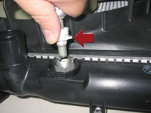
| CTS
Transmission Oil Cooler Line Fitting Service |
The following information applies to the 2003 through present Cadillac
CTS vehicles with automatic transmissions.
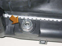
Radiators on these vehicles have two non-serviceable transmission oil
cooler (TOC) fittings that mount the in-tank cooler to the plastic radiator
end tank. These fittings are also are non-removable. A protective wall
is placed around the fitting to prevent wrench access
(fig. 9).
A threadlocking compound is used to retain the fittings to the in-tank
cooler. Any attempt to remove these fittings will damage the threads
on the in-tank cooler and damage the seal between the in-tank cooler
and the plastic radiator end tank. This can result in a coolant or transmission
oil leak and possible vehicle damage.
Proper removal of the TOC line requires the use of J-44827
(fig. 10) to properly disengage the TOC line from the fitting.
Refer to SI for the service procedure for correctly disconnecting and
re-connecting the TOC lines from the fittings (fig.
11).
-
Thanks to Chris Semanisin |
figure
9 |
figure
10 |
figure
11 |
|
return
to Table of Contents |
|
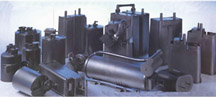
| Carbon
Canisters |
Carbon
canisters, on automobiles since 1970, have changed in external appearance
and size (fig. 12). But inside they all
perform the same function -- storing fuel vapors (hydrocarbons) that
would otherwise pollute the atmosphere. Vapors come from the fuel tank
(and the float bowl of a carburetor, if so equipped).
The outer plastic housing of the canister contains one or more chambers
of activated carbon pellets. The special properties of this material
allow the carbon canister to do its job.
Carbon Pellets
Carbon results when wood is heated to about 1,000° F without oxygen.
Volatile organic compounds in the wood are driven off, leaving behind
the carbon (charcoal) and the minerals (ash).
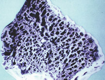
Activated carbon is treated with oxygen to open up millions of tiny
pores between the carbon atoms (fig. 13).
This material has a surface area so large that one gram may have the
surface of two to five football fields!
Activated carbon is widely used to adsorb odors or substances from liquids
or gases. The adsorbed substance is attached by chemical attraction
much like a sponge soaking up water. Fuel vapors migrate into all the
little pores in the carbon, attach themselves, and are trapped.
When the carbon adsorbs fuel vapor, an exothermic (creates heat) reaction
occurs. During a re-fueling event, the canister may have an internal
temperature of 212° F. The external temperature is closer to 150°
F, due to airflow through the canister.
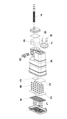
Components
The accompanying diagram (fig. 14) represents
a typical carbon canister. The activated carbon (B) is packed tightly
into the body (K) of the canister using screens (C). A spring-loaded
(L) volume compensator plate (A) continually pushes up against the screens
that hold the carbon in place.
Leaving the carbon loose would decrease effectiveness by allowing too
much air space between the particles and would allow the carbon to move
around and pulverize.
The vent to atmosphere (F) is controlled by a solenoid (D) that is normally
open. In this diagram, the vent solenoid is integral with the canister.
A replaceable filter (E) keeps dust from intruding into the canister
and reducing its effectiveness. The liquid trap (J) consists of a cover
and a series of molded ramps that prevent liquid fuel from entering
the canister from the fuel tank vapor tube (H). Finally, vapor is drawn
from the canister by engine vacuum through the vapor purge tube (G).
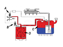
Evaporative Emission System
The carbon canister is part of the Evaporative Emissions System.
In the vapor storage mode (fig.
15), fuel vapors from the fuel tank travel through plumbing to
the canister. The amount of vapor created depends on:
- ambient air temperature
- Reid Vapor Pressure of fuel
- heat from road surface and exhaust system
- heated return fuel
During this mode, the Canister Purge Solenoid (A) is closed (unenergized)
and the Vent Solenoid (B) of the canister is open (unenergized) to the
atmosphere. Fuel vapor (C) is adsorbed by the activated carbon in the
canister (D). Any air displaced from the canister by the vapor is pushed
out the vent. Fuel vapors will not “leak” out of the vent
to any great extent due to the attraction of the vapor to the carbon.
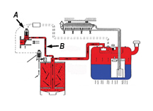
During operation of the vehicle, the control module (PCM, VCM, etc.)
commands a purge mode (fig. 16),
in which the Purge Solenoid (A) is pulse-width-modulated, similar to
a fuel injector. The vapors are pulled by engine vacuum (B) out of the
carbon and fuel tank into the intake manifold. This resembles squeezing
water out of a sponge for re-use. The vapors are removed from the carbon’s
tiny pores, preparing it for more storage.
Things That Can Go Wrong With a Carbon Canister
Vapor system-related codes to know:
P0440 |
Evap
Emission (EVAP) System |
P0442 |
Small
leak detected |
P0446 |
System
performance |
P0455 |
Large
leak detected |
P0496 |
Flow
during non-purge |
P1441 |
Flow
during non-purge |
TIP:
Some code numbers have changed recently. P0440 became P0455. And P1441
became P0496.
Carbon canister loose in brackets – The canister bouncing
around breaks up the carbon and turns it into dust that can at times
be found in the purge solenoid. This may not set a code unless enough
carbon dust restricts the flow in the Evap system, or prevents the purge
solenoid from operating properly.
Damage incurred by foreign objects striking the canister and breaking
the canister body – This will cause major leakage during
evap testing, possibly causing a P0442 or P0455 and of course venting
vapors to the atmosphere.
Water in the canister – Water can be pulled in through
the vent solenoid if the solenoid or its vent tube are exposed to water
(such as the bed drain on a C/K pickup, Bulletin 00-06-04-024). Water
inhibits the carbon’s ability to adsorb vapor. Water tends to
stay in the carbon for a period of time even with purging. This has
a high potential of setting a P0446.
Fuel saturation – Overfilling of the fuel tank forces
fuel into the canister. Liquid fuel inhibits the carbon’s ability
to adsorb and may cause a restriction in the system, causing a P0446.
Dust and dirt contamination – Almost always pulled in
through the vent solenoid. Initially this causes a flow problem and
eventually inhibits the carbon’s ability to adsorb. A filter is
usually used in the vent path of the carbon canister to trap contamination
before it gets to the canister. The filter may be located in the canister
under a cover or remotely mounted at the end of the vent (air) tube.
It’s always located before the vent solenoid. Check SI for the
location of the filter. When a P0446 code is set, this filter and the
entire vent path should be checked for restrictions.
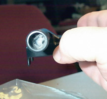
Insect infestation – Due to the heat generated during
adsorption, the canister becomes attractive to insects (fig.
17). Generally they nest in the vent tube of the vent solenoid
and can cause a restriction resulting in a P0446. Always check the entire
length of vent tubing for foreign material if a code P0446 is set, and
clean as necessary.
- Thanks to Randy Pearl and Paul Reed |
figure
12 |
figure
13 |
figure
14 |
figure
15 |
figure
16 |
figure
17 |
| |
| |
| |
| return
to Table of Contents |
|
| Cab
Rattle Noise |
Owners
of some 2001-05 Chevrolet Silverados and GMC Sierras may comment of
a rattle type noise coming from the rear of the cab during body twist
maneuvers or over bumps. This noise may be coming from the dealer-installed
GM Tubular Assist Bars (Nerf Bars). Several cases have been reported
were the gasket between the Tubular Assist Bar and the body mounting
bracket were distorted and the Assist Bar had cut through the gasket,
making metal-to-metal contact with the body bracket. The gasket can
be distorted or cut by over-tightening the body bolts during installation
of the Assist Bars.
To correct this concern, replace the Assist Bar gaskets, which are included
in hardware kit 88961680 (brackets, bolts, and washers). Be careful
when installing the body bolts. Apply blue Loctite and tighten the bolts
to 91 Nm (65 lbs. ft.).
DO NOT use an air impact wrench.
- Thanks to Tom Clapham |
|
| return
to Table of Contents |
|
| Instrument
Panel Itch or Ticking Noise |
Owners of some LeSabres may encounter a creak or tick noise in the instrument
cluster area while driving over bumps. This noise is due to the mispositioned
felt strip on the top pad between the I/P and the cluster. The felt
strip is usually too far forward, toward the windshield.
To correct this condition, reposition the felt strip toward the driver
(fig. 18).
- Thanks to Bill Metoyer |
figure
18 |
|
return
to Table of Contents |
|
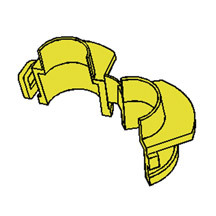
| Cobalt
Door Upper Front Trim Panel |
On the 2005 Cobalt, the method for attaching the Side Door Upper Front
Trim Panel (“shark fin”) depends on the trim level.
On base models with manual outside rearview mirror, the extension is
removable by pulling the trim piece straight back from the door; it
is held in place by clips (fig. 19).
On uplevel models with power outside rearview mirror, the extension
is heat-staked to the door trim panel. There is no provision for removal.
Attempting to do so will result in damage to the door trim panel.
-
Thanks to Ed Kay |
|

figure
19 |
|
return
to Table of Contents |
|
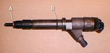
| Duramax
Diesel Injector Tips |
Attention
to detail is important when working with Duramax diesel injectors. Perform
a visual inspection of the fuel line connections and the area around
the injector for corrosion and contamination before removal.
Follow the removal and installation procedures in SI, ensuring that
all areas are clean and free of dirt and contaminants before installing.
Before installing the injector, move aside any wires or other obstacles
that may interfere with installation.
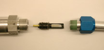
Be sure the high-pressure copper seal (A) is attached to the bottom
of the injector (fig. 20). If the seal
is damaged, it could cause a compression leak, leading to a running
condition and high imbalance rates.
Be sure the rubber O-ring (B) is seated in the mid-barrel groove on
the injector. The rubber O-ring prevents water and contaminants from
getting between the injector and the engine.
Be sure the injector and hold-down bracket are seated and in the proper
position, and the attaching bolt is torqued to the appropriate specification.
- Thanks to Art Seymour |
| |
figure
20 |
|
return
to Table of Contents |
|
| Inline
A/C Filter |
Service
Technicians Voice Concerns – GM Listens and Delivers
It’s common A/C service knowledge that, when a compressor fails,
contaminants are carried throughout the system. Thorough refrigerant
flushing is time-consuming and does not assure complete 100% removal.
Although some thermal expansion valves (TXVs) have their own screens,
they don’t have the surface area to contain compressor failure
debris. So, for years, a service in-line filter has been recommended
to prevent TXV plugging.
The original GM service filter (fig. 21)
effectively contained contaminant material. But, this part had several
installation shortcomings that technicians readily pointed out. These
included:
- Installation leak sensitivity -- any deviation from approved procedure
could result in
leaks.
- Installation labor -- required double installation to ensure no leaks.
- Capacity limitation -- certain compressors and systems would benefit
from additional contaminant capacity.
- Numerous models -- the parts department never seemed to have the right
unit in stock.
Realizing these shortcomings existed, GM worked with the original supplier
to redesign the filter to address all of the technicians’ concerns.
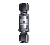
The resulting filter
(fig. 22) provides a larger capacity, universal
application, and enhanced reliability in the real-world field environment.
In late 2003, ACDelco released the redesigned filter 15-10413 (GM p/n
89016656).
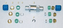
A Nut
B Ferrule
C Seal
D Tube Adaptor
E Filter Body
F Orifice Retainer Clip
What’s different about this new service filter?
Provides a simplified, robust, leak-free installation.
The original filter design incorporated an O-ring to seal around the
A/C tube OD. Successful installation required a smooth round surface.
Technicians pointed out the obvious field reality:
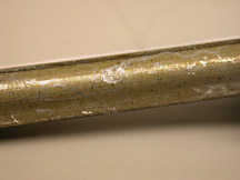
- Tubes are not all perfectly round (fig. 23)
- Tube finish has surface imperfections (fig.
24)
- Installing the filter collar twice to assure proper seating is inefficient
and time-consuming.
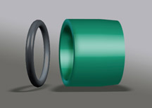
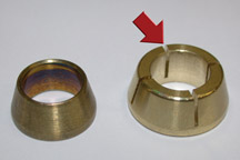
The redesigned filter replaces the single O-ring with a robust tapered
sealing sleeve (fig. 25). The seal provides
10 times the sealing area and greatly increases the seal’s ability
to overcome tube irregularities. The addition of slots (fig.
26) on the brass ferrule permits the ferrule to seat correctly
on the first installation and increases compression on the seal.
Increased debris containment
The redesigned filter incorporates a new screen within a new body. This
not only shortens the overall filter length but also increases the capacity
three-fold, while reducing restrictions to pressure and flow.
Universal application and ability to cover new systems
The old filter had four part numbers to accommodate two tube sizes,
with a variation of each to incorporate an 0.072-inch orifice. The new
unit is universal and fits the 5/16-inch, 3/8-inch and 1/2-inch tube
sizes common to TXV systems.
In addition, the universal unit permits reworking an existing orifice
(regardless of size -- 0.072-inch, 0.062-inch, 0.052-inch, etc.) and
incorporating it into the filter (fig. 27).
This greatly simplifies inventory and increases flexibility.
TIP: Because
of the interchangeable fittings, the filter can be used to join different
tubing sizes. It can also be used as a splice to repair a damaged tube
or to replace a damaged thread.
Overall, the new filter provides the insurance technician have been
requesting to reduce comebacks on compressor replacements -- especially
on vehicles with rear A/C systems.
- Thanks to Jim Resutek |
|
figure
21 |
figure
22 |

figure
23 |
figure
24 |
figure
25 |
figure
26 |
figure
27 |
| return
to Table of Contents |
|
| Technical
Assistance Information |
This
information applies to US dealers only and is effective as of September
13, 2004.
GM Technical Assistance Center (GMTAC) would like to be able to resolve
your concern during the first phone call. Bulletin 01-00-89-011B explains
the procedures that are now in place to help this happen.
The bulletin contains a copy of the GM TAC form, which you are required
to fill out before placing a TAC phone call. In filling out the form,
you are required to obtain specified information. A few of them are
emphasized here. See the bulletin and the form for complete details.
1. You are required to follow Strategy Based Diagnostics and include
your findings on the form.
2. You are required to provide the SI document number of the technical
issue you’re working on.
3. You are required to have the dealer code, VIN, and RO number.
Having these steps completed before you call will allow the consultant
to spend time researching the issue rather than giving out service information
that’s already available at your dealership.
TIP: When you
call TAC, a recorded message will remind you of these requirements before
you’re connected to a consultant.
TIP: SI is now
being updated every 24 hours, so the latest PI and bulletin information
is available at your dealership. And remember, a VIN is no longer required
to access PI information on SI.
The GM TAC form also contains space for you to close the TAC case when
it has been resolved. This information is important in helping TAC update
the database with the latest information, which will be useful to help
future callers with the same condition.
And finally, there’s a space for you to provide feedback on the
survey portion fo the form, regarding the assistance you received. TAC
will use this information to make continuous quality improvements.
- Thanks to Sean Garrison |
|
| return
to Table of Contents |
|
| M74
Allison LCT1000 PTO Gear Applications |
Some
2004-05 Chevrolet and GMC pickup trucks equipped with Allison LCT1000
transmissions do not have PTO (power take-off) gears installed on the
rotating housing. Instead, they have a tone ring for the turbine speed
sensor that is not able to drive a PTO.
2001-04 |
6.6
LB7 (VIN code 1) |
PTO
gear |
2001-05 |
8.1
L18 (VIN code G) |
PTO
gear |
2004-05 |
6.6
LLY (VIN code 2) pickup |
no
PTO gear |
2004-05 |
6.6
LLY (VIN code 2) chassis cab |
PTO
gear |
If a customer desires
to use a PTO on a pickup truck equipped with a LLY 6.6 engine, it will
be necessary to install a rotating housing that has a PTO gear installed
on it, p/n 29540518.
TIP: This procedure
is not covered under warranty and is at the customer's expense.
-
Thanks to Rusty A. Sampsel |
| return
to Table of Contents |
|
| Changes
To Personalization And Memory Recall |
Starting
in 2005, the mid-size Chevrolet, GMC and Buick SUVs will have a change
in personalization operation. The key fob will no longer recall seat position,
mirror position, radio presets, HVAC settings and/or DIC personalization
settings for each driver.
Vehicles equipped with memory seats RPO AAB will recall seat and mirror
positions only for driver 1 and 2. To activate the memory recall feature,
each driver will need to program the seat and mirror settings to one of
the memory positions.
The driver must select driver 1 or 2 when entering the vehicle so the
seats and mirrors can recall to the programmed position. No other personalization
features will follow the driver 1 or 2 button.
Also, the DIC will no longer display driver 1 or 2. This is a engineering
change and no repairs should be attempted.
- Thanks to Dino Poulos |
|
|
|
return
to Table of Contents |
|
| Steering
Will Not Lock |
Owners
of some 2004-05 Chevrolet Colorado and GMC Canyon vehicles may comment
that the steering will not lock when the key is removed from the ignition.
This is a normal condition. The Colorado and Canyon never had this feature.
The owner’s manual and service information were published incorrectly.
They are both currently in review and will be updated with the correct
information. Do not perform any repairs for this concern.
-
Thanks to Dino Poulos |
|
|
| return
to Table of Contents |
|
| Seatbelt
Retractor |
Owners
of some 2004 Chevrolet Corvettes may state that the driver or passenger
seatbelt will not extend from the seatbelt retractor.
If a resolution can't be found through normal diagnosis, replace the
affected seatbelt and install a new bolt (p/n 15017724) and new washer
(p/n10257765) and discard the original bolt and washer. The larger diameter
washer distributes the clamping load evenly on the lower seatbelt retractor.
-
Thanks to Paul Radzwilowicz |
| return
to Table of Contents |
|
| Tire
Scrub Noise On Low Speed Turns |
Owners
of some 1999-2005 Full Size Trucks and Utilities may experience tire
scrub noise on low speed turns (parking lot maneuvers). The steering
rod (centerlink) can be installed backwards on all trucks and utilities
with recirculating ball type steering that do not use a steering dampener.
To determine the correct installation of the steering rod, compare to
a like vehicle. In a correct installation, the steering rod should curve
to the rear, outboard of idler/pitman attachment holes and inboard of
the inner tie rods.
The idler and pitman attaching holes are tapered in only one direction.
With the steering rod installed incorrectly, the curved portion of the
rod between the idler/pitman holes and inner tie rods curves toward
the front of the vehicle. Remove and correctly reinstall the steering
rod (centerlink).
-
Thanks to Jim Will |
|
|
| return
to Table of Contents |
|
| Windshield
Upper Reveal Molding |
Some
2003-05 HUMMER H2s may have a less than perfect fit of the windshield
upper reveal molding which may contribute to wind noise in the windshield
area.
To replace the molding, you no longer have to order and replace a complete
windshield assembly. The molding, p/n 15060528, is now available through
Service Parts Operations. The labor operation is B7540 and pays straight
time. Refer to SI document number 800535 for replacement procedures.
-
Thanks to Paul Radzwilowicz |
|
|
| return
to Table of Contents |
|
 Car Issues
– Fix It Right The First Time (new issues in bold) Car Issues
– Fix It Right The First Time (new issues in bold) |
Model
Year(s) |
Vehicle
Line(s) --
Condition |
Do
This |
Don’t
Do This |
Reference
Information / Bulletin |
1997-2005 |
Buick
Century, Regal – Broken
Armrest Lid Latch |
Replace
lid latch only. |
Don’t
replace console armrest lid (Regal) or front seat center storage
armrest (Century) when only latch is needed. |
03-08-49-018A |
2004-2005 |
Grand
Prix – Outside Rearview Mirrors |
Replace
mirror glass
or motor. |
Don’t
replace complete mirror assembly. |
04-08-64-009 |
2004 |
Grand
Prix – Steering, Suspension or Cradle Click Noise |
Re-torque
right steering gear mount. |
Don’t
replace steering gear or cradle. |
03-02-32-048 |
2000-2003 |
Century,
Regal, Lumina, Impala, Monte Carlo, Grand Prix, Intrigue with
3.8L L36 Engine – Coolant Leak |
Replace
upper intake manifold gasket only. |
Don’t
replace upper intake manifold assembly for coolant leak condition. |
03-06-01-016 |
2001-2004 |
Aztek,
Rendezvous (FWD), Venture/Montana/Silhouette – Pop and/or
Rattle in Exhaust Down Pipe |
Follow
procedure in bulletin using clamp p/n on down pipe to correct
rattle/buzz noise. |
Don’t
replace converter assembly for rattle/buzz noise without completing
instructions in bulletin. |
03-06-05-003 |
2000-2004 |
All
Cars with 4T40/4T45E and 4T65E – Light On/Various Transmission
Codes Stores |
Check
transmission 20-way connector for secure connection (disconnect
and reconnect). |
Don’t
replace transmission, TCC PWM, VSS, PCS or valve body. |
02-07-30-022B |
1998-2004 |
Seville
– Heated Seat Inoperative |
Replace
only needed heating element. |
Don’t
replace entire seat cover if heated seat element is inoperative. |
01-08-50-002C |
2000-2004 |
Cavalier/Sunfire/Alero/Grand
Am – Inoperative Sunroof Module |
Retime
module or replace only motor for inoperative complaints. |
Don’t
replace entire sunroof module assembly. |
03-08-67-009A |
2003-2004 |
Cavalier/Sunfire
– Air Conditioning Compressor Noisy |
Inspect
for ground out conditions that can cause A/C compressor noise
complaints. |
Don’t
replace A/C compressor for excessive noise complaint without inspecting
for ground outs. |
03-01-38-012 |
1999-2004 |
All
Cars and Trucks – Brake Warranty, Service and Procedures |
Issue
One: Refinish
brake rotor.
Issue Two: Measure
for LRO.
|
Issue One: Don’t replace brake rotors.
Issue Two: Don’t measure for LRO.
|
00-05-22-002D |
|
| return
to Table of Contents |
|
|
 Truck
Issues – Fix It Right The First Time Truck
Issues – Fix It Right The First Time
|
Model
Year(s) |
Vehicle
Line(s) --
Condition |
Do
This |
Don’t
Do This |
Reference
Information / Bulletin |
2001-2003 |
Fullsize Pickups – Injector Replacement for High Flow Rates |
Use
Bulletin 04-06-04-007A for injectors with high fuel return rates.
Use Special Policy 04039 for 01-02 vehicles. |
Don’t
replace 8 injectors except for high fuel return rates. Other injector
failures are fix as failed. |
Special
Policy
04039 |
2004-2005 |
All Cars and Trucks – State-of-Charge Upon Delivery of New
Vehicle |
Check
the battery’s state-of-charge per revised PDI procedure. |
Don’t
remove and replace the battery. |
02-06-03-009A |
2003-
2005 |
Avalanche, Suburban, Tahoe, Silverado, Yukon/XL, Sierra, Escalade
– Snap/Popping Noise from
Front of Vehicle |
Slot
left side mounting holes on front crossmember
per bulletin. |
Don’t
replace crossmember. |
03-08-61-002B |
2002-2004 |
Fullsize
and Midsize Pickups and Utilities – Labor Operation Assignments
for Control Module Reprogramming |
When
submitting claims for reprogramming an electronic module, use
correct labor operation that reflects module being programmed. |
Do
not use K5364, which is for reprogramming transmission control
module (TCM), when reprogramming TCCM. |
02-04-21-006D
02-06-04-057D |
2002-2004 |
Fullsize and Midsize Pickups and Utilities – Sleepy New
Venture Gear Transfer Case Control Module |
Verify
sleepy module as primary cause, per bulletin. Reprogram TCCM with
latest software released 3/11/04. |
Don’t
replace encoder motor or transfer case. Replace module only if
C0550 DTC shows as current or in history. |
02-04-21-006D |
2002-2003 |
Chevrolet
Avalanche and Cadillac Escalade EXT – Cargo Covers and Cladding
Faded or Stained |
Thoroughly
clean, dry and treat the components with “Armor-dillo.” |
Don’t
replace cargo covers for this condition. |
04-08-111-001A
(July
2004)
|
| 2002-2004 |
All
Passenger Cars and Trucks – Air Conditioner Compressor Diagnosis |
Follow
SI and bulletin for diagnostic information before compressor replacement. |
Don’t
replace air conditioning compressor. |
01-01-38-013A
03-01-38-019
|
| 2002-2004
(models with HomeLink™ option) |
All
TrailBlazers, All Envoys, Bravada, Rainier with HomeLink Universal
Transmitter – Programming Diagnosis |
Use
J 41540 – GM Integrated HomeLink Tester. Follow SI and refer
customers to
Owner’s Manual. |
Don’t
replace the HomeLink Transceiver without validating internal fault
recognized by J 41540. |
01-08-97-001B |
| 2002-2004 |
All
TrailBlazers, Envoy, Envoy XL, Bravada – Squeak/Rub/Scrub
Type Noise in Steering Column |
Lubricate
and remove material, per bulletin. |
Don’t
replace the
upper or lower
intermediate shaft. |
02-02-35-006A
|
2001-2004 |
Fullsize
Pickups and Utilities – Servicing Wide Load Mirrors (RPO
DPF) |
Replace
individual
parts as needed. |
Don’t
replace the complete mirror assembly. |
03-08-64-028
|
|
| return
to Table of Contents |
|
|
| Know-How
Broadcasts for November |
| |
 |
| Know-How
Broadcasts for November |
| November
11, 2004 |
10280.11D
Emerging Issues |
|
| November
18, 2004 |
10280.23D
To Be Announced |
9:00
AM, 12:30 PM,
3:00 PM Eastern Time |
| -
Thanks to Tracy Timmerman |
|
|
| return
to Table of Contents |
|
|
